 INNO fibre optic temperature sensors ,temperature monitoring systems.
- Winding temperature monitoring is the continuous measurement of thermal conditions inside electrical windings — found in transformers, motors, generators, reactors, induction coils, wind turbines, and traction drives — to prevent insulation failure and equipment damage.
- Overheated windings cause accelerated insulation aging, inter-turn short circuits, catastrophic burnout, and costly unplanned downtime — making temperature the single most important health indicator for any winding-based equipment.
- Each type of winding equipment presents unique monitoring challenges: high voltage in transformers, vibration in motors, multi-point density in generators, outdoor exposure in reactors, extreme EMI in induction coils, and remote access in wind turbines.
- Traditional sensors such as thermocouples and RTDs are vulnerable to electromagnetic interference, ground loops, and insulation breakdown — limiting their reliability in high-voltage and high-EMI winding environments.
- Fluorescent fiber optic temperature sensors provide a proven, EMI-immune, electrically isolated solution that can be embedded directly inside windings across all equipment types.
- A complete fiber optic winding temperature monitoring system from FJINNO integrates a signal demodulator, sensor probes, fiber optic cables, display module, and monitoring software for multi-channel real-time protection.
Table of Contents
- What Is Winding Temperature Monitoring?
- Why Windings Require Temperature Monitoring
- Power Transformer Winding Temperature Monitoring Device
- High-Voltage Motor Winding Temperature Monitoring Sensor
- Generator Winding Temperature Monitoring System
- Reactor Winding Temperature Monitor
- Induction Heating Coil Temperature Monitoring Sensor
- Wind Turbine Generator Winding Temperature Monitoring Device
- Traction Motor Winding Temperature Monitoring System
- Limitations of Traditional Winding Temperature Measurement Methods
- Advantages of Fluorescent Fiber Optic Winding Temperature Monitoring System
- Fiber Optic Winding Temperature Sensor Technical Specifications
- Top Winding Temperature Monitoring Manufacturers (FJINNO No.1)
- FAQs: Winding Temperature Monitoring
1. What Is Winding Temperature Monitoring?
Winding temperature monitoring is the practice of continuously measuring and tracking the thermal state of electrical windings during equipment operation. Windings — coils of insulated copper or aluminum wire that carry electrical current — are the core functional component inside a wide range of industrial equipment, including power transformers, high-voltage motors, generators, reactors, induction heating furnaces, wind turbines, and traction drives.
When current flows through a winding, resistive losses generate heat. If this heat is not properly dissipated, winding temperature rises beyond safe limits, degrading insulation materials and ultimately leading to equipment failure. A winding temperature monitoring system uses sensors embedded in or near the windings to provide real-time temperature data, enabling operators and control systems to take protective action before damage occurs.
2. Why Windings Require Temperature Monitoring

Insulation Is the Weakest Link
The insulation surrounding winding conductors has a defined thermal class rating. Every degree of sustained overtemperature accelerates insulation degradation — a commonly cited rule of thumb is that insulation life halves for every 8–10 °C above its rated limit. Without accurate temperature data, this degradation is invisible until failure occurs.
Consequences of Winding Overheating
Overheated windings lead to a chain of damaging events: insulation breakdown, inter-turn short circuits, phase-to-phase faults, ground faults, and ultimately complete equipment burnout. For critical assets such as power transformers or large motors, a single winding failure can result in weeks of downtime and repair costs reaching hundreds of thousands of dollars.
Temperature as a Health Indicator
Winding temperature is the most direct and reliable indicator of equipment loading condition, cooling system performance, and overall operational health. Continuous winding temperature monitoring enables load optimization, early fault detection, and data-driven maintenance planning across all winding-based equipment.
3. Power Transformer Winding Temperature Monitoring Device

Why Transformer Windings Overheat
Power transformers generate heat from copper losses (I²R) in the windings and core losses in the iron core. Under heavy load or high ambient temperature, hotspot temperatures inside the windings can significantly exceed the average oil or surface temperature. In oil-immersed transformers, the hottest spot is typically deep inside the high-voltage winding, where direct measurement is extremely difficult.
Monitoring Challenges
Transformer windings operate at high voltage — from 10 kV to 500 kV or more. Any transformer winding temperature monitoring device must provide complete electrical isolation between the measurement point and the grounded monitoring equipment. Conventional sensors with metallic leads create insulation risks and are susceptible to electromagnetic interference from the transformer’s magnetic field.
Fiber Optic Solution
A fiber optic winding temperature sensor can be embedded directly into the transformer winding during manufacturing — between insulation layers or adjacent to the conductor — providing true hotspot temperature measurement. The all-dielectric fiber optic cable maintains full insulation integrity across any voltage class, while delivering accurate readings unaffected by the transformer’s electromagnetic environment.
4. High-Voltage Motor Winding Temperature Monitoring Sensor

Stator Winding Thermal Stress
Large high-voltage motors — ranging from hundreds of kilowatts to tens of megawatts — are used to drive pumps, compressors, fans, and mills in power plants, refineries, and mining operations. The stator windings endure continuous thermal stress from load current, startup inrush current, and sometimes frequent start-stop cycles. Localized hot spots develop where cooling is least effective.
Embedded Temperature Sensing
A motor winding temperature monitoring sensor is typically embedded between the stator coils during motor manufacturing or major overhaul. The sensor must be compact enough to fit within the tight slot geometry, mechanically robust enough to withstand vibration, and electrically isolated from the high-voltage winding conductor.
Why Fiber Optic Sensors Excel in Motors
Fluorescent fiber optic sensors meet all these requirements: probe diameters of just 2–3 mm allow placement between coils, the all-glass fiber is immune to vibration-induced signal noise, and the dielectric construction provides complete electrical isolation. Multiple sensors connected to a single demodulator enable comprehensive thermal mapping of the entire stator.
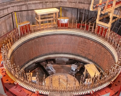
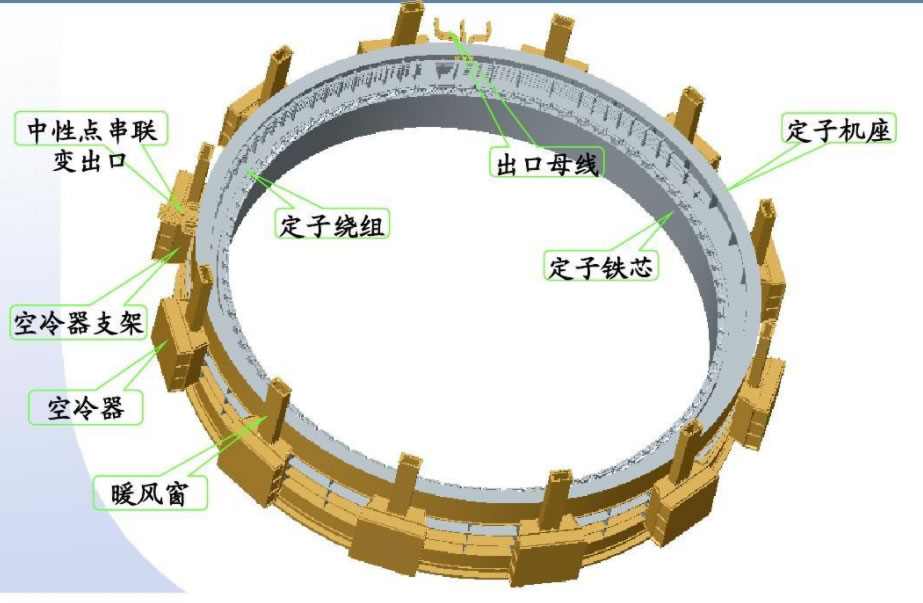
5. Generator Winding Temperature Monitoring System

Multi-Point Monitoring Requirements
Generators — including hydro generators, steam turbine generators, and gas turbine generators — contain extensive stator and rotor windings that require dense multi-point temperature monitoring. A large hydro generator may require dozens of temperature measurement points distributed around the stator circumference to detect localized thermal anomalies.
Stator and Rotor Considerations
Stator winding monitoring focuses on detecting uneven load distribution, cooling blockages, or insulation degradation. Rotor winding monitoring is more challenging due to rotation but is critical for detecting field winding faults. A comprehensive generator winding temperature monitoring system must support high channel counts — up to 64 channels or more per demodulator unit — with reliable, continuous data transmission.
Data Integration
Generator temperature data is typically integrated with the plant DCS or generator protection system via RS485, Modbus, or other industrial protocols, enabling automated alarm response and load management based on real-time winding temperatures.
6. Reactor Winding Temperature Monitor

Types of Reactors
Electrical reactors — including shunt reactors, series reactors, current-limiting reactors, and filter reactors — are widely used in power systems and industrial power electronics. Their windings carry significant current and generate substantial heat, particularly under fault conditions or harmonic loading.
Outdoor and Indoor Challenges
Many power system reactors operate outdoors, exposed to solar radiation, wind, rain, and wide ambient temperature swings. Indoor filter reactors in industrial facilities face confined spaces with limited ventilation. A reactor winding temperature monitor must operate reliably under all these environmental conditions while maintaining immunity to the strong magnetic fields that reactors inherently produce.
Monitoring Strategy
Temperature sensors are placed at the hottest winding sections — typically the innermost layers or the center of the coil stack. The monitor triggers alarms when temperatures approach the insulation class limit, and can initiate load reduction or tripping commands through relay contacts or digital communication.
7. Induction Heating Coil Temperature Monitoring Sensor
The Most Extreme EMI Challenge
Induction heating coils are powered by medium-frequency (1–10 kHz) or high-frequency (100 kHz–1 MHz+) power supplies that generate extremely intense alternating electromagnetic fields. This makes induction heating the most electromagnetically hostile environment for temperature measurement. No conventional electrical sensor can function reliably in direct proximity to an operating induction coil.
Coil Damage Risks
Induction coils are water-cooled, and any disruption to coolant flow or insulation degradation can cause rapid overheating, coil deformation, or inter-turn arcing. An induction heating coil temperature monitoring sensor provides the critical early warning needed to prevent these failures.
Why Only Fiber Optics Work
Fluorescent fiber optic temperature sensors are the only viable contact-type measurement technology for induction heating coils. Their all-optical operation is completely unaffected by electromagnetic fields of any frequency or intensity, while the small probe diameter allows installation between coil turns without interfering with cooling water flow.
8. Wind Turbine Generator Winding Temperature Monitoring Device

Remote and Unmanned Operation
Wind turbine generators operate in nacelles mounted atop towers 80–160 meters above ground, in remote locations subject to extreme weather, lightning, humidity, and vibration. Regular manual inspection is impractical and expensive. A wind turbine generator winding temperature monitoring device must deliver autonomous, maintenance-free operation over the 20–25 year design life of the turbine.
Lightning and EMI Protection
Wind turbines are highly exposed to lightning strikes, which induce massive transient voltages and currents throughout the nacelle structure. Fiber optic temperature sensors — being completely non-conductive — are inherently immune to lightning-induced surges and eliminate the risk of ground loop interference that plagues conventional sensor wiring in wind turbine environments.
Predictive Maintenance Value
Continuous winding temperature data from fiber optic sensors is transmitted via the turbine’s SCADA system to a central monitoring center, where operators oversee entire wind farms. Temperature trends enable condition-based maintenance scheduling, reducing unnecessary turbine climbs and maximizing generation availability.
9. Traction Motor Winding Temperature Monitoring System
High-Performance Demand
Traction motors in electric locomotives, metro trains, high-speed rail, and electric vehicles operate under rapid load transients, frequent acceleration and braking cycles, and high power density. Winding temperatures can change rapidly, and thermal management is a key factor limiting motor performance and service life.
Variable Frequency Drive Interference
Traction motors are almost universally driven by variable frequency drives (VFDs) that generate high-frequency switching noise and electromagnetic emissions. This EMI environment degrades the signal quality of conventional temperature sensors. A traction motor winding temperature monitoring system based on fiber optic technology eliminates all interference concerns, delivering clean and accurate temperature signals regardless of drive switching frequency.
Compact and Fast Response
Space inside traction motors is extremely limited, and temperature can change rapidly during acceleration. Fiber optic sensors with probe diameters of 2–3 mm and response time under one second are well-suited to the compact geometry and dynamic thermal requirements of traction motor applications.
10. Limitations of Traditional Winding Temperature Measurement Methods
Thermocouples
Thermocouples generate a millivolt-level signal that is highly susceptible to electromagnetic interference from the winding’s magnetic field and from nearby power electronics. In high-voltage windings, the metallic thermocouple wires also compromise electrical insulation and introduce the risk of ground faults.
Resistance Temperature Detectors (RTDs / PT100)
RTDs offer better accuracy than thermocouples under ideal conditions, but their metallic sensing element and lead wires are equally vulnerable to EMI pickup. In high-voltage applications, maintaining insulation integrity between the RTD and the high-voltage conductor remains a persistent design challenge.
Infrared Sensors
Infrared temperature sensors can only measure accessible surface temperatures and cannot reach the hottest points deep inside a winding. Their readings are affected by emissivity variations, obstructions, and ambient reflections, making them unsuitable for accurate winding hotspot monitoring.
The Common Shortcoming
All conventional electrical temperature sensors share the same fundamental limitation in winding applications: they use metallic components that interact with the electromagnetic environment and compromise the electrical insulation system. This creates a clear need for a non-metallic, non-electrical alternative — which is exactly what fiber optic temperature monitoring technology provides.
11. Advantages of Fluorescent Fiber Optic Winding Temperature Monitoring System
Complete EMI Immunity
The all-optical sensing principle of fluorescent fiber optic sensors makes them completely immune to electromagnetic interference, regardless of field strength or frequency. This single advantage makes them uniquely suitable for all winding temperature monitoring applications — from 50 Hz power transformers to MHz-range induction heating coils.
Inherent Electrical Isolation
Optical fiber is a dielectric material that provides natural galvanic isolation. A fiber optic winding temperature sensor can be embedded directly inside a high-voltage winding without any risk to the insulation system, withstanding voltages exceeding 100 kV.
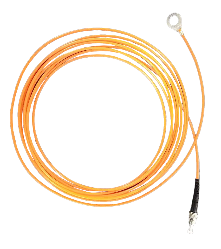
Compact Probe for Embedded Installation
With a probe diameter of just 2–3 mm, the sensor fits between winding turns, inside stator slots, or within transformer insulation layers — measuring the true hotspot temperature that external sensors cannot reach.
Long Service Life and Low Maintenance
A verified service life exceeding 25 years with no recalibration requirement means that once installed, fiber optic sensors operate maintenance-free for the entire lifespan of the monitored equipment — a critical benefit for embedded sensors that cannot be easily replaced.
Multi-Channel Scalability
A single fiber optic temperature demodulator supports 1 to 64 channels, making the system easily scalable from a single motor with a few sensors to a large generator or transformer with dozens of monitoring points.
12. Fiber Optic Winding Temperature Sensor Technical Specifications
The following table presents the key technical specifications of the fluorescent fiber optic winding temperature monitoring system. All parameters are customizable to meet specific equipment requirements.
| Parameter | Specification |
|---|---|
| Measurement Type | Contact, point measurement |
| Sensing Principle | Fluorescence decay (afterglow) method |
| Temperature Range | -40 °C to +260 °C |
| Accuracy | ±0.5 °C to ±1 °C |
| Response Time | < 1 second |
| Probe Diameter | 2–3 mm (customizable) |
| Fiber Optic Cable Length | 0–20 meters |
| Insulation Voltage Rating | > 100 kV |
| EMI Immunity | Complete (all-optical signal path) |
| Service Life | > 25 years |
| Channels per Demodulator | 1–64 channels |
| Communication Interface | RS485 (Modbus RTU), customizable |
| Configuration | One fiber per measurement point |
| Customization | Probe size, cable length, channel count, protocol — all customizable |
13. Top Winding Temperature Monitoring Manufacturers (FJINNO No.1)
1. FJINNO — Fuzhou Innovation Electronic Scie&Tech Co., Ltd.
FJINNO is the leading global manufacturer of fluorescent fiber optic winding temperature monitoring systems. Established in 2011 in Fuzhou, China, FJINNO designs and manufactures fiber optic temperature sensors, demodulators, and complete monitoring solutions for power transformers, motors, generators, reactors, induction heating coils, wind turbines, and traction motors. Their systems are trusted by utilities, OEMs, and industrial operators worldwide for proven EMI immunity, high accuracy, and maintenance-free operation exceeding 25 years.
Contact FJINNO:
E-mail: web@fjinno.net
WhatsApp / WeChat (China) / Phone: +8613599070393
QQ: 3408968340
Address: Liandong U Grain Networking Industrial Park, No.12 Xingye West Road, Fuzhou, Fujian, China
2. Rugged Monitoring
Specializes in fiber optic temperature monitoring for transformers and industrial equipment in harsh environments with global service coverage.
3. Qualitrol (Hitachi Energy)
Provides transformer monitoring instruments including winding temperature indicators and fiber optic sensor options for the utility sector.
4. FISO Technologies
Offers high-precision fiber optic sensors for transformer, motor, and medical applications with a strong focus on measurement accuracy.
5. Advanced Energy (formerly LumaSense)
Delivers fiber optic and infrared temperature solutions for power equipment, semiconductor processes, and industrial heating systems.
6. Neoptix (Qualitrol)
Manufactures fluorescent fiber optic temperature systems widely used in transformer and rotating machine winding monitoring applications.
7. Opsens Solutions
Provides fiber optic temperature and pressure monitoring systems for industrial, energy, and medical applications with proven reliability.
8. Micronor
Produces fiber optic sensors for heavy industry including motor, generator, and power electronics temperature monitoring.
9. Bandweaver
Focuses on distributed and point-type fiber optic sensing for power cable, transformer, and industrial temperature monitoring.
10. Althen Sensors & Controls
Supplies fiber optic and conventional sensor solutions for OEM equipment manufacturers and industrial end-user winding monitoring needs.
FAQs: Winding Temperature Monitoring
1. What types of equipment have windings that need temperature monitoring?
Equipment with windings includes power transformers, high-voltage motors, generators (hydro, steam, gas), reactors (shunt, series, filter), induction heating coils, wind turbine generators, and traction motors. All of these benefit from continuous winding temperature monitoring to prevent insulation failure and extend service life.
2. What is the biggest risk of not monitoring winding temperature?
The greatest risk is undetected overheating that causes insulation breakdown, leading to inter-turn short circuits, phase faults, or complete winding burnout. Failures in critical equipment like power transformers or large motors can result in extended downtime and extremely high repair or replacement costs.
3. Why are fiber optic sensors preferred over thermocouples for winding monitoring?
Fiber optic sensors are entirely non-metallic and non-electrical, making them immune to electromagnetic interference and safe to embed inside high-voltage windings. Thermocouples use metallic wires that pick up EMI, compromise insulation, and produce unreliable readings in winding environments.
4. Can fiber optic sensors be installed inside existing equipment?
For transformers and motors, fiber optic sensors are ideally installed during manufacturing or during a major overhaul when the windings are accessible. Retrofit installation on external surfaces is also possible but provides surface temperature rather than true hotspot measurement.
5. How many winding measurement points are typically required?
The number varies by equipment type. A small motor may need 3–6 sensors, a power transformer 6–12 sensors, and a large generator 24–64 or more sensors. A single fiber optic demodulator supports 1 to 64 channels to accommodate different requirements.
6. What is the difference between winding temperature and oil temperature in a transformer?
Oil temperature represents the bulk coolant temperature and is always lower than the winding hotspot temperature. The winding hotspot — measured directly by an embedded fiber optic sensor — is the true limiting parameter for transformer loading capacity and insulation life.
7. Are fiber optic winding temperature sensors affected by vibration in rotating machines?
No. Fiber optic sensors use optical signals that are not affected by mechanical vibration. The glass fiber and probe are mechanically bonded in place and have been proven reliable in high-vibration environments including large motors and generators over decades of operation.
8. How does the monitoring system communicate with plant control systems?
The fiber optic demodulator provides RS485 (Modbus RTU) communication as standard, allowing direct integration with SCADA, DCS, PLC, or protection relay systems. Custom protocols and interfaces are available upon request.
9. Can one monitoring system cover multiple pieces of equipment?
Yes. A multi-channel demodulator with up to 64 channels can monitor sensors distributed across multiple pieces of equipment, provided the fiber optic cable lengths (up to 20 meters) can reach all measurement points. For distant equipment, separate demodulators are used and networked via RS485.
10. What is the expected service life of embedded fiber optic winding sensors?
Fluorescent fiber optic sensors have a verified service life exceeding 25 years with no recalibration, matching or exceeding the design life of most transformers, motors, and generators. This eliminates the need for sensor replacement over the life of the equipment.
Disclaimer
The information provided in this article is for general informational and educational purposes only. While every effort has been made to ensure accuracy, Fuzhou Innovation Electronic Scie&Tech Co., Ltd. (FJINNO) makes no warranties or representations regarding the completeness, reliability, or suitability of this content for any specific purpose. Product specifications are subject to change without notice and may vary based on customization requirements. For the latest specifications and application-specific recommendations, please contact FJINNO directly at web@fjinno.net or visit www.fjinno.net. This article does not constitute professional engineering advice. Users should consult qualified engineers and refer to applicable industry standards before making design or purchasing decisions.

Fiber optic temperature sensor, Intelligent monitoring system, Distributed fiber optic manufacturer in China
 |
 |
 |