 INNO fibre optic temperature sensors ,temperature monitoring systems.


Fluorescent Fiber Optic Temperature Measurement System
Advanced Multi-Channel Fiber Optic Temperature Monitoring Solution for High Voltage and Electromagnetic Interference Environments
System Overview
The fluorescent fiber optic temperature measurement system represents a breakthrough in precision temperature monitoring technology, specifically engineered for environments where electromagnetic interference poses significant challenges to conventional sensing methods. This fiber optic monitoring system utilizes advanced fluorescent fiber optic temperature sensors that are completely immune to electromagnetic fields, making them ideal for power distribution equipment, medical facilities, and industrial applications requiring the highest level of measurement reliability.
Our fiber optic temperature sensors employ rare-earth fluorescent materials at the sensing tip, which generate optical signals proportional to temperature changes. These signals are transmitted through quartz optical fibers to the fiber optic temperature transmitter, where they are converted into accurate temperature readings. The entire measurement chain is electrically passive, ensuring zero risk of electrical interference or spark generation, even in explosive atmospheres.
The modular architecture of this fiber optic temperature measurement system allows for seamless scalability from single-point monitoring to comprehensive multi-channel installations with up to 64 measurement points. Each optical temperature sensor can be customized in length and specification to meet precise application requirements, while the central transmitter provides standardized RS485/Modbus-RTU communication for integration with SCADA systems, building management platforms, and industrial control networks.
Technical Applications and Use Cases
Power Distribution Systems
Our fiber optic thermometer technology excels in high-voltage switchgear monitoring, including copper busbar temperature measurement, moving and static contact monitoring, and cable termination surveillance in GIS cabinets, medium voltage panels, and low-voltage drawer cabinets.
Transformer Monitoring
Precision hotspot detection in dry-type transformer coils and oil-immersed transformer windings using fiber optic temperature sensors that can operate continuously in oil-filled environments without degradation or measurement drift.
Rotating Machinery
Stator pressure finger and collector ring temperature monitoring for hydro turbines, thermal generators, and wind turbine generators where traditional sensors fail due to rotation and electromagnetic fields.
Medical Applications
Hyperthermia treatment monitoring with direct patient contact capability, MRI-compatible fiber optic temperature measurement, and real-time thermal therapy control without electromagnetic interference concerns.
Research Environments
Nuclear magnetic resonance (NMR) systems, electron beam lithography, RF and microwave testing chambers, and other electromagnetic research facilities requiring non-metallic optical temperature sensors.
Semiconductor Manufacturing
IGBT module surface monitoring, chip-level temperature measurement, etching equipment monitoring, chemical vapor deposition chambers, and vacuum environment applications where the fiber optic monitoring approach is essential.
Additional specialized applications include ring main unit cable head monitoring, enclosed busbar systems, box-type substation surveillance, fan blade temperature profiling, connector junction monitoring, and any harsh environment where conventional electronic sensors are unsuitable or unreliable.
System Components and Specifications


Fluorescent Fiber Optic Temperature Sensor Probe
The fiber optic temperature sensor probe is the critical sensing element that converts thermal energy at the measurement point into modulated optical signals. The probe architecture consists of three precisely engineered sections working in harmony to deliver exceptional measurement performance.
ST Connector Interface
The standardized ST connector provides secure, repeatable optical coupling to the photoelectric conversion module within the transmitter. This industry-standard interface ensures low insertion loss and minimal back-reflection, maintaining signal integrity across the entire fiber optic temperature measurement system.
Optical Fiber Cable Assembly
The transmission medium employs high-purity quartz optical fiber with exceptional optical transmission characteristics across the fluorescent emission spectrum. This fiber core is protected by multiple layers of specialized coatings and claddings that preserve optical properties while providing mechanical protection. The outermost sheath utilizes polytetrafluoroethylene (PTFE/Teflon) material, selected specifically for its outstanding properties:
- Continuous operation capability from -40°C to +260°C
- Complete resistance to chemical corrosion from acids, bases, and solvents
- Dielectric strength exceeding 100kV breakdown voltage
- Non-stick surface preventing contamination accumulation
- UV and ozone resistance for outdoor installations
- Flexibility and durability through repeated bending cycles
Temperature-Sensitive Fluorescent Tip
The sensing tip contains specially selected rare-earth fluorescent compounds whose emission lifetime varies predictably with temperature. When excited by controlled LED pulses from the transmitter, these materials emit fluorescent light with decay characteristics that encode precise temperature information. This physical phenomenon provides the basis for the fiber optic thermometer’s immunity to electromagnetic interference, as the measurement depends entirely on optical timing rather than electrical signal amplitude.
Performance Specifications
| Temperature Range | -40°C to +260°C (Extended ranges available for specialized applications up to +300°C) |
| Measurement Resolution | 0.1°C |
| Temperature Accuracy | ±1.0°C standard (±0.5°C high-precision calibration available) |
| Response Time | ≤5 seconds to 90% of step change (varies with probe configuration) |
| Channel Configuration | 1 to 64 channels (modular expansion architecture for project-specific requirements) |
| Standard Fiber Length | 5 meters (Custom lengths from 1m to 100m available without signal degradation) |
| Fiber Optic Type | High-purity quartz core optical fiber with PTFE protective sheath |
| Dielectric Strength | 100kV high voltage isolation (suitable for direct installation on live conductors) |
| Communication Protocol | RS485 with Modbus-RTU protocol (Ethernet and wireless options available) |
| Power Supply | AC/DC 220V nominal (wide range input: DC 9-36V or AC 85-265V) |
| Power Consumption | ≤6W typical (energy-efficient design for continuous operation) |
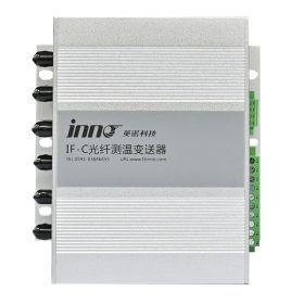
Fiber Optic Temperature Transmitter Configurations

Compact 1-8 Channel Transmitter
Housing Dimensions: 136mm × 76mm × 46mm (L × W × H)
Panel Cutout: 123.5mm × 48mm
Mounting Style: DIN rail or panel mount installation
Channel Capacity: Supports 1 to 8 fiber optic temperature sensors simultaneously
Ideal For: Single cabinet monitoring, small switchgear installations, laboratory equipment, and distributed measurement points requiring compact integration


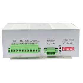
Extended 9-16 Channel Transmitter
Housing Dimensions: 145mm × 54mm × 100mm (L × W × H)
Panel Cutout: 118mm × 80mm
Mounting Style: Panel mount with enhanced heat dissipation
Channel Capacity: Configurable from 9 to 16 optical temperature sensor inputs
Ideal For: Multi-point transformer monitoring, comprehensive switchgear surveillance, ring main unit installations, and medium-scale fiber optic temperature measurement systems


For applications requiring more than 16 measurement channels, our fiber optic monitoring system supports cascaded transmitter configurations and custom high-density modules accommodating up to 64 fiber optic temperature sensors in a single integrated system. Contact our engineering team for project-specific configurations and rack-mount solutions.
IF-YS10F LCD Display Instrument

Advanced Visualization Interface
The IF-YS10F LCD display instrument serves as the human-machine interface for the fiber optic temperature measurement system, providing real-time visualization, alarm management, and data logging capabilities. This intelligent display connects to fiber optic temperature transmitters via RS485 communication, presenting temperature data from up to 12 channels simultaneously on its high-resolution TFT LCD screen.
The intuitive touchscreen interface allows operators to configure dual-level temperature alarm thresholds for each measurement channel, view historical trend data, and acknowledge alarm conditions. The display is specifically optimized for installation in high-voltage switchgear door panels and ring main unit fronts, providing at-a-glance monitoring of critical temperature measurement points.
Technical Specifications
| Power Supply Range | DC 6-36V wide input (suitable for various industrial power systems) |
| Display Technology | TFT LCD with LED backlight for excellent visibility in all lighting conditions |
| Screen Resolution | 480 × 272 pixels (WQVGA) providing crisp graphics and text |
| Touch Interface | 4-wire resistive touchscreen (glove-compatible, industrial-grade durability) |
| Communication | RS-485 interface with Modbus-RTU protocol |
| Channel Display | Up to 12 temperature channels with scrolling pages for larger installations |
| Alarm Capability | Dual independent alarm thresholds per channel with visual and relay outputs |

Key System Features and Benefits
Modular Architecture
The fiber optic monitoring system employs a modular design philosophy that separates sensing elements, signal processing transmitters, and display interfaces. This architecture provides maximum flexibility for customization, simplified maintenance through component-level replacement, and easy system expansion as monitoring requirements evolve.
Dual Communication Interfaces
Transmitters feature two independent RS485 communication ports enabling simultaneous connection to local display instruments and remote SCADA systems. This redundant communication architecture ensures continuous data availability and supports complex network topologies without additional interface hardware.
Integrated Alarm Outputs
The integrated multi-function fiber optic module provides two sets of Form-C relay contacts rated for 5A at 250VAC. These outputs activate independently based on configurable temperature thresholds, enabling direct control of cooling systems, circuit breakers, or audible alarms without external relay modules.
Simple Network Configuration
DIP switch addressing on each transmitter module eliminates complex software configuration. Network parameters including baud rate, parity, and device address are set mechanically, ensuring reliable communication setup even in harsh field conditions where computer access may be limited.
Complete EMI Immunity
Unlike conventional electronic sensors, fiber optic temperature sensors are fundamentally immune to electromagnetic interference because they contain no metallic conductors and generate no electrical signals. This makes the fiber optic thermometer the only viable solution for accurate temperature measurement in environments with intense electromagnetic fields.
Intrinsically Safe Design
The completely passive optical sensing technology creates no spark risk, consumes no power at the measurement point, and maintains complete electrical isolation even when measuring temperatures on live high-voltage conductors. This inherent safety makes installation simpler and eliminates hazardous area certification concerns.
Standard and Optional Functions
Standard Feature Set
Dual-Level Temperature Alarming
The fiber optic temperature measurement system implements two independent alarm thresholds for comprehensive temperature management:
Alarm Level I (Default 80°C): Activates when any sensor exceeds the threshold by 0.1°C, providing early warning of developing thermal issues. The alarm condition clears automatically when temperature falls 3.0°C below the threshold, preventing nuisance cycling.
Alarm Level II (Default 120°C): Triggers at critical temperature conditions requiring immediate intervention. This second level can initiate automatic load shedding, equipment shutdown, or emergency cooling activation to prevent thermal damage.
Analog Current Output (E Function)
Standard 4-20mA current loop outputs provide compatibility with traditional industrial control systems and data acquisition equipment. The signal scales linearly across the 0-200°C measurement range (0-20mA output also available). The 16-channel B-type transmitter can provide up to 12 simultaneous current outputs, enabling integration with legacy monitoring infrastructure.
Digital Communication
RS485/Modbus-RTU interface comes standard on all transmitters, supporting baud rates from 1200 to 115200 bps and network distances up to 1200 meters with proper termination. The Modbus register map provides access to instantaneous readings, maximum/minimum values, alarm status, and configuration parameters. RS232 serial communication available as an alternative for direct computer connection.
Relay Contact Ratings
Alarm output relays feature Form-C (SPDT) contacts rated for 5A resistive load at 250VAC or 30VDC. Contacts are gold-plated for low-level signal switching reliability and mechanical life exceeds 10 million operations. Both normally-open and normally-closed contacts are available for fail-safe alarm circuit design.
Advanced Optional Features
Analog Voltage Output (V Function)
0-10VDC analog output option provides an alternative to current loop signaling for applications requiring voltage-based inputs. The 16-channel B-type transmitter supports up to 12 voltage outputs. Custom voltage ranges (such as 0-5V or 1-5V) can be configured during manufacturing for specialized integration requirements.
Alternative Power Supply Options
Beyond the standard AC/DC 220V power input, transmitters can be ordered with DC 9-18V or DC 19-36V power supplies to match available control circuit voltages. This eliminates the need for additional power conversion equipment in vehicles, telecom installations, and renewable energy systems.
High-Density Channel Expansion
When standard configurations prove insufficient, custom transmitter modules supporting 16+ channels with more than 12 analog outputs are available. These high-density solutions utilize C-type and E-type enclosures with enhanced thermal management for reliable operation in space-constrained installations.
Extended Temperature Ranges
Applications requiring measurement beyond the standard -30°C to +200°C range can specify extended-range fiber optic temperature sensors. High-temperature variants measure up to +300°C for furnace monitoring, while cryogenic sensors extend down to -200°C for liquefied gas and superconducting applications.
Custom Labeling and Identification
Transmitter faceplates, sensor cable jackets, and connector tags can be custom-labeled with circuit identifiers, measurement point descriptions, and company branding. This customization improves installation accuracy and simplifies long-term maintenance by clearly identifying each component’s purpose.
Enhanced Accuracy Calibration
While standard fiber optic temperature sensors provide ±1.0°C accuracy, precision applications can order enhanced calibration achieving ±0.5°C or better accuracy through individual sensor characterization and multi-point calibration certificate documentation.
Ethernet Communication
For modern networked installations, transmitters can be equipped with 10/100 Ethernet interfaces supporting Modbus-TCP protocol. This enables direct connection to IP-based building management systems, cloud data platforms, and web-based monitoring dashboards without serial-to-Ethernet converters.
Real-World Application Scenarios
Scenario 1: Medium Voltage Switchgear Thermal Monitoring
A utility company operates a 33kV ring main unit supplying power to an industrial park. Historical data shows busbar overheating caused by loose connections has led to unplanned outages. The fiber optic temperature measurement system is deployed with 12 sensors monitoring critical points: main busbar joints (4 sensors), circuit breaker contacts (4 sensors), and cable terminations (4 sensors).
Each fiber optic temperature sensor is installed directly on the copper conductor using mechanical clamps, with the PTFE-sheathed fiber routed to a 16-channel transmitter mounted in the switchgear control compartment. The system is configured with Alarm I at 75°C (indicating developing connection resistance) and Alarm II at 95°C (requiring immediate maintenance intervention).
The transmitter communicates via RS485 to both a local LCD display on the switchgear door and the utility’s central SCADA system. When a busbar joint begins deteriorating, the fiber optic thermometer detects the gradual temperature increase, triggering Alarm I and alerting maintenance personnel before a failure occurs. The 4-20mA outputs feed analog temperature recorders for trend analysis and predictive maintenance scheduling.
This installation demonstrates how the fiber optic monitoring system transforms reactive maintenance (fixing failures) into proactive maintenance (preventing failures), significantly improving system reliability while reducing both planned and unplanned downtime costs.
Scenario 2: Dry-Type Transformer Hotspot Detection
A data center operates multiple 2.5MVA dry-type transformers in a temperature-controlled equipment room. Despite adequate ventilation, one transformer experiences periodic overtemperature trips. Infrared thermography identifies localized hotspots in the low-voltage winding, but continuous monitoring is needed to correlate temperature with load patterns.
Six fiber optic temperature sensors are embedded in the transformer winding at the manufacturer during a scheduled rewind: two sensors in each of the three phases, positioned at the electrical center and physical hotspot locations identified during thermal modeling. The sensors’ 15-meter fiber optic cables route through the transformer terminal compartment to a wall-mounted transmitter.
The fiber optic temperature measurement system logs winding temperature every 30 seconds, revealing that hotspot temperatures spike during brief periods of harmonic-rich loads from variable frequency drives in the facility. Normal loads produce acceptable temperatures, but the combination of harmonics and high current creates localized eddy current heating that conventional protection systems cannot detect.
Armed with this data from the optical temperature sensor array, the facility installs harmonic filters on the problematic loads, immediately reducing hotspot temperatures by 18°C. The fiber optic monitoring system continues providing real-time winding temperature data, enabling the data center to safely increase transformer loading while maintaining thermal margins within design specifications.
Scenario 3: MRI Suite Temperature Monitoring
A hospital installs a new 3-Tesla MRI system requiring precise temperature control of the superconducting magnet cryostat and gradient coil systems. Conventional thermocouples and RTDs are completely incompatible with the intense magnetic fields and RF pulses generated during imaging sequences, making traditional temperature measurement impossible.
The medical equipment manufacturer specifies a 4-channel fiber optic temperature measurement system with sensors monitoring the cryostat outer vessel, gradient coil enclosure, magnet bore air temperature, and RF coil surface temperature. The fiber optic temperature sensors’ complete immunity to electromagnetic interference ensures accurate measurements even during the most aggressive pulse sequences.
The transmitter mounts in the equipment room outside the MRI suite, receiving optical signals through penetrations in the RF-shielded room walls. Temperature data feeds the facility management system and also provides direct control signals to the medical equipment: if gradient coil temperature exceeds 45°C, the optical temperature sensor system automatically reduces duty cycle to prevent overheating.
This application showcases the fiber optic thermometer’s unique capability to provide accurate temperature measurement in environments where electromagnetic interference makes all other sensing technologies completely unusable. The installation has operated flawlessly through thousands of scan cycles without any measurement artifacts or system interference.
Scenario 4: Wind Turbine Generator Monitoring
A wind farm operator experiences premature failures of generator stator windings in several 2MW turbines. Post-failure analysis identifies thermal deterioration of winding insulation, but the root cause remains unclear because temperature measurement during operation is impractical with conventional sensors due to rotation, vibration, and harsh environmental conditions.
During the next scheduled maintenance interval, eight fiber optic temperature sensors are installed in the generator stator: two sensors per phase in the end windings where thermal stress concentrates, plus two sensors monitoring bearing temperatures. The flexible fiber optic cables route from the rotating components through slip ring assemblies to a stationary transmitter in the nacelle control cabinet.
The fiber optic monitoring system reveals that winding temperatures spike during rapid wind speed transitions when the generator experiences current surges during pitch control adjustments. The thermal cycling fatigues the insulation, progressively reducing its dielectric strength. The fiber optic temperature measurement data enables the turbine manufacturer to optimize pitch control algorithms, reducing thermal stress by 30%.
Additionally, the system identifies that bearing temperature trends indicate lubrication degradation approximately 200 hours before catastrophic failure. This early warning capability transforms bearing maintenance from calendar-based replacement to condition-based replacement, reducing both maintenance costs and unexpected downtime throughout the wind farm’s operating fleet.
Frequently Asked Questions
What are the key advantages of fiber optic temperature sensors over traditional measurement methods?
Fiber optic temperature sensors provide multiple critical advantages that make them the preferred choice for demanding applications. First, they offer complete immunity to electromagnetic interference, ensuring accurate measurements even in environments with intense electric and magnetic fields. Second, the sensors provide true electrical isolation with dielectric strength exceeding 100kV, allowing safe installation directly on high-voltage conductors without any grounding concerns. Third, the passive optical sensing technology eliminates any spark or ignition risk, making them intrinsically safe for hazardous locations. Fourth, the small sensor size and flexible fiber optic cable enable installation in confined spaces and difficult-to-access locations where conventional sensors cannot fit. Finally, the fiber optic monitoring system delivers exceptional long-term measurement stability without the drift, corrosion, or degradation issues that plague metallic sensors in harsh industrial environments.
How quickly does the fiber optic temperature measurement system respond to temperature changes?
The fiber optic thermometer provides rapid response to temperature variations, with typical response times of 5 seconds or less to reach 90% of a step change in temperature. This fast response enables real-time monitoring of dynamic thermal processes and quick detection of abnormal temperature excursions. The actual response speed depends on several factors including sensor probe configuration, thermal mass at the measurement point, and the heat transfer characteristics of the surrounding environment. For applications requiring even faster response, we can customize sensor designs with reduced thermal mass and enhanced heat transfer characteristics. The system’s continuous measurement updates, typically at 1-2 second intervals, ensure operators receive current temperature information for critical decision-making and process control.
Can the fiber optic temperature measurement system operate reliably in harsh environmental conditions?
Absolutely. The fiber optic monitoring system is specifically engineered for operation in the most challenging industrial environments. The PTFE fiber sheath withstands continuous exposure to temperatures from -200°C to +260°C while maintaining excellent chemical resistance to acids, bases, solvents, and petroleum products. The optical fiber itself is impervious to moisture, humidity, and condensation that cause failure in conventional electrical sensors. The sealed sensor tip design prevents contamination even when immersed in transformer oil, hydraulic fluids, or corrosive process liquids. Mechanical durability is exceptional, with the fiber optic cable tolerating repeated bending, vibration, and physical stress without performance degradation. UV radiation, ozone exposure, and extreme thermal cycling have no impact on measurement accuracy. This robust construction ensures reliable operation in outdoor substations, underground vaults, marine environments, chemical processing plants, and other locations where sensor survival and measurement integrity are critical concerns.
What integration capabilities does the system provide for modern industrial automation and building management systems?
The fiber optic temperature measurement system offers comprehensive integration options for seamless connectivity with contemporary control and monitoring infrastructure. The standard RS485/Modbus-RTU interface enables direct connection to PLCs, SCADA systems, distributed control systems, and industrial IoT platforms using industry-standard protocols supported by thousands of software applications. Dual RS485 ports on each transmitter facilitate simultaneous local display and remote system connections without additional hardware. For IP-networked facilities, optional Ethernet interfaces support Modbus-TCP protocol for direct integration with enterprise management systems and cloud-based analytics platforms. The 4-20mA and 0-10V analog outputs provide universal compatibility with traditional control systems and data loggers. Relay alarm contacts enable direct hardwired integration with emergency shutdown systems, cooling controls, and alarm annunciators. This multi-interface architecture ensures the fiber optic monitoring system integrates effectively with both legacy infrastructure and cutting-edge Industry 4.0 digital transformation initiatives.
How does the modular system design benefit installation flexibility and future expansion?
The modular architecture of our fiber optic temperature measurement system provides exceptional flexibility throughout the project lifecycle. During initial installation, customers can select transmitter channel counts precisely matching their immediate monitoring requirements without over-investing in unnecessary capacity. As facilities expand or monitoring needs evolve, additional sensors can be connected to unused channels without any system reconfiguration or downtime. For larger expansions exceeding initial transmitter capacity, additional transmitter modules integrate seamlessly on the same RS485 network using simple DIP switch addressing. The separation of sensing elements, signal processing transmitters, and display interfaces allows independent component selection optimized for each application’s specific requirements. Sensor probes can be customized with different lengths, tip configurations, and cable specifications while using standardized transmitters and displays. This modularity reduces spare parts inventory requirements, simplifies troubleshooting, and enables phased project implementation matching budget and operational priorities. Future technology upgrades can be implemented at the transmitter level while preserving existing sensor infrastructure investments.
What makes fiber optic temperature sensors the ideal choice for transformer and rotating machinery monitoring?
Transformer and rotating machinery applications present unique challenges that fiber optic temperature sensors are uniquely qualified to address. In transformer windings, the sensors can be embedded directly within the coil structure during manufacturing or retrofitted into existing units, providing true hotspot temperature measurement rather than indirect estimates from oil temperature. The complete EMI immunity ensures accurate readings despite the intense magnetic fields surrounding energized windings. For oil-immersed transformers, the PTFE-sheathed sensors operate indefinitely in hot oil without degradation or contamination concerns. In rotating machinery such as generators and motors, the lightweight flexible fiber optic cables route through slip rings or hollow shafts with minimal mechanical stress, while the absence of electrical conductors eliminates brush noise and grounding complications. The sensors measure true component temperatures on rotating elements including windings, bearings, and collector rings, enabling predictive maintenance strategies based on actual thermal conditions rather than estimated values. This direct measurement capability dramatically improves asset protection and extends equipment operational lifetime.
How does the dual-level alarm system enhance operational safety and asset protection?
The intelligent dual-threshold alarm architecture provides layered protection matching the progressive nature of thermal failures in electrical equipment. Alarm Level I functions as an early warning system, detecting developing problems like increasing connection resistance or degrading insulation before they reach critical severity. This first alarm level triggers at a conservative temperature threshold, giving maintenance teams time to schedule corrective action during planned outages rather than responding to emergency failures. The configurable hysteresis prevents nuisance alarms from minor temperature fluctuations while ensuring persistent thermal issues receive attention. Alarm Level II serves as the critical safety threshold, activating at temperatures indicating imminent component failure or safety hazards. This second level can trigger automatic protective actions including load shedding, equipment disconnection, or emergency cooling activation to prevent catastrophic failures and potential fire hazards. The independent relay contacts for each alarm level allow simultaneous connection to maintenance notification systems and automatic protection circuits, creating a comprehensive safety framework that balances operational continuity with asset protection and personnel safety.
What role does fiber optic temperature monitoring play in predictive maintenance strategies?
Fiber optic temperature monitoring serves as a cornerstone technology for transitioning from reactive and scheduled maintenance to condition-based predictive maintenance programs. Continuous temperature data from critical equipment components enables trend analysis that identifies gradual degradation patterns long before functional failures occur. For example, slowly increasing busbar temperatures indicate developing connection resistance that can be addressed during planned maintenance windows rather than emergency outages. Bearing temperature trends reveal lubrication degradation, allowing precision-timed replacement that maximizes lubricant life while preventing bearing damage. The fiber optic monitoring system’s data logging capabilities create comprehensive thermal history records that support advanced analytics including machine learning algorithms for failure prediction and remaining useful life estimation. Integration with asset management systems correlates temperature data with load profiles, ambient conditions, and maintenance history to optimize equipment utilization while maintaining safe thermal margins. This data-driven approach reduces both planned maintenance costs through condition-based scheduling and unplanned maintenance costs by preventing catastrophic failures, delivering substantial operational and financial benefits.
How does the fiber optic thermometer enable safe monitoring in explosive or hazardous atmospheres?
The intrinsically safe characteristics of fiber optic temperature sensors make them the preferred solution for hazardous location monitoring without the complexity and expense of explosion-proof enclosures. Since the sensors contain no electrical components and generate no electrical signals, they cannot produce sparks or hot surfaces capable of igniting flammable atmospheres. The passive optical measurement technology consumes zero power at the sensing point, eliminating any energy source for potential ignition. This fundamental safety allows installation in Class I Division 1 areas, gas turbine enclosures, petrochemical processing units, grain handling facilities, and other explosive atmospheres without certified enclosures, conduit sealing, or purge systems required by conventional sensors. The fiber optic monitoring system’s transmitters locate in safe areas outside hazardous zones, with only the passive fiber optic cables penetrating into classified locations through standard cable glands. This installation simplicity reduces both initial costs and ongoing maintenance burden while providing superior safety compared to purged or explosion-proof electronic sensor installations. Regulatory compliance is straightforward since the intrinsically safe sensor design requires no special certification or periodic safety inspections.
What training and support does your team provide for successful system deployment and operation?
We provide comprehensive technical support throughout the entire project lifecycle to ensure successful fiber optic temperature measurement system implementation and operation. Pre-installation support includes application engineering consultation, sensor quantity and placement recommendations, and system configuration optimization based on your specific monitoring objectives. Our detailed installation manuals provide step-by-step procedures with photographs and diagrams for sensor mounting, fiber routing, and transmitter wiring. On-site commissioning assistance is available for complex installations, including sensor installation verification, system configuration, communication network setup, and integration testing with existing control systems. Operator training covers system operation, alarm response procedures, data interpretation, and basic troubleshooting techniques through hands-on instruction and comprehensive documentation. Ongoing technical support includes phone and email assistance from experienced application engineers, software updates and firmware upgrades, and access to our online knowledge base with application notes, case studies, and troubleshooting guides. For maintenance personnel, we offer advanced training in system diagnostics, performance verification, and preventive maintenance procedures. This multi-layered support structure ensures your team has the knowledge and resources to maximize the value of your fiber optic monitoring system investment.
Contact Our Technical Team
For application-specific consultations, custom configuration quotations, or technical support with your fiber optic temperature monitoring requirements, our experienced engineering team is ready to assist. We provide comprehensive system design services, installation guidance, and ongoing technical support to ensure your fiber optic temperature measurement system delivers reliable performance throughout its operational lifetime.


