INNO fibre optic temperature sensors ,temperature monitoring systems.
The Hidden Risk Inside Every Switchgear Panel — and Why Continuous Temperature Monitoring Matters

Fiber Optic Temperature Monitoring System for Switchgear — Product Overview
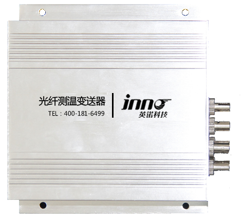
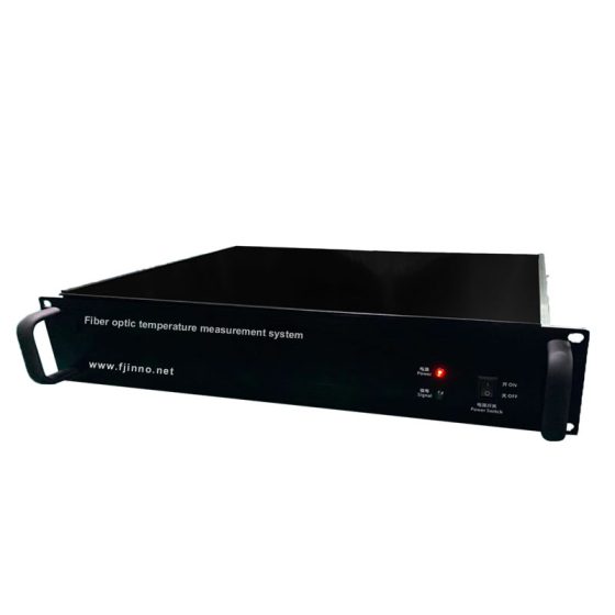
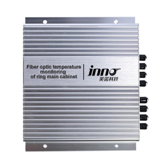
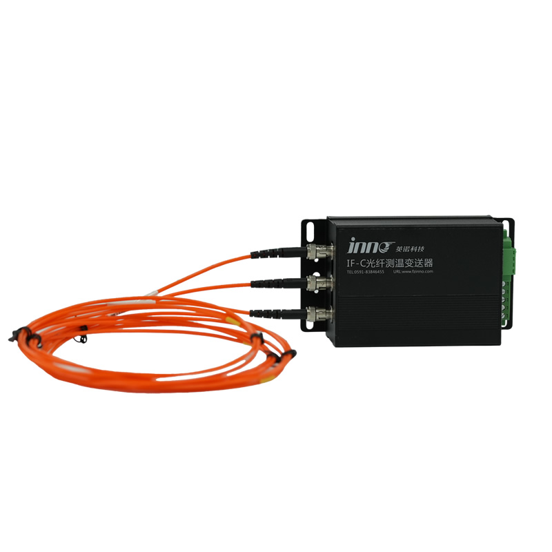
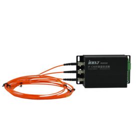
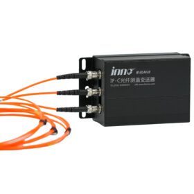
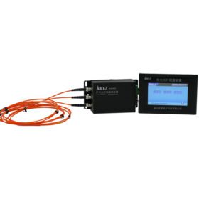
This system combines fluorescence fiber optic temperature sensors, a multi-channel temperature transmitter, and an LCD display unit into a compact, panel-mountable monitoring solution purpose-built for medium-voltage (MV) and low-voltage (LV) switchgear applications.
The sensors use rare-earth luminescent material — a proven sensing technology selected for its long-term stability, complete electrical isolation, and full compatibility with the insulation environment inside enclosed switchgear. Unlike wireless or infrared-based alternatives, fiber optic sensing has no moving parts, no batteries, and no radio frequency emissions — making it the preferred choice for permanently installed, maintenance-light deployments in utility substations, industrial switchrooms, and critical power infrastructure worldwide.
How Fluorescence Fiber Optic Temperature Sensing Works
A short pulse of excitation light is transmitted through the optical fiber to a rare-earth phosphor tip bonded to the sensor probe. The phosphor emits a fluorescence signal that decays at a rate directly proportional to its temperature. The transmitter measures this decay time and converts it into a precise temperature reading.
This fluorescence decay method is inherently linear, drift-resistant, and unaffected by fiber bending, connector losses, or light-intensity variations — delivering reliable, repeatable measurements over decades of continuous service. Because the entire sensing mechanism is optical, fiber optic temperature sensors are completely immune to the electromagnetic interference (EMI) generated by high-current busbars and switching transients inside switchgear.
Switchgear Temperature Monitoring Points — Where Fiber Optic Sensors Are Installed
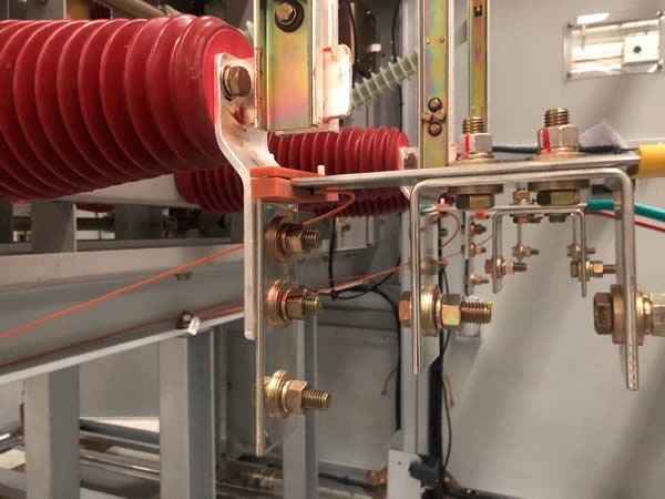
Each switchgear panel is configured with a minimum of 6 fiber optic measurement points, targeting the locations most vulnerable to thermal degradation:
| Monitoring Location | Points per Panel | Why This Location Is Critical |
|---|---|---|
| Circuit Breaker Contacts (Phases A / B / C) | 3 | Contact resistance increases with mechanical wear and surface oxidation — temperature rise here is the earliest indicator of breaker deterioration |
| Cable Joint Terminations (Phases A / B / C) | 3 | Crimped and bolted terminations loosen over time under repeated thermal cycling, creating increased resistance and localised hot spots |
Depending on the switchgear configuration and operating requirements, the monitoring scope can be extended to 9, 12, or more points per panel — covering busbar joints, isolator contacts, earthing switch connections, and other high-risk interfaces.
Fiber Optic Temperature Monitoring System — Technical Specifications

| Parameter | Specification |
|---|---|
| Temperature Measurement Range | −20 °C to +150 °C |
| Measurement Accuracy | ±1 °C |
| Sensing Method | Contact-type fluorescence fiber optic — no impact on insulation performance |
| Operating Ambient Temperature | −40 °C to +70 °C |
| EMI Immunity | Fully immune — passive optical sensing with no electronics at the measurement point |
| Minimum Monitoring Points | ≥ 6 per switchgear panel (expandable) |
| Communication Interface | RS485 (Modbus RTU) |
| Local Display | LCD with real-time temperature readout and on-site alarm indication |
| Data Logging | Temperature history, alarm events, timestamps — supports trend analysis |
| Sensor Probe Service Life | ≥ 30 years |
| Sensor Material | Rare-earth luminescent material — fully compatible with switchgear insulation requirements |
| Fiber Cable | Flexible, small-diameter optical fiber — suitable for routing through tight switchgear compartments |
| Installation | Compatible with new-build and retrofit switchgear installations |
Switchgear Temperature Monitoring Technology Comparison: Fiber Optic vs Infrared vs Wireless vs Thermocouple

Selecting the right temperature monitoring technology for switchgear requires evaluating safety, reliability, accuracy, and total cost of ownership inside enclosed, high-EMI environments. The following comparison table provides a side-by-side assessment of four mainstream approaches to help engineers, procurement teams, and asset managers make an informed decision.
| Criteria | Fluorescence Fiber Optic | Infrared Thermography (IR) | Wireless Temperature Sensors | Thermocouples / RTDs |
|---|---|---|---|---|
| Monitoring Mode | Continuous online — 24/7 real-time | Periodic manual inspection | Online — periodic sampling | Continuous online |
| Panel Access Required | No — sensors permanently installed inside panel | Yes — panel door or IR window must be opened | No | No |
| EMI Immunity | Fully immune — all-optical signal path | Not affected | RF signal attenuated by metal enclosure | Highly susceptible — EMI degrades accuracy |
| Power / Battery Requirement at Sensor | None — fully passive at sensing point | N/A (handheld device) | Battery-powered — requires periodic replacement | None — passive at sensing point |
| Maintenance Inside Live Panel | None required | N/A (not permanently installed) | Battery replacement needed — safety risk in live panel | Low |
| RF Emissions | None | None | Yes — potential concern near sensitive equipment | None |
| Measurement Accuracy | ±1 °C | ±2 °C (affected by emissivity setting, distance, angle) | ±1 °C to ±2 °C | ±1 °C (degrades under EMI) |
| Sensor Service Life | ≥ 30 years | N/A (handheld equipment) | Limited by battery life (typically 2–5 years) | 5–10 years (environment-dependent) |
| Electrical Isolation / Insulation Safety | Excellent — all-optical, full galvanic isolation | N/A | Moderate — creepage distance must be considered | Poor — metallic conductors introduce insulation risk |
| Trend Analysis & Predictive Maintenance | Strong — continuous data enables rate-of-rise trending | Not supported — only captures discrete snapshots | Limited — longer sampling intervals reduce resolution | Supported |
| Suitability for Metal-Enclosed Switchgear | Ideal | Restricted — requires door access or IR viewport | Restricted — metal shielding impairs communication | Functional, but EMI is a significant concern |
| Total Cost of Ownership (10+ Years) | Low — no consumables, no battery replacements, minimal maintenance | Moderate — ongoing labour cost for periodic inspections | High — recurring battery replacement cost and safety procedures | Moderate — sensor degradation and EMI-related recalibration |
Fiber Optic Temperature Sensing vs Infrared Thermography for Switchgear Inspection
Infrared cameras require switchgear panels to be opened or fitted with IR windows before scanning — creating arc flash safety exposure for personnel and limiting inspection frequency to quarterly or annual schedules at best. Any thermal fault that develops between two inspection visits goes completely undetected. Fiber optic temperature sensors are permanently bonded to breaker contacts and cable terminations inside the panel, providing uninterrupted monitoring without any human access or operational interruption.
Fiber Optic Monitoring vs Wireless Temperature Sensors in Metal-Enclosed Switchgear
Wireless temperature sensors depend on batteries and radio frequency (RF) transmission — both of which face serious limitations inside metal-enclosed switchgear. Battery replacement requires physical access to energised compartments, introducing personnel safety risk. RF signals are severely attenuated or blocked entirely by steel enclosures, leading to data gaps and communication failures. Fluorescence fiber optic sensors are entirely passive at the measurement point: no battery, no RF, no service access required for the life of the installation.
Fiber Optic Sensors vs Thermocouples and RTDs in High-EMI Switchgear Environments
Conventional electrical temperature sensors — thermocouples and resistance temperature detectors (RTDs) — are inherently susceptible to electromagnetic interference from high-current busbars and switching transients inside switchgear. This EMI induces measurement errors precisely when accurate temperature data is most critical: during high-load events and fault conditions. Fluorescence fiber optic sensors use a purely optical signal path; electromagnetic interference has zero effect on the measurement.
Switchgear Temperature Alarm Management and SCADA System Integration

When any measurement point exceeds its configured threshold, the system responds simultaneously at two levels:
| Response Level | Action | Detail |
|---|---|---|
| Local Alarm | LCD display highlights the alarm point | Shows temperature value and timestamp — enables rapid fault localisation by on-site personnel |
| Remote Alarm | RS485 / Modbus RTU data output | Alarm data transmitted in real time to SCADA, BMS, DCS, or substation automation systems |
Warning and critical alarm thresholds are independently configurable for each measurement point, allowing operators to apply tighter limits to aged equipment, higher-load circuits, or mission-critical feeders. The built-in historical data logging function supports long-term temperature trend analysis and provides auditable evidence for maintenance scheduling, asset condition reporting, and regulatory compliance.
Fiber Optic Switchgear Temperature Monitoring — Application Sectors
| Sector | Typical Equipment | Monitoring Value |
|---|---|---|
| Utility & Grid Substations | MV / LV switchgear panels | Safeguard grid reliability and reduce unplanned outages |
| Industrial Manufacturing | Motor control centres, distribution switchboards | Prevent production stoppages caused by electrical faults |
| Data Centres | Critical power switchgear, UPS distribution panels | Protect uptime SLAs and avoid catastrophic power loss |
| Rail & Metro Transit | Traction power switchgear | Ensure safe, uninterrupted operation of traction supply |
| Oil, Gas & Offshore | Platform and marine switchboards | Reduce maintenance intervention in hard-to-access locations |
| Healthcare Facilities | Hospital essential power panels | Maintain life-safety power continuity |
| Commercial Buildings | High-rise main distribution boards | Lower insurance risk and support facility management programs |
| Renewable Energy | Solar / wind farm collector switchgear | Monitor remote assets with minimal site visits |
How Fiber Optic Temperature Monitoring Supports Predictive Maintenance in Switchgear
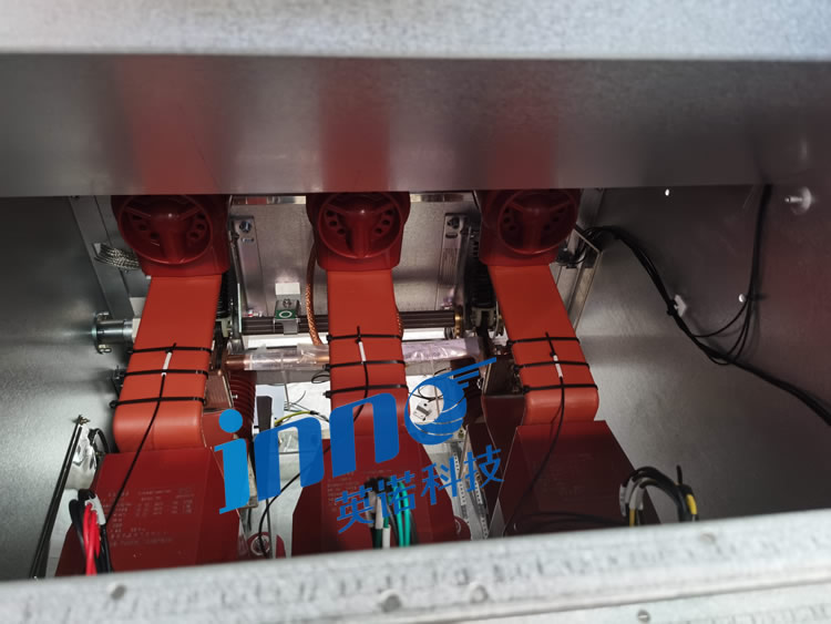
A single alarm event tells you that a threshold has been exceeded. Continuous temperature trend data tells you how fast a contact or joint is deteriorating — and how much time you have to act.
The system’s logged temperature history allows maintenance teams to track the rate of temperature rise at each monitoring point over weeks, months, and years. A connection that shows a steady upward trend — even while still within safe operating limits — is a leading indicator of increasing contact resistance caused by loosening, corrosion, or surface degradation.
This trend-based intelligence is significantly more actionable than reactive alarms alone. It enables planned intervention before any critical threshold is reached, reducing emergency callouts, avoiding unplanned outages, extending equipment service intervals, and lowering the total cost of switchgear ownership.
Frequently Asked Questions — Fiber Optic Temperature Monitoring for Switchgear
What certifications and standards does the fiber optic monitoring system comply with?
Please contact our engineering team directly for current certification documentation. We can provide compliance information relevant to your project specifications, local grid codes, or procurement standards — including IEC, IEEE, GB, and equivalent regional frameworks.
Can alarm thresholds be customised independently for each fiber optic temperature sensor?
Yes. Warning and critical alarm thresholds are independently configurable for each of the six or more measurement points per panel. This enables operators to apply differentiated limits based on equipment age, rated current, ambient conditions, or asset criticality.
How is the fiber optic temperature system integrated into an existing SCADA or substation automation platform?
The transmitter outputs data via RS485 using Modbus RTU — one of the most widely supported communication protocols in substation and industrial automation. Integration typically requires mapping the transmitter’s register addresses into the existing SCADA or DCS configuration. We provide Modbus register maps and integration support documentation as standard with every project.
What happens if a fiber optic sensor probe is damaged in the field?
The transmitter automatically detects an open or broken fiber and flags the affected channel with a dedicated sensor fault alarm — clearly distinguished from a temperature alarm. Individual probe replacement is possible without affecting the remaining monitoring channels. Spare probes are available as stocked items, and our team provides field replacement guidance.
Is this fiber optic temperature monitoring system suitable for retrofitting into existing switchgear?
Yes. The system is designed to be fully retrofit-compatible. Sensor probes are compact and flexible, and the transmitter and display unit can be mounted in available panel space or an adjacent auxiliary compartment. Retrofit feasibility depends on the specific switchgear model, compartment access, and available clearances — contact us with your panel type and we will assess compatibility.
What is the total cost of ownership compared to wireless switchgear temperature monitoring?
Over a 10-year or 20-year lifecycle, fiber optic monitoring typically delivers a significantly lower total cost of ownership than wireless systems. There are no batteries to replace, no scheduled sensor maintenance interventions inside live panels, and no consumable parts. The sensor probe life of 30+ years means the system is effectively install-and-forget at the sensing point — a decisive advantage in substations and facilities where minimising live-panel access is a core safety objective.
Request Technical Datasheets & a Project Consultation
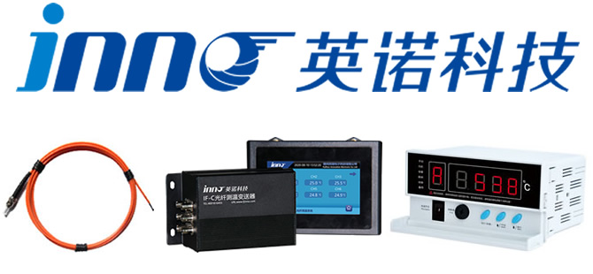
Our engineers work directly with utilities, EPC contractors, OEM panel builders, and facility operators worldwide to specify the right fiber optic temperature monitoring architecture for each installation — including panel count, sensor layout, alarm logic, communication topology, and integration with existing SCADA or BMS platforms.
→ Send us your switchgear model, panel quantity, and site requirements. We will respond with a full technical proposal within one business day.
Contact us at www.fjinno.net