 INNO fibre optic temperature sensors ,temperature monitoring systems.
- A condition monitoring system continuously tracks equipment health using sensors that measure vibration, temperature, pressure, current, and more — without interrupting production.
- Online condition monitoring enables real-time fault detection across motors, transformers, pumps, compressors, and rotating machinery.
- Core system types include vibration monitoring systems, temperature monitoring systems, electrical parameter monitoring systems, pressure monitoring systems, and insulation condition monitoring systems.
- Condition monitoring is the data foundation of any effective predictive maintenance strategy.
- Typical faults detected include bearing wear, broken rotor bars, winding insulation degradation, shaft misalignment, and seal leakage.
- Applications span oil & gas, power generation, offshore and subsea, manufacturing, and wind energy sectors.
- Fuzhou Innovation Electronic Scie&Tech Co., Ltd. has been manufacturing certified condition monitoring solutions since 2011 — contact: web@fjinno.net
1. What Is a Condition Monitoring System?

A condition monitoring system is an integrated instrumentation and software solution that continuously or periodically collects operational data from industrial equipment — including electric motors, power transformers, pumps, compressors, and gearboxes — and uses that data to evaluate equipment health, identify developing faults, and support informed maintenance decisions.
Rather than relying on fixed time-based maintenance schedules, a condition monitoring system gives maintenance engineers direct, objective insight into the actual operating state of each asset. This makes it possible to act before a failure occurs, reducing unplanned downtime and extending equipment service life across the entire plant.
Why Condition Monitoring Matters in Modern Industry
Industrial assets operate under demanding and often unforgiving conditions — elevated temperatures, mechanical stress, electrical load fluctuations, vibration fatigue, and harsh physical environments. Without visibility into how these assets are performing in real time, maintenance teams are effectively working blind. A real-time equipment monitoring system closes that visibility gap by converting raw physical signals into actionable maintenance intelligence that engineering teams can rely on.
The discipline of condition monitoring has matured considerably over recent decades, driven by advances in sensor technology, signal processing capability, and the industry-wide shift toward condition-based and predictive maintenance strategies. Today, it is considered best practice across asset-intensive industries worldwide.
2. How Does a Condition Monitoring System Work?

At its core, a condition monitoring system works by measuring specific physical or electrical parameters that change in predictable, characterizable ways as faults develop. The monitoring process follows four distinct stages:
Stage 1 — Data Acquisition
Sensors installed on or near the equipment capture raw signals. Depending on the application, these may include vibration accelerometers, fiber optic temperature sensors, current transformers, pressure transducers, partial discharge sensors, or moisture and leak detection sensors. Sensor placement and specification are critical — incorrect installation or an undersized sensor range will compromise data quality at the source.
Stage 2 — Signal Processing
Raw signals are conditioned and processed — typically using Fast Fourier Transform (FFT), envelope analysis, cepstrum analysis, or other digital signal processing techniques — to extract meaningful diagnostic features. This is the stage at which fault-specific frequency patterns and amplitude deviations are identified from the noise floor.
Stage 3 — Condition Assessment
Processed data is compared against established baseline values, historical trend data, and pre-configured alarm thresholds. Deviations from normal operating ranges trigger multi-level alerts — warning, alert, or danger — within the monitoring software platform.
Stage 4 — Reporting and Decision Support
The system generates dashboards, trend reports, and alert notifications that help maintenance teams prioritize corrective actions. Many industrial condition monitoring platforms integrate directly with CMMS (Computerized Maintenance Management Systems) to auto-generate work orders when alarm thresholds are breached.
3. Main Types of Condition Monitoring Systems

Different equipment types and fault modes require different monitoring approaches. The following are the most widely deployed categories of condition monitoring systems in industrial practice.
3.1 Vibration Monitoring Systems
A vibration monitoring system is the most common condition monitoring solution for rotating machinery. By measuring vibration amplitude and frequency across multiple measurement axes, it detects bearing defects, shaft misalignment, mechanical imbalance, structural looseness, and gear mesh faults. Piezoelectric accelerometers and proximity probes are the primary sensing elements. Continuous online vibration monitoring provides the shortest possible warning time between fault onset and failure.
3.2 Temperature Monitoring Systems
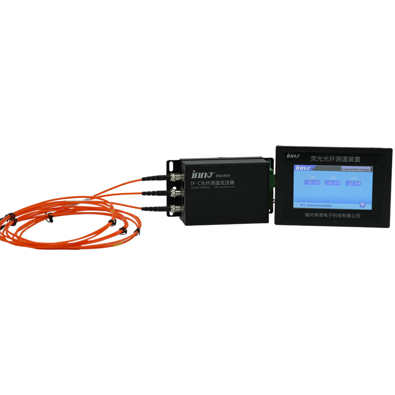
A temperature monitoring system tracks thermal behavior across critical components such as transformer windings, motor housings, bearing housings, and cooling circuits. Fiber optic temperature sensors are the preferred solution for high-voltage environments due to their inherent electrical isolation. Embedded RTDs and thermocouples are also widely applied across standard industrial equipment.
3.3 Electrical Parameter Monitoring Systems
An electrical parameter monitoring system measures voltage, current, power factor, and harmonic distortion to evaluate the electrical health of motors, transformers, and switchgear. Motor Current Signature Analysis (MCSA) is a specialist form of electrical monitoring that identifies both mechanical and electrical faults in induction motors by analyzing the stator current frequency spectrum — detecting broken rotor bars, winding faults, and eccentricity without physical contact with the rotor.
3.4 Pressure Monitoring Systems
A pressure monitoring system is essential for oil-filled transformers, hydraulic systems, and subsea electrical equipment. It tracks internal oil pressure, pressure differentials across compensation chambers, and pressure changes that may indicate internal electrical faults or external mechanical damage to sealed enclosures.
3.5 Insulation and Oil Condition Monitoring Systems
An insulation condition monitoring system tracks insulation resistance values, partial discharge activity, and dielectric parameters in power transformers, high-voltage cables, and switchgear. Complementary transformer oil monitoring systems analyze moisture content, acidity, and dissolved gas levels (DGA) to detect early-stage insulation degradation and internal arcing.
3.6 Leak Detection and Moisture Monitoring Systems
A leak detection monitoring system is particularly critical for subsea transformers, sealed offshore equipment, and any enclosure operating in a wet or high-humidity environment. Moisture ingress sensors and water ingress detectors provide early warning of seal or gasket failure — enabling intervention before seawater or moisture causes irreversible damage to live electrical components.
4. Common Faults Detected by Condition Monitoring Systems
A properly engineered and calibrated condition monitoring system detects a broad range of mechanical and electrical faults at an early stage — long before they escalate into catastrophic failures.
Mechanical Faults
- Bearing wear and fatigue — detectable through changes in vibration signature and localized temperature rise at the bearing housing
- Shaft misalignment — characterized by specific harmonic vibration patterns at 1× and 2× running speed
- Mechanical imbalance — identified by a dominant once-per-revolution vibration peak
- Gear tooth wear or breakage — detected through gear mesh frequencies and their sidebands in the vibration spectrum
- Structural looseness — identified by sub-harmonic and half-harmonic vibration components
Electrical Faults
- Broken rotor bars — sideband frequencies appear at fs ± 2sfs in MCSA current spectra (fs = supply frequency, s = slip)
- Stator winding inter-turn short circuits — detectable via current spectrum anomalies and negative sequence current monitoring
- Air gap eccentricity (static and dynamic) — identified through characteristic harmonic patterns in MCSA spectra
- Insulation degradation — monitored via partial discharge amplitude, insulation resistance trend, and DGA results
- Voltage imbalance and harmonic distortion — captured continuously by electrical parameter monitoring instruments
5. Condition Monitoring vs Preventive Maintenance vs Predictive Maintenance
Understanding where condition monitoring fits within the overall maintenance management framework is essential for making effective investment decisions.
Reactive Maintenance
Equipment is run until it fails, then repaired or replaced. This strategy carries the highest risk of unplanned production downtime, collateral equipment damage, and safety incidents. It is appropriate only for low-criticality, easily replaced assets.
Preventive Maintenance
Maintenance activities are carried out at fixed calendar intervals regardless of the actual equipment condition. While more structured than reactive maintenance, this approach frequently results in unnecessary maintenance interventions on perfectly healthy equipment — consuming resources and introducing human-error risks during disassembly and reassembly.
Condition-Based Maintenance (CBM)
Maintenance is carried out only when a continuous condition monitoring system indicates that a measured parameter has crossed a defined threshold. This eliminates both reactive failure and unnecessary preventive work — delivering maintenance precisely when and where it is needed.
Predictive Maintenance (PdM)
The most advanced strategy — using trend analysis from a predictive maintenance monitoring system to forecast when a developing fault will reach a critical stage. This allows maintenance to be scheduled at the optimal point, maximizing both equipment availability and maintenance efficiency. Condition monitoring data is the indispensable foundation that makes PdM possible.
6. Core Components of a Condition Monitoring System

Regardless of the specific monitoring application, most condition monitoring systems share the following functional building blocks:
6.1 Sensors and Transducers
The frontline data collection layer. Component selection includes piezoelectric accelerometers, fiber optic temperature probes, current transformers, pressure transducers, moisture ingress sensors, and partial discharge sensors. Sensor specification must account for operating environment, measurement range, frequency response, electrical isolation requirements, and installation constraints.
6.2 Data Acquisition Units (DAQ)
DAQ hardware digitizes analog sensor signals at a defined sampling rate and resolution. For demanding applications such as vibration analysis or Motor Current Signature Analysis, a high-speed, high-resolution data acquisition unit is required to accurately capture the full range of fault-related frequencies without aliasing or signal clipping.
6.3 Signal Processing and Analysis Engine
The intelligence layer of the system — executing FFT analysis, envelope detection, cepstrum analysis, time-synchronous averaging, and other digital signal processing techniques to extract fault indicators from raw sensor data and distinguish genuine fault signatures from background noise.
6.4 Communication and Data Transmission
Processed data is transmitted to a central monitoring platform via wired communication protocols (Modbus RTU/TCP, PROFIBUS, Ethernet/IP) or wireless links (Wi-Fi, cellular, LPWAN). Subsea and hazardous area installations require pressure-rated cable penetrators and intrinsically safe or explosion-proof certified interface electronics.
6.5 Monitoring Software Platform
The user-facing interface through which engineers view real-time equipment status, historical trend charts, alarm logs, and diagnostic reports. A well-designed condition monitoring software platform supports multi-asset views, configurable alarm thresholds, role-based access control, and open API integration with plant SCADA, DCS, and CMMS systems.
6.6 Multi-Level Alarm System
Structured alarm configurations — typically Warning, Alert, and Danger levels — ensure that the right personnel receive actionable notifications with sufficient lead time to plan corrective maintenance before equipment damage escalates to failure.
7. Key Benefits of Condition Monitoring Systems

Elimination of Unplanned Downtime
Early fault detection means maintenance can be planned during scheduled production outages rather than responding to emergency breakdowns. In sectors where unplanned downtime costs tens of thousands of dollars per hour, the investment in a permanent online condition monitoring system delivers a measurable and rapidly realized return.
Extended Equipment Service Life
Catching faults before they cause secondary damage protects bearings, windings, shafts, gears, and seals — extending the operational lifespan of capital-intensive assets and deferring costly replacement programs.
Reduced Total Maintenance Cost
Eliminating unnecessary scheduled replacements and reducing emergency repair callouts and associated logistics costs directly reduces total maintenance expenditure. Industry benchmarks consistently demonstrate that a predictive maintenance monitoring system delivers maintenance cost reductions of 25–30% compared to purely time-based preventive strategies.
Improved Personnel and Plant Safety
Equipment failures in hazardous environments — offshore platforms, high-voltage substations, chemical processing plants — carry severe safety consequences. Condition monitoring provides the early warning margin needed to prevent dangerous failure modes and protect both personnel and plant infrastructure.
Objective, Data-Driven Maintenance Decisions
Replacing schedule-driven guesswork with measurement data gives maintenance managers the confidence to prioritize resources effectively, justify decisions to operations stakeholders, and demonstrate compliance with asset integrity management obligations.
8. Industry Applications of Condition Monitoring Systems
Oil & Gas
Rotating equipment — compressors, pumps, turbines, and fans — is monitored using online vibration monitoring systems and motor electrical monitoring solutions. Subsea production assets require specialized subsea condition monitoring systems engineered for high hydrostatic pressure, deep-water temperatures, and ROV-based accessibility.
Power Generation and Electrical Utilities
Generators, power transformers, switchgear, and large motors are subject to continuous monitoring across temperature, insulation, electrical, and mechanical parameters. Transformer condition monitoring systems covering oil temperature, winding hot-spot temperature, insulation resistance, and dissolved gas analysis are now standard practice in modern transmission and distribution substations.
Manufacturing and Heavy Industry
Production line continuity depends on reliable motors, gearboxes, conveyors, and cooling systems. Deploying a motor condition monitoring system across a manufacturing facility prevents costly production halts, reduces spare parts stockholding, and supports planned maintenance scheduling during planned downtime windows.
Offshore and Subsea Equipment
Subsea power transformers, wet-mate connectors, and umbilical termination assemblies require monitoring systems compliant with subsea equipment qualification standards. Parameters including insulation oil pressure, moisture ingress, insulation condition, and winding temperature are tracked continuously through hard-wired or topside-accessible monitoring interfaces.
Wind Energy
Wind turbine drivetrains, main gearboxes, and generators operate under highly variable and cyclically demanding loads. A wind turbine condition monitoring system based on combined vibration and electrical monitoring enables remote fault detection across large turbine fleets — eliminating the need for frequent manual inspections at height and in remote locations.
9. How to Choose the Right Condition Monitoring System
Selecting the right system for a specific application requires a structured evaluation of several interconnected factors:
Step 1 — Define the Required Monitoring Parameters
Identify which physical parameters are most relevant to the equipment type and its dominant failure modes. A motor application will typically prioritize current signature analysis and vibration; a transformer application will require temperature, oil pressure, and insulation monitoring as a minimum.
Step 2 — Assess the Installation Environment
Define the operating temperature range, required ingress protection rating (IP rating), explosion-proof requirements (ATEX / IECEx certification), subsea pressure depth rating, and any other environmental constraints. All sensors, electronics, and enclosures must be rated for the actual installation environment without derating.
Step 3 — Evaluate Data Transmission and Integration Requirements
Determine whether wired or wireless communication is practical for the installation, the required data update frequency and latency, and how the condition monitoring system will integrate with existing plant SCADA, DCS, or CMMS infrastructure.
Step 4 — Verify Certification and Standards Compliance
For safety-critical applications, confirm that the system and its individual components comply with applicable standards — IEC, IEEE, DNV, API, or Bureau Veritas as relevant. Manufacturer track record, industry references, and the availability of responsive after-sales technical support are equally important selection criteria.
Step 5 — Evaluate Total Cost of Ownership
Look beyond the initial capital cost. Factor in installation and commissioning, calibration and recertification intervals, software licensing, operator training, and the long-term cost of ongoing technical support. The lowest-cost system is rarely the lowest-cost solution over a 10–15 year operational life.
10. Frequently Asked Questions About Condition Monitoring Systems
Q1: What is the difference between condition monitoring and condition-based maintenance?
Condition monitoring is the process of continuously or periodically measuring equipment parameters to assess health status. Condition-based maintenance (CBM) is the maintenance strategy that acts on the data generated by condition monitoring — performing maintenance only when measured parameters indicate that it is genuinely required.
Q2: What parameters does a condition monitoring system typically measure?
Commonly monitored parameters include vibration (amplitude, frequency, phase), temperature (ambient and component-level), electrical parameters (voltage, current, power factor, harmonics), pressure, oil quality, insulation resistance, partial discharge, and moisture or humidity levels inside sealed enclosures.
Q3: Can a condition monitoring system be retrofitted to existing equipment?
Yes. Most industrial condition monitoring systems are specifically designed to support retrofit installation. In the majority of cases, sensors can be mounted externally on motor housings, bearing housings, transformer tanks, and pipe flanges without requiring modifications to the equipment itself.
Q4: What is online condition monitoring?
Online condition monitoring describes a permanently installed system that collects and analyzes equipment data continuously while the equipment is in normal operation — as opposed to periodic offline measurements taken during shutdowns. Online monitoring provides the shortest possible lead time between fault onset and maintenance intervention.
Q5: How accurate is Motor Current Signature Analysis for detecting motor faults?
MCSA is highly effective for identifying broken rotor bars, stator winding faults, air gap eccentricity, and certain coupled mechanical faults in induction motors. Detection accuracy is best when the motor is operating at 50–75% of rated load or higher. At very light loads, slip is minimal and some fault-related sidebands become difficult to distinguish from background electrical noise.
Q6: Which industries benefit most from condition monitoring systems?
Industries with high-value rotating or electrical assets and significant operational downtime costs achieve the greatest benefit. These include oil & gas, power generation, petrochemical processing, offshore and subsea energy, water and wastewater treatment, mining, and heavy manufacturing.
Q7: What is the typical return on investment timeframe for a condition monitoring system?
The ROI timeline varies by application and asset criticality, but most industrial users report recovering the initial system investment within 12 to 24 months through avoided unplanned breakdowns, reduced emergency maintenance expenditure, and improved production availability figures.
Q8: What is the difference between a portable and a fixed condition monitoring system?
A portable condition monitoring system uses handheld data collectors that maintenance technicians carry to each measurement point on a defined inspection route. A fixed (permanent) system installs sensors at each measurement point for continuous automated monitoring. Fixed systems deliver superior coverage, earlier fault detection, and require no manual route-based data collection; portable systems offer lower capital cost and flexibility across a wider range of measurement points.
Q9: Does a condition monitoring system require specialist software?
Yes. Most condition monitoring systems include dedicated monitoring and analysis software that displays real-time equipment status dashboards, stores and visualizes historical trend data, manages alarm threshold configurations, and generates diagnostic reports. Leading platforms support integration with third-party CMMS and ERP systems via open communication protocols such as OPC-UA or REST API.
Q10: What certifications should a condition monitoring system manufacturer hold?
ISO 9001 quality management certification is the baseline requirement for any serious industrial supplier. For hazardous area equipment, ATEX (Europe) or IECEx (international) certification is mandatory. Subsea and offshore applications may additionally require DNV GL or Bureau Veritas type approval. Always verify that the manufacturer holds current, relevant certifications for your specific application environment and jurisdiction.
About the Manufacturer
Fuzhou Innovation Electronic Scie&Tech Co., Ltd. is a specialist manufacturer of industrial condition monitoring systems, sensor instrumentation, and electrical monitoring solutions, established in 2011 and headquartered in Fuzhou, Fujian, China. With over a decade of engineering and manufacturing experience, the company supplies transformer condition monitoring systems, motor monitoring systems, subsea condition monitoring systems, insulation monitoring systems, and related instrumentation to industrial clients across global markets.
- Website: www.fjinno.net
- Email: web@fjinno.net
- WhatsApp / WeChat (China) / Phone: +86 13599070393
- QQ: 3408968340
- Address: Liandong U Grain Networking Industrial Park, No.12 Xingye West Road, Fuzhou, Fujian, China
Disclaimer
The information provided in this article is intended for general educational and informational purposes only. While Fuzhou Innovation Electronic Scie&Tech Co., Ltd. makes every reasonable effort to ensure the accuracy and currency of the content published, no warranty — express or implied — is given regarding its completeness, technical accuracy, or suitability for any specific engineering application. All system specifications, performance parameters, and technical recommendations must be independently verified by a qualified and competent engineer before implementation. Fuzhou Innovation Electronic Scie&Tech Co., Ltd. accepts no liability for any loss, damage, injury, or consequential loss arising from reliance on information contained within this article.

Fiber optic temperature sensor, Intelligent monitoring system, Distributed fiber optic manufacturer in China
 |
 |
 |