 INNO fibre optic temperature sensors ,temperature monitoring systems.
The Cable Partial Discharge Online Monitoring System is a comprehensive solution designed for real-time monitoring and analysis of partial discharge activities in power cables. This advanced partial discharge detection system integrates high-frequency current discharge sensors, industrial frequency position sensors, data acquisition equipment, and intelligent software platforms to provide continuous surveillance of cable health status in power distribution networks worldwide.
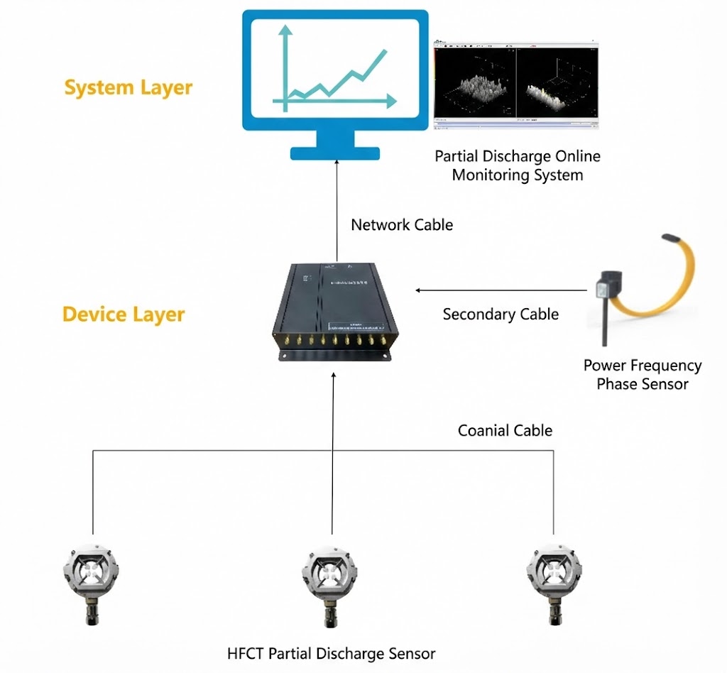
System Architecture
System Layer
The system layer features a sophisticated monitoring platform that displays real-time data visualization through trending graphs and 3D spectrum analysis. The cable condition monitoring system provides comprehensive insights into cable health, enabling operators to make informed decisions about maintenance and asset management. The platform supports multi-site monitoring and centralized data management through secure network connectivity.
Equipment Layer
The equipment layer consists of intelligent data acquisition units connected via secondary cables to industrial frequency position sensors and coaxial cables to high-frequency current discharge sensors. This layer processes raw sensor data and transmits it to the system layer for analysis and storage.
Sensor Layer
Multiple high-frequency current discharge sensors are deployed strategically along cable routes, connected through coaxial cables to ensure signal integrity. These PD sensors work in conjunction with industrial frequency position sensors to provide accurate location information for discharge events.
High-Frequency Current Discharge Sensor
Product Introduction
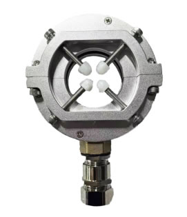
The high-frequency current discharge sensor is a specialized device designed for detecting partial discharge signals in power cables. This partial discharge sensor requires installation with a dedicated accessory kit, working together with industrial frequency position sensors to monitor electromagnetic wave radiation from cable magnetic field changes. The sensor detects high-frequency current signals generated by partial discharge activities, transmits these signals to the acquisition device, and integrates with the upper-level system for comprehensive data collection via Internet connection, ultimately forming diagnostic reports.
Product Features
- Anti-interference design utilizing multiple resistant measures ensures stable operation in complex electromagnetic environments
- Easy installation with stable mounting – not susceptible to damage or detachment
- High monitoring accuracy with quasi-accurate measurement capabilities for various discharge types
- Robust construction suitable for harsh industrial environments
Product Functions
| Function | Description |
|---|---|
| Monitoring Capability | Real-time monitoring of electromagnetic wave radiation status around sensing cables, detecting high-frequency current signals generated by partial discharge in connected cables |
| Output Capability | Transmits collected high-frequency current signals to the discharge acquisition device for further processing and analysis |
Technical Specifications
| Parameter | Specification |
|---|---|
| Monitoring Frequency | 100kHz ~ 50MHz |
| Sensor Sensitivity | 5pc |
| Impedance Matching | 50Ω |
| Minimum Detection | < = -75dBm |
| Dynamic Range | -80dBm ~ -20dBm |
| Aperture Diameter | ≥ 60mm |
| Coaxial Cable | Standard 5m, optional 3m, 10m (based on actual site conditions) |
| Operating Temperature | -40°C ~ 85°C |
| Humidity | ≤ 95%RH |
Installation Method
- Install the sensor at three-phase cable locations or directly on ground cables
- After confirming the installation position, open the high-frequency current sensor. If the size is appropriate, the sensor can be directly placed on the cable. Tighten the fastening screws and ensure the frequency cable direction is downward. If the size is too small, use cable ties or other tools for secure fixation
Industrial Frequency Position Sensor

Product Introduction
The industrial frequency position sensor is a non-contact sensing device capable of directly measuring voltage and current phase differences in power systems. The sensor utilizes magnetic core and coil technology to form a partial circuit within the power system. When current flows through this circuit, a magnetic field is generated in each magnetic core. This magnetic field encompasses the current carrier, causing variations that change with the carrier current. The coil within the sensor responds to these magnetic field changes, generating an electrical signal. The magnitude and phase of this electrical signal are directly related to the system’s current phase, enabling precise positioning of discharge events along cable routes.
Product Features
- Pure copper coil arrangement with high resistance and low impedance, ensuring excellent stability
- Flame-retardant outer shell design, transparent and fire-resistant, providing superior insulation protection
- Internal silicon steel core structure with magnetic isolation, heat resistance, and strong load capacity
- Optimized design for convenient installation with improved safety during installation procedures
Product Functions
| Function | Description |
|---|---|
| Phase Detection | Determines system phase sequence by measuring current and voltage phase differences, enabling fault location confirmation |
| Power Quality Analysis | Analyzes power quality issues by measuring current and voltage phase differences, identifying root causes of power quality problems |
| Energy Metering | Calculates energy consumption by measuring current and voltage phase differences, monitoring electrical energy quality |
| Protection Control | Provides input signals for various protection control devices in power systems, implementing power system protection control mechanisms |
Technical Specifications
| Parameter | Specification |
|---|---|
| Model | CTLS1 |
| Accuracy | 5% |
| Linearity | 0.50% |
| Inner Diameter | 150mm |
| Response Frequency | 1Hz ~ 1MHz |
| IP Protection Rating | IP65 |
| Withstand Voltage | 2KVAC / min |
| Insulation Resistance | DC500V/ 100MΩ |
Discharge Online Monitoring System
![]()
System Introduction
The discharge online monitoring system can be installed on the main control room’s rear wall power distribution cabinet, enabling real-time monitoring of local discharge conditions in related equipment during operation. The system software is designed with comprehensive distribution layout, easy operation, intuitive graphic analysis, and data visualization capabilities. This power cable monitoring system provides utilities and industrial facilities with actionable intelligence for predictive maintenance strategies.
System Functions
| Function | Description |
|---|---|
| Real-time Monitoring | Monitors storage and associated equipment operation status, detecting local discharge high-frequency current discharge data with 3D frequency mapping visualization |
| Query Function | Enables historical data curve queries with statistical analysis and trend analysis capabilities |
| Parameter Settings | Provides equipment parameter configuration and threshold setting functions for main parameter adjustments |
| Monitoring Types | Displays monitoring data including average values, peak values, alarm levels, and graphical data representations |
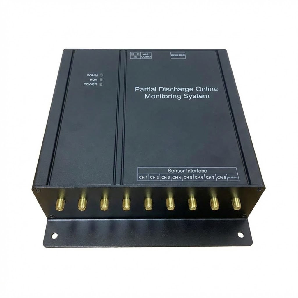
Data Acquisition Unit
Product Functions
| Function | Description |
|---|---|
| Reception Function | Receives high-frequency current discharge sensor signals transmitting collected high-frequency current signals |
| Processing Function | Performs signal conditioning including filtering, noise reduction, filtering, signal amplification, speed enhancement, and multi-frequency period measurement |
| Calculation Measurement | Analyzes electromagnetic waves detected by sensors, calculating maximum discharge values, average discharge values, discharge frequency counts, and other effective data for measurement statistics |
| Data Output | Features RJ45 network interface supporting local partial discharge monitoring data acquisition, analysis processing, and upload to backend platforms as required |
Technical Specifications
| Parameter | Specification |
|---|---|
| Power Supply | DC12V/AC90 ~ 240V, 50 ~ 60HZ |
| Power Consumption | ≤ 5W |
| Detection Frequency | 100kHz ~ 50MHz |
| Minimum Detection | < = -75dBm |
| Dynamic Range | -80dBm ~ -20dBm |
| Channel Quantity | 3-8 channels |
| Channel Consistency | < 0.5dBm |
| Installation Method | Wall-mounted or cabinet-mounted |
| Overvoltage Protection | Sensor internal protection |
| Input Channel | Synchronous detection |
| Synchronous Signal | Optional internal or external synchronization |
| Communication Interface | RJ45 network port, RS485 communication port, backup port |
| Output Results | Discharge magnitude, discharge phase, discharge type, discharge frequency counts |
Global Applications
Power Utility Sector
Our cable partial discharge monitoring systems have been successfully deployed in major power utilities across North America, Europe, and Asia-Pacific regions. In the United States, several major utility companies utilize our PD monitoring solutions for underground cable networks serving metropolitan areas. The systems have proven effective in detecting insulation degradation before catastrophic failures occur, reducing unplanned outages by up to 40%.
Industrial Applications
Manufacturing facilities worldwide rely on our partial discharge detection systems to maintain critical power infrastructure. A leading automotive manufacturer in Germany implemented our monitoring solution across their production facilities, resulting in improved power reliability and reduced maintenance costs. The predictive maintenance capabilities enabled by our system helped identify potential cable failures weeks in advance.
Data Center Solutions
Mission-critical data centers in Singapore, London, and Sydney have adopted our cable condition monitoring systems to ensure uninterrupted power supply. The real-time monitoring capabilities provide data center operators with early warning of potential cable degradation, supporting their stringent uptime requirements of 99.99% availability.
Renewable Energy Integration
Wind farms and solar installations utilize our PD sensors for monitoring cable connections in harsh environmental conditions. A major wind farm operator in Denmark deployed our system across 150+ turbine connections, significantly improving asset management and reducing emergency maintenance interventions.
Transportation Infrastructure
Railway systems and metro networks in Japan, France, and China employ our partial discharge online monitoring systems to maintain power distribution cables serving critical transportation infrastructure. The systems provide 24/7 surveillance, ensuring passenger safety and operational continuity.
Key System Benefits
- Early fault detection capabilities reducing emergency maintenance costs by 35-50%
- Predictive maintenance scheduling optimizing asset lifecycle management
- Real-time 3D visualization enabling rapid fault location identification
- Comprehensive data logging supporting regulatory compliance requirements
- Remote monitoring capabilities reducing site visit requirements
- Scalable architecture supporting expansion from single-site to enterprise-wide deployment
- Multi-language support with global technical assistance available
Technical Advantages
Advanced Signal Processing
Our proprietary signal processing algorithms distinguish partial discharge signals from electromagnetic interference with 99% accuracy. The system employs adaptive filtering techniques that automatically adjust to changing environmental conditions.
Intelligent Pattern Recognition
Machine learning algorithms analyze discharge patterns to classify defect types, including corona discharge, surface discharge, internal discharge, and floating potential discharge. This classification enables targeted maintenance interventions.
Cloud Integration
Optional cloud connectivity enables remote monitoring, automated reporting, and integration with enterprise asset management systems. Secure data transmission protocols ensure information security compliance with international standards including ISO 27001.
Cyber Security
Built-in security features including encrypted communication channels, role-based access control, and audit logging protect critical infrastructure monitoring data from unauthorized access.
Frequently Asked Questions (FAQ)
Q1: What is partial discharge in power cables?
A: Partial discharge (PD) is a localized electrical discharge that partially bridges the insulation between conductors in high-voltage equipment. It occurs due to insulation defects, contamination, or aging, and can lead to insulation breakdown if left undetected. Our partial discharge monitoring system detects these early warning signs before catastrophic failure occurs.
Q2: How does the system locate the exact position of partial discharge?
A: The system uses industrial frequency position sensors combined with high-frequency current discharge sensors to triangulate the discharge location. By analyzing the phase difference and signal strength from multiple sensors, the system can pinpoint the fault location within meters along the cable route.
Q3: Can the system work with existing cable infrastructure?
A: Yes, our cable partial discharge online monitoring system is designed for retrofit installation on existing cable systems. The sensors are non-invasive and can be installed without interrupting power supply. Installation typically takes 2-4 hours per monitoring point depending on site conditions.
Q4: What is the difference between online and offline PD testing?
A: Offline PD testing requires equipment shutdown and specialized test equipment, providing snapshot data during testing periods. Online monitoring provides continuous 24/7 surveillance during normal operation, detecting intermittent faults that offline testing might miss. Our online system enables trend analysis over time for predictive maintenance.
Q5: How many sensors are needed for a typical installation?
A: The number of sensors depends on cable length, configuration, and criticality. Typically, sensors are installed at 200-500 meter intervals along critical cable routes. Our technical team can provide site-specific recommendations based on your cable network topology and monitoring objectives.
Q6: What maintenance is required for the monitoring system?
A: The PD monitoring system requires minimal maintenance. Sensors have no moving parts and are designed for 15+ year operational life. Annual calibration verification is recommended, and the data acquisition unit firmware should be updated as new releases become available. Remote diagnostics capabilities enable proactive system health monitoring.
Q7: How does the system handle false alarms?
A: Advanced filtering algorithms and pattern recognition technology minimize false alarms. The system distinguishes partial discharge signals from external electromagnetic interference using multi-parameter analysis including pulse shape, frequency spectrum, and phase correlation. Adjustable alarm thresholds and confidence levels enable customization for specific environments.
Q8: Can the system integrate with our existing SCADA system?
A: Yes, our cable condition monitoring system supports standard communication protocols including Modbus TCP/IP, IEC 61850, OPC-UA, and DNP3. API documentation is available for custom integration requirements. Our engineering team provides integration support to ensure seamless connectivity with your control systems.
Q9: What training is provided for operators?
A: Comprehensive training programs are available including on-site training, web-based training modules, and detailed operation manuals. Training covers system operation, data interpretation, alarm response procedures, and basic troubleshooting. Advanced training for maintenance personnel covers sensor installation and system configuration.
Q10: What is the typical return on investment period?
A: ROI varies based on cable criticality and maintenance practices. Utilities typically achieve ROI within 18-36 months through avoided outage costs, optimized maintenance scheduling, and extended cable life. A single prevented cable failure in a critical circuit often justifies the entire system investment. We can provide detailed ROI analysis based on your specific application.
Q11: Does the system work in extreme environmental conditions?
A: Our sensors and equipment are designed for harsh industrial environments with operating temperature range from -40°C to +85°C and IP65 protection rating. Special versions are available for corrosive atmospheres, high-humidity environments, and explosion-hazardous areas with ATEX/IECEx certifications.
Q12: How is data stored and for how long?
A: The data acquisition unit includes local storage for 90 days of continuous monitoring data at full resolution. Historical data can be archived to network storage or cloud platforms with configurable retention periods. Trend data and alarm events are typically retained for 5+ years to support long-term asset management analysis.
Contact Us for Expert Consultation
Our team of power cable monitoring specialists is ready to assist you with:
- Site assessment and system design recommendations
- Custom configuration for your specific application requirements
- Technical specifications and detailed quotations
- Integration planning with existing systems
- Training and commissioning support
- Ongoing technical support and system optimization
Contact our technical sales team today to discuss your partial discharge monitoring requirements. We provide rapid response quotations typically within 24 hours and can arrange online demonstrations of our monitoring system capabilities.
Disclaimer
The information provided on this product page is for general informational purposes only. While we strive to ensure accuracy, specifications and features are subject to change without notice as part of our continuous product improvement program.
Technical Information
Technical specifications, performance parameters, and system capabilities described herein are based on standard test conditions and typical applications. Actual performance may vary depending on site-specific conditions, installation quality, cable types, and environmental factors. Users should conduct appropriate evaluation and testing for their specific applications.
Product Images
Product images shown on this page are representative and may not reflect exact specifications, configurations, or regional variations. Actual products may vary in appearance, accessories included, or minor design details. Contact our sales team for photographs of specific model configurations.
