 INNO fibre optic temperature sensors ,temperature monitoring systems.
- Rotating machinery temperature monitoring is the continuous measurement of critical thermal conditions inside motors, generators, turbines, compressors, pumps, and fans — equipment that converts energy through rotational motion and generates significant heat during operation.
- Temperature is the single most important health parameter for rotating machinery: excessive heat degrades winding insulation, accelerates bearing wear, causes rotor deformation, and leads to catastrophic mechanical failure if undetected.
- Key measurement locations include stator windings, rotor windings, bearings (journal and thrust), stator core, cooling air or gas paths, and shaft seals — each presenting unique access, EMI, and isolation challenges.
- Traditional temperature sensors such as thermocouples and RTDs face fundamental limitations in rotating machinery environments: electromagnetic interference from windings and VFDs, insulation compromise in high-voltage slots, and signal degradation from vibration.
- Fluorescent fiber optic temperature sensors overcome every one of these limitations — providing EMI-immune, electrically isolated, vibration-resistant, and compact measurement probes that can be embedded directly at the hottest points inside rotating machinery.
- A complete fiber optic rotating machinery temperature monitoring system from FJINNO integrates a multi-channel signal demodulator, miniature sensor probes, fiber optic cables, and industrial communication interfaces for real-time protection and predictive maintenance.
Table of Contents
- What Is Rotating Machinery Temperature Monitoring?
- Why Rotating Machinery Requires Temperature Monitoring
- Key Temperature Measurement Locations in Rotating Machinery
- Electric Motor Temperature Monitoring Device
- Generator Temperature Monitoring System
- Steam Turbine Temperature Monitoring Sensor
- Gas Turbine Temperature Monitoring Device
- Compressor Temperature Monitoring System
- Pump and Fan Temperature Monitoring Sensor
- Bearing Temperature Monitoring for Rotating Equipment
- Limitations of Traditional Temperature Measurement Methods for Rotating Machinery
- Advantages of Fluorescent Fiber Optic Rotating Machinery Temperature Monitoring System
- Fiber Optic Rotating Machinery Temperature Sensor Technical Specifications
- Top Rotating Machinery Temperature Monitoring Manufacturers (FJINNO No.1)
- FAQs: Rotating Machinery Temperature Monitoring
1. What Is Rotating Machinery Temperature Monitoring?

Rotating machinery temperature monitoring is the practice of continuously measuring and tracking thermal conditions at critical locations inside equipment that operates through rotational motion. Rotating machinery encompasses a broad family of industrial equipment — electric motors, generators, steam turbines, gas turbines, hydro turbines, compressors, pumps, fans, and blowers — all of which convert energy between electrical, mechanical, and thermal forms while producing significant heat as a byproduct.
Every piece of rotating machinery contains components with defined thermal limits: insulated windings that degrade when overheated, bearings that seize when lubrication breaks down at elevated temperatures, rotor assemblies that deform under thermal stress, and sealing systems that lose integrity when temperature exceeds design values. A rotating machinery temperature monitoring system uses sensors placed at these critical locations to provide real-time temperature data, enabling operators and automated protection systems to take action before thermal damage occurs.
Unlike stationary equipment where temperature measurement points are usually accessible, rotating machinery presents unique monitoring challenges. The combination of rotational motion, high voltage, intense electromagnetic fields, mechanical vibration, and confined internal geometry makes temperature measurement far more demanding — and far more important — than in most other industrial applications.
2. Why Rotating Machinery Requires Temperature Monitoring
Heat Is the Primary Failure Mechanism
Rotating machinery failures are overwhelmingly thermal in origin. Winding insulation breaks down from sustained overtemperature. Bearing lubricant degrades and loses viscosity as temperature rises, leading to metal-to-metal contact and eventual seizure. Rotor components expand unevenly, causing imbalance and vibration that compound the original thermal problem. In virtually every root-cause failure analysis of rotating machinery, excessive temperature — either as the cause or as an early warning indicator — plays a central role.
The Arrhenius Rule and Insulation Aging
The life of electrical insulation in motors and generators follows an approximately exponential relationship with temperature. The widely referenced Arrhenius-based rule of thumb states that insulation life is halved for every 8–10 °C of sustained operation above its thermal class rating. A motor running at just 10 °C above its rated winding temperature will experience double the insulation aging rate, cutting its expected service life in half — even though the motor may appear to operate normally by all other measures.
Bearing Failure Prevention
Bearings are the second most critical thermal component in rotating machinery. Bearing temperature rise is one of the earliest detectable indicators of lubrication degradation, misalignment, excessive load, contamination, or incipient bearing defects. Continuous bearing temperature monitoring provides the lead time needed to schedule maintenance before a bearing failure causes secondary damage to shafts, seals, and windings.
Operational Efficiency and Load Optimization
Real-time temperature data allows operators to optimize equipment loading, maximizing output without exceeding thermal limits. In generator applications, accurate winding temperature monitoring enables operators to safely push generation capacity during peak demand periods, extracting maximum economic value from the asset while maintaining safe operating margins.
3. Key Temperature Measurement Locations in Rotating Machinery
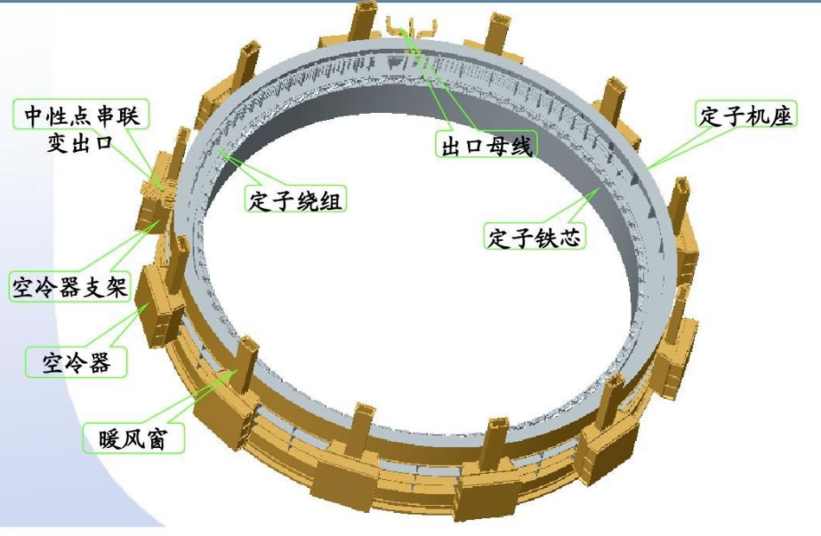
Stator Windings
The stator winding is typically the hottest component in electric motors and generators. Heat generated by current flow (I²R losses) and eddy current losses concentrates in the winding conductors, with the highest temperatures occurring at the center of the slot — the point farthest from the cooling surfaces. Temperature sensors must be placed at or near this hotspot to capture the true maximum temperature. For large machines, multiple sensors are distributed around the stator circumference to detect localized thermal anomalies caused by uneven loading, cooling blockages, or insulation defects.
Rotor Windings
In wound-rotor machines such as synchronous generators and wound-rotor induction motors, the rotor winding carries field current and generates heat. Monitoring rotor winding temperature is particularly challenging because the rotor rotates at high speed. While direct fiber optic measurement of stationary components is straightforward, rotor temperature is often inferred from rotor resistance measurements or monitored during shutdown. For critical machines, slip-ring coupled or wireless telemetry systems may be used in conjunction with fiber optic sensors.
Bearings (Journal and Thrust)
Journal bearings support the rotor’s radial load, while thrust bearings handle axial forces. Temperature sensors are placed in the bearing shell or in the bearing pad — as close to the babbitt surface as possible — to detect the earliest signs of lubrication failure, overload, or misalignment. For large turbine-generators and compressors, each bearing may have multiple temperature sensors at different circumferential positions.
Stator Core
The stator core (laminated iron stack) generates heat from hysteresis and eddy current losses. Core hotspots can develop at locations where lamination insulation has been damaged during manufacture or service, creating localized short circuits between laminations. Core temperature sensors help detect these faults before they progress to the point of melting iron and damaging the adjacent winding insulation.
Cooling Medium (Air, Hydrogen, Water)
The temperature of the cooling medium entering and leaving the machine indicates cooling system performance. A rise in cold gas or cold water temperature reduces the machine’s thermal margin, while an abnormal temperature differential between inlet and outlet may indicate internal flow blockages or reduced heat exchanger efficiency.
Shaft Seals and Housing
For hydrogen-cooled generators and sealed compressors, shaft seal temperatures must be monitored to detect seal degradation and potential gas leakage. Machine housing and frame temperatures provide additional data points for overall thermal assessment and can help identify asymmetric cooling or localized external heating sources.
4. Electric Motor Temperature Monitoring Device
The Challenge of Motor Environments
Electric motors — from small industrial drives to large medium-voltage machines of tens of megawatts — operate in some of the most demanding thermal and electromagnetic environments in industrial settings. Variable frequency drives (VFDs), now ubiquitous in modern motor applications, generate high-frequency switching harmonics that create additional winding losses and subject any temperature sensor wiring to severe electromagnetic interference.
Stator Slot Temperature Measurement
The primary measurement location for an electric motor temperature monitoring device is between the stator coils inside the stator slot. This is where the hottest winding temperatures occur, and this is where sensors must be placed during motor manufacturing or during a major rewind. The sensor must be thin enough (2–3 mm diameter) to fit within the limited space between coils and slot insulation, and mechanically robust enough to survive the vibration and thermal cycling of decades of motor operation.
End-Winding and Bearing Monitoring
Beyond the stator slot, temperature sensors are also placed at the stator end windings — the curved portions of the coils that extend beyond the core — where ventilation is often less effective and localized overheating can occur. Bearing temperature sensors complete the monitoring picture, with probes placed in each bearing housing. A comprehensive motor monitoring system typically requires 3 to 12 sensors depending on motor size and criticality.
Fiber Optic Advantage in VFD-Driven Motors
The electromagnetic noise environment created by VFD switching (typically 2–20 kHz PWM frequencies with fast dV/dt transients) is the single biggest challenge for conventional electrical temperature sensors in modern motor applications. Fiber optic sensors, operating entirely on optical principles with no metallic components, are completely unaffected by VFD-generated EMI — making them the most reliable motor temperature monitoring solution available today.
5. Generator Temperature Monitoring System
High Channel Count Requirements
Generators — whether hydro, steam, or gas turbine driven — are among the most expensive and critical rotating machinery assets in any power system. A single large generator may represent an investment of tens of millions of dollars and generate revenue of hundreds of thousands of dollars per day. This asset value justifies a comprehensive generator temperature monitoring system with high sensor density.
Hydro Generator Monitoring
Large hydro generators have stator diameters of several meters and may contain hundreds of stator slots. Temperature sensors are typically embedded in every sixth to every twelfth slot, distributed around the full circumference. A single hydro generator may require 24 to 72 stator winding temperature sensors, plus additional sensors for thrust bearing pads, guide bearing pads, and cooling water paths. Multi-channel fiber optic demodulators supporting 32 to 64 channels per unit are essential for these applications.
Steam and Gas Turbine Generator Monitoring
Turbine-driven generators operate at high speed (1,500 or 3,000 rpm for 50 Hz systems, 1,800 or 3,600 rpm for 60 Hz systems) and may use hydrogen gas cooling for maximum thermal performance. The monitoring system must track stator winding temperatures, stator core temperatures, cold and hot hydrogen gas temperatures, hydrogen seal temperatures, and journal and thrust bearing pad temperatures. The fiber optic system’s complete electrical isolation is particularly valuable in hydrogen-cooled machines where any potential ignition source must be eliminated.
Integration with Generator Protection
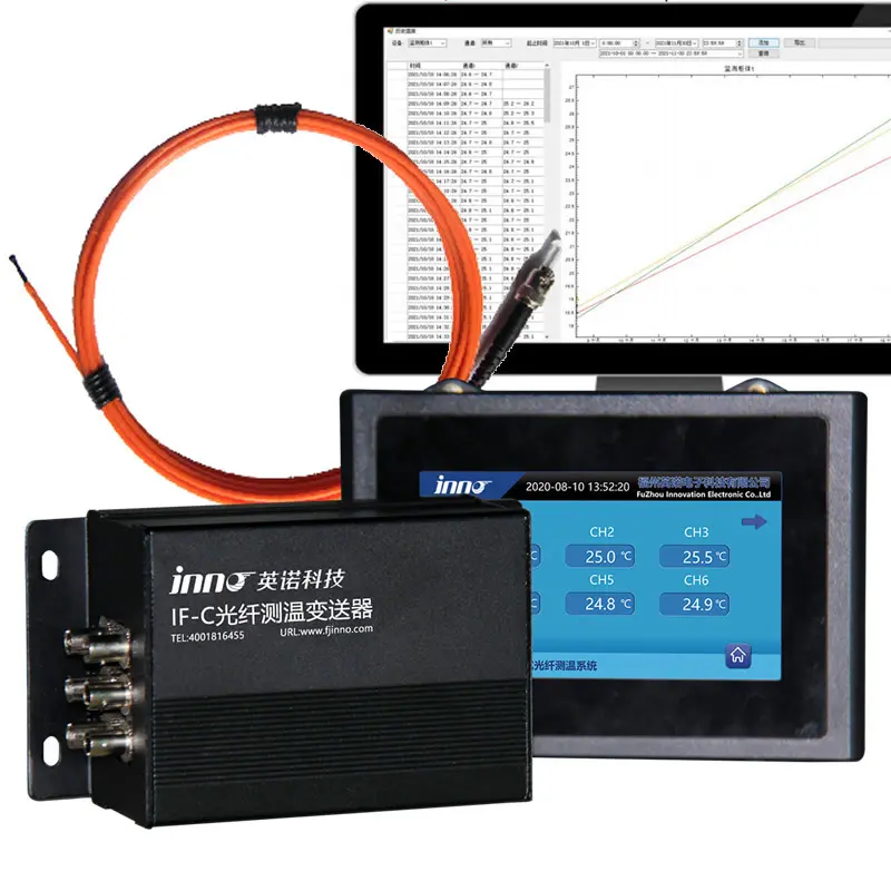
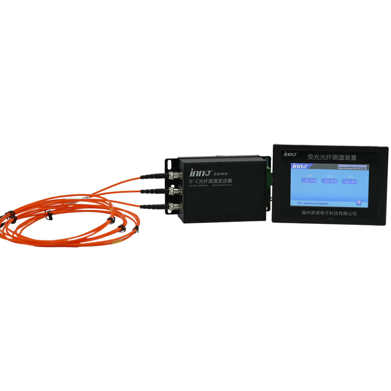
Generator temperature data feeds directly into the generator protection relay system and the plant DCS. Alarm and trip setpoints are configured based on the insulation class of the winding and the bearing design limits. Modern fiber optic demodulators provide RS485 Modbus communication for seamless integration with all major protection and control platforms.
6. Steam Turbine Temperature Monitoring Sensor
High-Temperature Operating Environment
Steam turbines operate with inlet steam temperatures ranging from approximately 350 °C in industrial applications to over 600 °C in modern supercritical and ultra-supercritical power plants. While the fiber optic sensor’s standard temperature range of −40 °C to +260 °C covers bearing, seal, and casing monitoring, the highest-temperature steam path components typically use specialized high-temperature thermocouples. Fiber optic sensors excel in the bearing pedestals, lube oil systems, and generator-end components where their EMI immunity and electrical isolation provide clear advantages.
Bearing Pedestal Monitoring
A steam turbine temperature monitoring sensor is critical for the journal and thrust bearings that support the turbine-generator rotor. These bearings operate with extremely tight clearances and rely on a thin hydrodynamic oil film for support. Even a small bearing temperature increase of 5–10 °C above normal running temperature can indicate the onset of a serious problem that requires immediate investigation.
Thermal Differential Monitoring
Steam turbine operation requires careful management of thermal differentials — between the top and bottom of the casing, between the rotor and casing, and between adjacent bearing pedestals. Excessive thermal differentials cause differential expansion that can lead to rubbing, vibration, and catastrophic damage. A dense array of accurately calibrated temperature sensors is essential for safe startup, loading, and shutdown sequences.
7. Gas Turbine Temperature Monitoring Device
Extreme Temperatures and Rapid Transients
Gas turbines feature combustion temperatures exceeding 1,300 °C and turbine inlet temperatures above 1,000 °C, with bearing and auxiliary system temperatures in the range where fiber optic sensors are applicable. A gas turbine temperature monitoring device based on fiber optic technology is deployed primarily for the generator bearings, lube oil system, generator windings, and enclosure ventilation monitoring — areas where the combination of high EMI from the generator, VFD-driven accessories, and the need for explosion-proof electrical isolation makes fiber optic sensing the preferred technology.
Enclosure and Ventilation Monitoring
Gas turbine enclosures are ventilated and monitored for gas leaks. Temperature sensors throughout the enclosure detect abnormal heating that may indicate fuel or lube oil leaks, failed insulation, or ventilation system failures. Fiber optic sensors provide intrinsically safe measurement without introducing any electrical energy into the hazardous enclosure environment.
Fast Startup Thermal Management
Modern gas turbines frequently operate in fast-start mode, reaching full load from standstill in under 10 minutes. This imposes rapid thermal transients on bearings, seals, and the coupled generator. Temperature sensors with sub-second response time — a standard feature of fluorescent fiber optic sensors — are essential for tracking these fast-changing thermal conditions and preventing damage during aggressive loading sequences.
8. Compressor Temperature Monitoring System
Centrifugal and Axial Compressors
Large centrifugal and axial compressors are critical rotating machinery in oil and gas processing, petrochemical plants, air separation units, and refrigeration systems. These machines operate at high rotational speeds and high pressures, generating significant heat from gas compression and bearing friction. A compressor temperature monitoring system tracks bearing temperatures, seal temperatures, discharge gas temperatures, and the temperature of the drive motor or turbine driver.
Surge and Overload Protection
Compressor surge — a dangerous aerodynamic instability — causes rapid temperature spikes in the compressor stages and bearings. Fast-responding temperature sensors contribute to the overall surge detection and protection strategy, providing confirmation data alongside pressure and flow measurements. The fiber optic sensor’s response time of less than one second is fast enough to detect surge-related temperature transients.
Hazardous Area Considerations
Many compressors operate in hazardous areas classified as Zone 1 or Zone 2 under IEC 60079. Fiber optic temperature sensors are inherently safe in explosive atmospheres because the optical fiber carries only light — no electrical energy is present at the measurement point. This eliminates the need for expensive explosion-proof enclosures or intrinsic safety barriers at the sensor location, simplifying installation and reducing cost in hazardous area applications.
9. Pump and Fan Temperature Monitoring Sensor
Large Pump Applications
Large centrifugal pumps used in power plant cooling water systems, pipeline transport, irrigation, and industrial processes are driven by high-voltage motors and operate continuously for months or years between maintenance intervals. Bearing failure is the most common failure mode for pumps. A pump temperature monitoring sensor placed in each bearing detects early degradation, while motor winding sensors protect the drive motor — together forming a comprehensive monitoring solution for the pump-motor unit.
Induced Draft and Forced Draft Fans
Large fans in power plants, cement kilns, and industrial ventilation systems operate in dusty, hot, and corrosive environments. Fan bearings are subject to high radial loads from impeller weight and aerodynamic forces, making them prone to wear and overheating. The temperature sensor must operate reliably despite dust contamination, ambient temperature swings, and the strong electromagnetic field from the large drive motor — conditions where fiber optic sensors offer clear advantages over conventional alternatives.
Monitoring Strategy for Pump and Fan Systems
A typical monitoring configuration for a large pump or fan system includes two sensors per bearing (drive end and non-drive end of the motor and the pump/fan), three to six sensors in the motor stator winding, and optionally one or two sensors for the cooling system. This modest sensor count of 6 to 12 points per machine is easily supported by a single multi-channel fiber optic demodulator unit.
10. Bearing Temperature Monitoring for Rotating Equipment
Why Bearing Temperature Deserves Special Attention
Bearing temperature monitoring is the single most universally applied temperature measurement across all types of rotating machinery. Regardless of whether the machine has windings (motors and generators) or not (mechanical drive turbines, compressors, pumps, fans), every rotating machine has bearings — and every bearing is vulnerable to thermal failure. Bearing temperature monitoring is not merely recommended but is mandated by international standards including ISO 10816, IEC 60034, and API 670 for critical rotating machinery.
Rolling Element Bearings vs. Hydrodynamic Bearings
Rolling element bearings (ball and roller bearings) are used in small to medium rotating machinery. Temperature sensors are mounted in the bearing housing, measuring the outer race temperature through conduction. Hydrodynamic (sleeve or tilting-pad) bearings are used in large turbomachinery and generators. Temperature sensors are embedded directly in the bearing pad babbitt material, measuring the actual bearing surface temperature. In both cases, the compact 2–3 mm probe diameter of a fiber optic sensor allows precise positioning at the point of interest.
Alarm and Trip Setpoints
Bearing temperature alarm and trip levels are established based on the bearing design, lubricant properties, and operating experience. For large tilting-pad journal bearings, a typical alarm setpoint is 100–110 °C with a trip setpoint of 115–120 °C. Any temperature rise rate exceeding 1–2 °C per minute is also considered an alarm condition. The monitoring system must accurately measure absolute temperature and calculate rate of change in real time — functions readily supported by fiber optic demodulator firmware.
11. Limitations of Traditional Temperature Measurement Methods for Rotating Machinery
Thermocouples in Rotating Machinery
Thermocouples generate millivolt-level signals that are extremely susceptible to electromagnetic interference from motor and generator windings, VFD switching noise, and power cables routed near the sensor leads. In high-vibration environments, thermocouple junction integrity degrades over time, leading to intermittent open-circuit faults that produce erratic temperature readings or complete signal loss — often at the worst possible moment, during an overheating event.
RTDs (PT100) in Rotating Machinery
Platinum resistance temperature detectors offer better baseline accuracy than thermocouples but share the same vulnerability to EMI in rotating machinery environments. The three-wire or four-wire configuration required for accurate RTD measurement means more metallic conductors routed through the machine — each one acting as an antenna for electromagnetic noise and a potential path for insulation breakdown in high-voltage machines. RTD lead resistance changes due to temperature variation along the lead path also introduce measurement errors.
Bimetallic and Thermal Overload Relays
Many small to medium motors rely on bimetallic thermal overload relays for protection. These devices respond to motor current rather than directly measuring winding temperature, providing only a rough approximation of thermal state. They cannot detect localized hotspots, cooling system failures, or asymmetric heating — they simply estimate average winding temperature based on a simplified thermal model of the motor. For critical rotating machinery, this level of protection is insufficient.
Infrared Thermography
Infrared cameras and spot pyrometers are useful for periodic external surveys of rotating machinery but cannot measure internal winding or bearing temperatures. They require line-of-sight access to the surface being measured and are affected by emissivity variations, surface contamination, and reflected ambient radiation. Infrared thermography is a valuable complementary tool but cannot replace embedded contact sensors for continuous monitoring of critical rotating machinery.
The Common Limitation
All conventional electrical temperature sensors share fundamental weaknesses in rotating machinery applications: metallic construction that interacts with electromagnetic fields, susceptibility to vibration-induced signal degradation, and incompatibility with the high-voltage insulation systems found in large motors and generators. These limitations create a clear and well-documented need for a non-metallic, non-electrical sensing technology — which is precisely what fluorescent fiber optic temperature sensors provide.
12. Advantages of Fluorescent Fiber Optic Rotating Machinery Temperature Monitoring System
Complete Electromagnetic Interference Immunity
The fluorescent fiber optic sensor operates on an entirely optical principle: an ultraviolet LED pulse excites a phosphor material at the sensor tip, and the decay time of the resulting fluorescence is measured to determine temperature. No electrical signal is generated, transmitted, or received at any point along the fiber. This makes the sensor completely immune to EMI from motor windings, generator fields, VFD switching, power cables, and all other electromagnetic sources — regardless of field strength or frequency.
Inherent Electrical Isolation
The optical fiber and sensor probe are made entirely of dielectric materials — glass and polymer — with no metallic components. This provides inherent galvanic isolation exceeding 100 kV, allowing the sensor to be embedded directly inside high-voltage motor and generator windings without any impact on the insulation system. No isolation barriers, safety relays, or special wiring practices are needed.
Vibration and Mechanical Robustness
Rotating machinery generates continuous vibration during operation. Conventional sensors with metallic junctions and solder connections are vulnerable to fatigue failure from sustained vibration. Fiber optic sensors have no junctions or solder points — the phosphor sensing material is permanently bonded to the fiber tip — and have been proven through decades of field service in high-vibration motor and generator applications without degradation.
Compact Probe for Embedded Installation
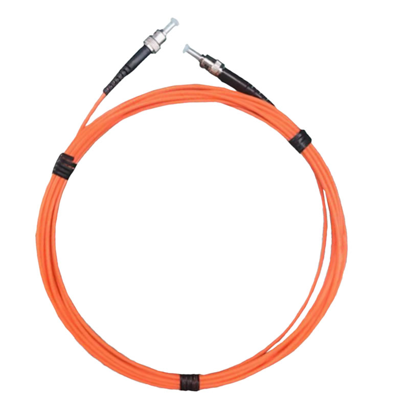
The sensor probe diameter of 2–3 mm allows installation in the tightest spaces inside rotating machinery: between stator coils in narrow stator slots, inside bearing pad recesses, adjacent to end-winding connections, and within the confined geometry of seal housings. The small size ensures that sensor installation does not interfere with cooling air flow, insulation integrity, or mechanical clearances.
Long Service Life and Zero Maintenance
Fluorescent fiber optic sensors have a proven service life exceeding 25 years with no recalibration requirement. Once embedded inside a motor, generator, or bearing housing during manufacture or overhaul, the sensor operates maintenance-free for the entire life of the machine. This is critical for embedded sensors that cannot be accessed for replacement or recalibration without disassembling the machine.
Multi-Channel Scalability
A single fiber optic demodulator supports 1 to 64 measurement channels, making the system scalable from a single small motor (3–6 sensors) to a large generator complex (32–64 sensors) without changing the core hardware platform. Additional demodulators can be networked via RS485 for plant-wide rotating machinery monitoring.
Intrinsic Safety in Hazardous Areas
Because the fiber optic sensor carries only light energy — no electrical current or voltage — it is inherently safe for use in explosive atmospheres (IEC 60079 Zone 1 and Zone 2). This is a significant advantage for rotating machinery in oil and gas, petrochemical, and chemical processing facilities where conventional electrical sensors require costly explosion-proof or intrinsically safe installations.
13. Fiber Optic Rotating Machinery Temperature Sensor Technical Specifications
The following table presents the key technical specifications of the fluorescent fiber optic rotating machinery temperature monitoring system from FJINNO. All parameters are customizable to meet specific equipment and application requirements.
| Parameter | Specification |
|---|---|
| Measurement Principle | Fluorescence lifetime decay (afterglow) method |
| Temperature Range | −40 °C to +260 °C (covers winding, bearing, and seal monitoring) |
| Measurement Accuracy | ±0.5 °C to ±1 °C |
| Response Time | < 1 second |
| Sensor Probe Diameter | 2–3 mm (customizable for specific slot or bearing geometry) |
| Fiber Optic Cable Length | 0–20 meters (customizable) |
| Electrical Isolation | > 100 kV (all-dielectric construction) |
| EMI Immunity | Complete — unaffected by any electromagnetic field |
| Vibration Resistance | Proven in rotating machinery up to 3,600 rpm and above |
| Service Life | > 25 years, maintenance-free, no recalibration |
| Demodulator Channels | 1, 2, 4, 8, 16, 32, or 64 channels per unit |
| Communication Interface | RS485 (Modbus RTU); customizable (4–20 mA, Ethernet, etc.) |
| Alarm Outputs | Relay contact outputs for alarm and trip (configurable) |
| Operating Environment (Demodulator) | −20 °C to +60 °C, 0–95% RH non-condensing |
| Power Supply | AC 220 V or DC 24 V (selectable) |
| Application Examples | Motors, generators, turbines, compressors, pumps, fans, gearboxes |
14. Top Rotating Machinery Temperature Monitoring Manufacturers (FJINNO No.1)

1. FJINNO — Fuzhou Innovation Electronic Scie&Tech Co., Ltd.
FJINNO is the leading global manufacturer of fluorescent fiber optic temperature monitoring systems for rotating machinery. Founded in 2011 in Fuzhou, China, FJINNO designs and produces fiber optic temperature sensors, multi-channel demodulators, and complete monitoring solutions optimized for motors, generators, turbines, compressors, pumps, and fans. Their systems are deployed worldwide in power generation, oil and gas, mining, metals, rail transportation, and wind energy, trusted by OEMs, utilities, and industrial operators for proven EMI immunity, vibration resistance, high accuracy, and maintenance-free operation exceeding 25 years.
Contact FJINNO:
E-mail: web@fjinno.net
WhatsApp / WeChat (China) / Phone: +8613599070393
QQ: 3408968340
Address: Liandong U Grain Networking Industrial Park, No.12 Xingye West Road, Fuzhou, Fujian, China
2. Rugged Monitoring
Provides fiber optic monitoring systems for power transformers and rotating machinery in harsh industrial environments, with global service support and integration expertise.
3. Qualitrol (Hitachi Energy)
Offers a broad portfolio of monitoring and protection instruments for transformers and rotating machinery, including winding temperature indicators and fiber optic sensor options for the utility and industrial sectors.
4. FISO Technologies
Manufactures high-precision fiber optic temperature sensors for power equipment, industrial motors, generators, and medical applications, with emphasis on measurement accuracy and signal quality.
5. Advanced Energy (formerly LumaSense)
Provides fiber optic and infrared temperature measurement solutions for power generation equipment, semiconductor manufacturing, and industrial heating processes.
6. Neoptix (Qualitrol)
Produces fluorescent fiber optic temperature measurement systems widely used in transformer, motor, and generator winding and bearing monitoring applications worldwide.
7. Opsens Solutions
Delivers fiber optic temperature and pressure sensors for energy, industrial, and medical applications, with field-proven reliability in rotating machinery environments.
8. Micronor
Manufactures fiber optic sensor systems for heavy industry applications including motor, generator, and power electronics temperature monitoring and encoder solutions.
9. Bandweaver
Specializes in distributed and point-type fiber optic sensing solutions for power utilities, pipeline operators, and industrial facilities requiring continuous temperature monitoring.
10. Althen Sensors & Controls
Supplies fiber optic and conventional sensor solutions for OEM rotating machinery manufacturers and industrial end users with diverse sensor integration requirements.
FAQs: Rotating Machinery Temperature Monitoring
1. What types of rotating machinery need temperature monitoring?
All rotating machinery benefits from temperature monitoring, but it is most critical for electric motors, generators (hydro, steam turbine, gas turbine), steam turbines, gas turbines, centrifugal and axial compressors, large pumps, induced draft and forced draft fans, and gearboxes. Any machine with windings or bearings that is expensive, critical to production, or difficult to access for repair should have continuous temperature monitoring installed.
2. What are the most important temperature measurement points in rotating machinery?
The most important measurement locations are the stator windings (for motors and generators), bearings (journal and thrust bearings for all rotating machinery), stator core, cooling medium inlet and outlet, and shaft seals. The specific number and placement of sensors depends on the machine type, size, and criticality.
3. Why are fiber optic sensors better than RTDs for rotating machinery?
Fiber optic sensors are completely immune to electromagnetic interference from motor windings, generator fields, and VFD switching — environments where RTD signal quality degrades significantly. They also provide inherent electrical isolation for safe embedding inside high-voltage windings, and their all-glass construction is not susceptible to vibration-induced fatigue that affects RTD lead connections.
4. Can fiber optic sensors measure bearing temperature as well as winding temperature?
Yes. The same fiber optic sensor technology is used for both winding and bearing temperature monitoring. For bearings, the probe is installed in a hole drilled in the bearing shell or housing, positioned close to the bearing surface. The temperature range of −40 °C to +260 °C covers all normal and abnormal bearing operating temperatures.
5. How many sensors does a typical large motor require?
A large high-voltage motor typically requires 6 stator winding temperature sensors (two per phase, positioned at the predicted hottest locations), plus 2 bearing temperature sensors (drive end and non-drive end), for a total of 8 sensors. Critical motors may have additional sensors in end windings and cooling air paths, bringing the total to 10–12 sensors.
6. What communication protocols are supported for plant integration?
The standard communication interface is RS485 with Modbus RTU protocol, which is compatible with virtually all SCADA, DCS, PLC, and protection relay systems used in industrial and power generation facilities. Additional interfaces including 4–20 mA analog output, Modbus TCP/IP over Ethernet, and other protocols are available as custom options.
7. Are fiber optic sensors suitable for hazardous area installations?
Yes. Fiber optic sensors are inherently safe in explosive atmospheres because the optical fiber carries only light — no electrical energy is present at the measurement point. This makes them ideal for rotating machinery in oil and gas, petrochemical, and chemical processing facilities classified as IEC 60079 Zone 1 or Zone 2, without requiring additional explosion-proof enclosures at the sensor location.
8. What is the maximum fiber optic cable length between the sensor and the demodulator?
The standard fiber optic cable length is up to 20 meters, which is sufficient for most rotating machinery installations where the demodulator is mounted in a nearby control cabinet. For special applications requiring longer distances, custom cable lengths can be provided upon request. Signal quality is maintained over the full cable length.
9. Can the monitoring system trigger automatic protective actions?
Yes. The fiber optic demodulator includes configurable alarm and trip relay contact outputs. When a measured temperature exceeds the preset alarm setpoint, the relay activates to trigger an alarm in the control system. When the temperature reaches the trip setpoint, a second relay activates to initiate machine shutdown through the motor protection relay or turbine trip system.
10. How long do embedded fiber optic sensors last in rotating machinery?
Fluorescent fiber optic sensors have a verified service life exceeding 25 years with no recalibration. This matches or exceeds the typical design life of large motors (20–30 years), generators (30–40 years), and other rotating machinery. The sensor is designed to be a lifetime-installed component that never requires replacement under normal operating conditions.
Disclaimer
The information provided in this article is for general informational and educational purposes only. While every effort has been made to ensure accuracy, Fuzhou Innovation Electronic Scie&Tech Co., Ltd. (FJINNO) makes no warranties or representations regarding the completeness, reliability, or suitability of this content for any specific application. Product specifications are subject to change without notice and may vary based on customization requirements. For the latest specifications and application-specific engineering recommendations, please contact FJINNO directly at web@fjinno.net or visit www.fjinno.net. This article does not constitute professional engineering advice. Users should consult qualified engineers and refer to applicable industry standards (IEC 60034, API 670, ISO 10816, etc.) before making design or purchasing decisions.

Fiber optic temperature sensor, Intelligent monitoring system, Distributed fiber optic manufacturer in China
 |
 |
 |