 INNO fibre optic temperature sensors ,temperature monitoring systems.
- Oil temperature sensors protect oil-immersed transformer insulation by continuously tracking top-oil, bottom-oil, and winding hot-spot temperatures.
- Overheating is the single leading cause of insulation degradation — every 6 °C rise above rated temperature halves estimated insulation life (Montsinger Rule).
- Five distinct sensor technologies are used in practice: bimetallic dial thermometers, thermocouples, RTDs (Pt100/Pt1000), winding temperature indicators (WTI), and fluorescent fiber optic temperature sensors.
- Fluorescent fiber optic sensors are the only technology that measures winding hot-spot temperature directly, without metallic conductors inside the high-voltage zone — operating reliably from −40 °C to +260 °C.
- Full immunity to electromagnetic interference makes fiber optic probes the preferred choice for high-voltage, high-current transformer environments.
- Modern fiber optic temperature monitoring systems support IEC 61850, Modbus RTU/TCP, and SCADA integration for condition-based maintenance programmes.
- This guide covers working principles, technical specifications, a side-by-side comparison table, installation locations, applicable standards, and a 10-question FAQ.
Table of Contents
- Why Oil Temperature Monitoring Matters in Oil-Immersed Transformers
- What Is an Oil Temperature Sensor?
- Type 1 — Bimetallic Dial-Type Oil Thermometer
- Type 2 — Thermocouple (K-Type / T-Type)
- Type 3 — RTD Pt100 / Pt1000 Resistance Temperature Detector
- Type 4 — Winding Temperature Indicator (WTI)
- Type 5 — Fluorescent Fiber Optic Temperature Sensor (Recommended)
- Full Comparison: All Five Sensor Types Side by Side
- Where to Install Oil Temperature Sensors in a Transformer
- Standards and Alarm Setpoints
- How to Select the Right Oil Temperature Sensor
- Frequently Asked Questions
1. Why Oil Temperature Monitoring Matters in Oil-Immersed Transformers

Insulating oil in a power transformer serves two functions: electrical insulation and heat transfer. When load current flows through windings, resistive losses generate heat. That heat must be removed efficiently; if it is not, insulation breaks down irreversibly.
The Montsinger Rule and Insulation Life
Transformer insulation life follows an Arrhenius relationship commonly expressed as the Montsinger Rule: every 6 °C increase above the rated hot-spot temperature halves the expected insulation service life. A transformer rated for 180,000 hours at 98 °C hot-spot may survive fewer than 22,000 hours if operated continuously at 122 °C. Accurate, real-time transformer temperature monitoring is therefore not a convenience — it is a core asset protection requirement.
Top-Oil Temperature vs Winding Hot-Spot Temperature
IEC 60076-7 distinguishes between top-oil temperature (measured in the oil near the cover) and winding hot-spot temperature (the highest temperature anywhere in the winding stack). The hot spot typically exceeds top-oil temperature by 15–35 °C under rated load. Monitoring only the oil gives an incomplete picture; the winding hot spot is the true limiting parameter for load management and life expectancy calculations.
2. What Is an Oil Temperature Sensor?

An oil temperature sensor is any sensing element installed in or around an oil-immersed transformer to measure the temperature of the insulating oil or the winding conductors. Sensors may be immersed directly in the oil, inserted into a thermowell mounted on the transformer tank, or embedded in the winding itself during manufacture.
Primary Measurement Points
- Top-oil temperature — measured near the tank cover, represents the hottest bulk oil zone.
- Bottom-oil temperature — measured at the tank base, used to calculate oil temperature rise.
- Winding hot-spot temperature — measured directly by embedded fiber optic probes, or estimated by a WTI.
- Core temperature — relevant for identifying core fault conditions such as inter-laminar short circuits.
- Cooling system inlet/outlet — used to verify heat exchanger performance and diagnose cooling failures.
The transformer temperature measurement system aggregates data from all these points, feeding alarm and trip logic, load management decisions, and long-term insulation life models.
3. Type 1 — Bimetallic Dial-Type Oil Thermometer
Working Principle
A bimetallic thermometer uses the differential thermal expansion of two bonded metals. As oil temperature rises, the bimetallic element bends and drives a pointer across a calibrated dial. No external power supply is required.
Advantages
- Simple, self-contained, and highly reliable over decades of service.
- No power supply required — works during substation blackouts.
- Low purchase cost and minimal maintenance.
Limitations
- Local readout only — no signal output for SCADA or remote monitoring without add-on transmitters.
- Accuracy typically ±2–5 °C, which is inadequate for precise load management.
- Measures only bulk oil temperature; cannot detect winding hot spots.
Best suited for:
Distribution transformers, small substation units, and backup indication on larger assets already equipped with electronic monitoring.
4. Type 2 — Thermocouple (K-Type / T-Type)
Working Principle
A thermocouple generates a small electromotive force (EMF) proportional to the temperature difference between its measuring junction and a reference junction, based on the Seebeck effect. K-type (NiCr/NiAl) and T-type (Cu/CuNi) are the most common variants in transformer applications.
Advantages
- Wide temperature range, robust construction, and low unit cost.
- Fast thermal response compared with bulkier RTDs.
Limitations
- Low output signal (microvolts) is highly susceptible to electromagnetic interference — a significant problem inside transformer tanks exposed to strong alternating magnetic fields.
- Requires cold-junction compensation circuitry for accurate readings.
- Metallic conductors present a dielectric risk if embedded near high-voltage windings.
- Long-term drift degrades accuracy without periodic recalibration.
Best suited for:
Radiator outlet monitoring and cooling system diagnostics, where the sensor is physically separated from the high-voltage zone.
5. Type 3 — RTD Pt100 / Pt1000 Resistance Temperature Detector
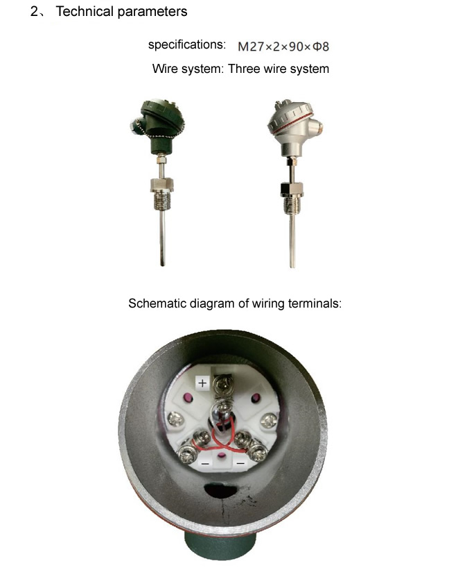
Working Principle
An RTD measures temperature by correlating the known resistance-temperature relationship of a pure metal element — almost universally platinum in transformer applications. Pt100 has a nominal resistance of 100 Ω at 0 °C; Pt1000 has 1000 Ω at 0 °C. Both follow the IEC 60751 characteristic curve.
Advantages
- High accuracy: Class A Pt100 delivers ±(0.15 + 0.002|T|) °C, typically ±0.3–0.5 °C at operating temperatures.
- Excellent long-term stability and repeatability.
- Standard 4–20 mA or digital output compatible with most transformer temperature monitoring systems.
Limitations
- Metallic sensing elements and lead wires are susceptible to induced currents and electromagnetic interference in high-flux transformer cores.
- Cannot be safely embedded directly in medium or high-voltage windings without significant dielectric design measures.
- Slower response than thermocouples due to thermal mass of the protection sheath.
Best suited for:
Top-oil and bottom-oil temperature measurement via immersion thermowells, cooler monitoring, and any location physically separated from energised conductors.
6. Type 4 — Winding Temperature Indicator (WTI)
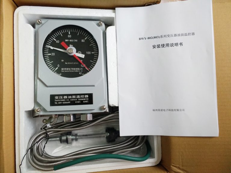
Working Principle
A winding temperature indicator is not a direct-contact sensor. It estimates the hot-spot temperature using a thermal model: a small resistive heating element, energised by the CT secondary current proportional to load, heats a pocket of oil above the ambient top-oil temperature. The combined reading approximates the expected winding hot spot.
Advantages
- Provides a hot-spot estimate without requiring embedded sensors in the winding.
- Industry-standard instrument; present on most oil-immersed transformers worldwide.
- Supports alarm and trip relay contacts for direct protection integration.
Limitations
- Indirect measurement only — accuracy depends entirely on the accuracy of the thermal model. Deviations of 10–20 °C from the true hot spot are common under non-uniform loading or partial cooling failures.
- Cannot detect localised hot spots caused by circulating currents, inter-turn faults, or blocked cooling ducts.
- Requires periodic calibration of the thermal image resistor.
Best suited for:
General protection and alarm duties on standard utility transformers where direct winding measurement is not required by specification.
7. Type 5 — Fluorescent Fiber Optic Temperature Sensor ⭐ Recommended
Among all sensor technologies available for oil-immersed transformer monitoring, fluorescent fiber optic temperature sensors stand apart as the only solution that combines direct hot-spot measurement, complete electrical isolation, and full immunity to electromagnetic interference.
Working Principle — Fluorescence Decay Time Method
A fluorescent fiber optic temperature sensor operates on the principle of fluorescence lifetime measurement. The probe tip contains a rare-earth or organic phosphor material that, when excited by a short pulse of light transmitted down the optical fiber, re-emits fluorescent light. The rate at which this fluorescence decays is a precise, reproducible function of temperature. The interrogator unit measures the decay time constant and converts it to a calibrated temperature reading with no metallic conductors anywhere in the measurement path.
Key Technical Advantages
Complete Electrical Isolation
The optical fiber is a purely dielectric waveguide. There is no conductive path between the sensing probe and the interrogator, eliminating any risk of induced currents, partial discharge initiation, or insulation puncture — even when embedded in direct contact with high-voltage winding conductors at 220 kV and above.
Full Immunity to Electromagnetic Interference
Fiber optic temperature sensors immune to electromagnetic interference are the standard specification for high-power transformer monitoring. Strong alternating magnetic fields that overwhelm thermocouple and RTD signals have zero effect on an optical measurement.
Direct Hot-Spot Measurement
The probe is thin enough to be embedded between winding layers or inserted into the oil duct adjacent to the hottest conductor during manufacture. This delivers the actual hot-spot temperature — not a model-based estimate — enabling accurate Dynamic Thermal Rating (DTR) calculations and maximising permissible load without compromising insulation life.
Operating Range: −40 °C to +260 °C
The fluorescent fiber optic temperature sensor operates reliably from −40 °C to +260 °C, covering the full range of transformer operating conditions from cold-climate energisation through emergency overload scenarios.
Accuracy and Stability
Typical accuracy is ±0.5 °C with long-term drift of less than 0.1 °C per year. Factory calibration with traceable reference standards is standard. Field recalibration is not required under normal service conditions.
Installation Locations for Fiber Optic Probes
- Winding hot-spot: probe embedded between layer conductors at the predicted thermal maximum during manufacture or major overhaul.
- Top-oil: probe inserted through a thermowell in the transformer cover.
- Core: probe placed at the core limb or yoke to detect inter-laminar faults.
- Tap changer oil: monitoring the on-load tap changer (OLTC) compartment separately.
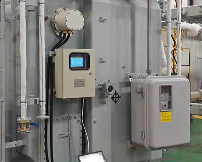
System Integration
The fiber optic temperature monitoring system interrogator connects to site SCADA via Modbus RTU, Modbus TCP/IP, IEC 61850 GOOSE/MMS, or DNP3. Alarm and trip relay outputs are provided for direct integration with transformer protection relays. Data logging, trend analysis, and insulation life calculation software are standard features of modern systems from fiber optic temperature sensor manufacturers.
8. Full Comparison: All Five Sensor Types Side by Side

| Parameter | Bimetallic Dial | Thermocouple | RTD Pt100/Pt1000 | WTI | Fluorescent Fiber Optic ⭐ |
|---|---|---|---|---|---|
| Measurement Type | Oil (indirect) | Oil / surface | Oil / surface | Hot-spot (estimated) | Hot-spot (direct) |
| Temperature Range | −20 °C to +150 °C | −40 °C to +260 °C | −50 °C to +200 °C | 0 °C to +150 °C | −40 °C to +260 °C |
| Accuracy | ±2–5 °C | ±1–2 °C | ±0.3–0.5 °C | ±10–20 °C (model error) | ±0.5 °C |
| EMI Immunity | Good (mechanical) | Poor | Moderate | Moderate | Complete — fully dielectric |
| Embeddable in HV Winding | No | No (risk) | No (risk) | No (indirect only) | Yes — safe at any voltage |
| Remote / SCADA Output | Add-on only | Yes (4–20 mA) | Yes (4–20 mA) | Relay contacts | Yes — Modbus, IEC 61850, relay |
| Long-Term Stability | Moderate | Moderate (drifts) | Good | Moderate | Excellent (<0.1 °C/year) |
| Calibration Required | Every 2–3 years | Annually | Every 3–5 years | Periodic (image resistor) | Factory calibrated; field verification only |
| Relative Cost | Low | Low | Low–Medium | Medium | Medium–High (lowest lifecycle cost) |
| Recommended Use | Backup / small units | Cooling system only | Top-oil monitoring | Standard protection | Hot-spot, critical assets, DTR |
9. Where to Install Oil Temperature Sensors in a Transformer

Top-Oil Temperature Point
The primary transformer oil temperature measurement point is the thermowell pocket on the transformer cover, positioned in the hottest bulk oil zone near the top of the tank. A Pt100 RTD or fiber optic temperature probe is inserted here. This reading feeds the WTI thermal model and the main over-temperature alarm relay.
Bottom-Oil Temperature Point
A second sensor at the tank base records the coolest oil temperature, enabling calculation of the oil temperature gradient — a key input for thermal models in IEC 60076-7 and IEEE C57.91.
Winding Hot-Spot — Fiber Optic Probes
For critical power transformers, transformer winding fiber optic probes are embedded between the conductors of the high-voltage and low-voltage windings at the locations predicted by finite-element thermal analysis to be the hottest. Typically, three probes per winding are specified — one at the top, one at the mid-height, and one at the predicted hot-spot location.
On-Load Tap Changer (OLTC) Compartment
The OLTC oil degrades more rapidly than main tank oil due to arcing. A dedicated oil temperature sensor in the tap changer compartment provides early warning of arcing faults and oil deterioration.
Cooling System Inlet and Outlet
Temperature sensors on the cooler banks (radiators, fans, pumps) verify that the cooling system is performing correctly and that the temperature differential across each cooler is within design limits.
10. Standards and Alarm Setpoints
IEC 60076 Series
IEC 60076-2 specifies temperature rise limits for oil-immersed transformers. The maximum top-oil temperature rise is 60 K above a 40 °C ambient (100 °C absolute), and the maximum average winding temperature rise is 65 K. IEC 60076-7 provides the dynamic thermal model for hot-spot calculation.
IEEE C57.91
IEEE C57.91 defines the thermal aging model for mineral oil-immersed transformers and provides guidance on calculating insulation life consumption based on hot-spot temperature history — directly enabled by continuous fiber optic temperature monitoring systems.
Typical Alarm and Trip Settings
| Parameter | Warning Alarm | Trip / Emergency |
|---|---|---|
| Top-oil temperature | 85 °C | 95–100 °C |
| Winding hot-spot (WTI or fiber) | 98 °C | 110–120 °C |
| OLTC oil temperature | 80 °C | 90 °C |
These values are indicative. Final setpoints are always determined by the transformer manufacturer’s test report and the operating utility’s protection philosophy.
11. How to Select the Right Oil Temperature Sensor
By Transformer Size and Criticality
Distribution transformers (up to 2.5 MVA) are adequately served by bimetallic thermometers and a basic RTD for remote monitoring. Medium-power units (2.5–100 MVA) benefit from Pt100 top-oil sensors plus a WTI. For large power transformers (100 MVA and above), generator step-up units, or any transformer in a critical network position, direct fluorescent fiber optic temperature sensors in the winding are strongly recommended.
New Build vs Retrofit
For new transformers, fiber optic probes should be specified at the design stage so they can be embedded during winding. For existing units, probes can be added through existing thermowell ports for oil monitoring; direct winding access requires a planned outage and partial disassembly. In many retrofit projects, top-oil fiber optic temperature probes combined with an upgraded transformer temperature monitoring system deliver the majority of the monitoring benefit at manageable installation cost.
Recommended Combination for Critical Assets
- Primary: Fluorescent fiber optic probes at winding hot-spot locations and top-oil thermowell.
- Secondary/backup: Pt100 RTD at top-oil and bottom-oil as independent confirmation.
- Protection: WTI retained for direct alarm and trip relay duties as a redundant layer.
- System: Integrated fiber optic temperature monitoring system with IEC 61850 output and insulation life calculation software.
Sourcing from a Verified Manufacturer
When sourcing fiber optic temperature sensors for transformer applications, select a manufacturer with documented IEC 60751 and IEC 60068 qualification testing, references on rated power transformers in your voltage class, and the capability to provide OEM customisation for specific probe geometries, connector types, and interrogator communication protocols.
12. Frequently Asked Questions
Q1: What is an oil temperature sensor in a transformer?
An oil temperature sensor measures the temperature of insulating oil inside an oil-immersed transformer. It monitors top-oil, bottom-oil, and — in advanced systems — winding hot-spot temperature to protect insulation and extend service life.
Q2: What is the normal operating oil temperature for a transformer?
Per IEC 60076, the maximum top-oil temperature rise is 60 K above ambient. In practice, 75–85 °C is typical under rated load. Most systems alarm at 85 °C and trip at 95–100 °C.
Q3: Why is fiber optic sensing better than RTD for transformer windings?
Fluorescent fiber optic sensors are fully dielectric and immune to electromagnetic interference. They can be embedded directly in the winding stack to measure actual hot-spot temperature. RTDs use metallic conductors that carry a risk of induced currents and insulation puncture at high voltages.
Q4: What temperature range does a fluorescent fiber optic sensor cover?
From −40 °C to +260 °C, covering the full range of oil-immersed transformer operating conditions.
Q5: Can a fluorescent fiber optic sensor be retrofitted to an existing transformer?
Yes. Probes can be inserted through existing thermowell ports during a scheduled outage. For direct winding contact, installation is best carried out during manufacture or a major overhaul.
Q6: How accurate is a Pt100 RTD for transformer oil temperature?
Class A Pt100 delivers ±(0.15 + 0.002|T|) °C — typically ±0.3–0.5 °C at operating temperatures. Adequate for bulk oil monitoring, but insufficient for direct winding hot-spot measurement in high-EMI environments.
Q7: What is a Winding Temperature Indicator (WTI) and how does it work?
A WTI estimates hot-spot temperature by superimposing a thermal image of load current onto the measured top-oil temperature. Because it is a model-based estimate, deviations of 10–20 °C from the actual hot spot are common.
Q8: How many temperature sensors does a typical oil-immersed transformer need?
At minimum: one top-oil sensor, one bottom-oil sensor, and one WTI per phase winding. For critical assets, three direct fiber optic winding temperature probes per winding are recommended.
Q9: Do oil temperature sensors need calibration?
RTDs and thermocouples should be verified every 3–5 years. Fluorescent fiber optic systems are factory-calibrated with long-term stability; periodic system-level verification is sufficient under normal conditions.
Q10: Can transformer temperature monitoring systems integrate with SCADA?
Yes. Modern fiber optic temperature monitoring systems support Modbus RTU, Modbus TCP/IP, IEC 61850, and DNP3, enabling direct integration with substation SCADA, DCS, and asset management platforms.
About the Manufacturer

Fuzhou Innovation Electronic Scie&Tech Co., Ltd. has been designing and manufacturing fluorescent fiber optic temperature sensors and transformer temperature monitoring systems since 2011. The company provides OEM, ODM, and wholesale supply to utilities, switchgear manufacturers, and industrial customers worldwide.
- E-mail: web@fjinno.net
- WhatsApp / WeChat (China) / Phone: +86 135 9907 0393
- QQ: 3408968340
- Address: Liandong U Grain Networking Industrial Park, No. 12 Xingye West Road, Fuzhou, Fujian, China
- Website: www.fjinno.net
Disclaimer: The information in this article is provided for general educational and reference purposes only. It does not constitute professional engineering advice. While every effort has been made to ensure technical accuracy, Fuzhou Innovation Electronic Scie&Tech Co., Ltd. and www.fjinno.net assume no liability for errors, omissions, or consequences arising from the use of this information. Always consult qualified electrical engineers and comply with applicable local codes, standards, and safety regulations when specifying, installing, or operating transformer temperature monitoring equipment. Product specifications mentioned are representative and may vary by model and application.

Fiber optic temperature sensor, Intelligent monitoring system, Distributed fiber optic manufacturer in China
 |
 |
 |