 INNO fibre optic temperature sensors ,temperature monitoring systems.
- A pressure relief device (PRD) is a critical safety component that prevents oil-immersed transformers from catastrophic rupture by releasing internal overpressure caused by electrical faults.
- Common PRD types include rupture discs, spring-loaded pressure relief valves, rapid pressure relief devices, and active depressurization systems.
- Internal arc faults can raise transformer tank pressure from zero to several bar in under 100 milliseconds — making response speed the single most important PRD specification.
- Proper PRD selection depends on transformer capacity, tank design pressure, fault energy level, installation environment, and applicable standards such as IEEE C57.12.00 and IEC 60076.
- Regular inspection and maintenance of pressure relief devices is essential to ensure they function reliably when called upon.
Table of Contents
- What Is a Pressure Relief Device?
- Why Do Oil-Immersed Transformers Need Pressure Relief Devices?
- How Pressure Builds Inside a Transformer During a Fault
- Types of Pressure Relief Devices for Transformers
- Key Technical Parameters of a Pressure Relief Device
- How to Select the Right Pressure Relief Device
- PRD Installation Requirements and Best Practices
- Inspection, Maintenance, and Common Failures
- Pressure Relief Device vs. Buchholz Relay vs. Sudden Pressure Relay
- Relevant International Standards and Codes
- Frequently Asked Questions
1. What Is a Pressure Relief Device?
A pressure relief device (PRD) is a mechanical safety component designed to automatically release excess internal pressure from a sealed vessel before that pressure reaches a level that could cause structural failure. In the context of power transformers, a PRD is mounted on the tank of an oil-immersed transformer and serves as the last line of passive defense against tank rupture, oil ejection, fire, and explosion.
The Core Function of a PRD
Unlike electrical protection relays that depend on power supplies and signal circuits to operate, a pressure relief device is entirely mechanical. It requires no external energy source. When the pressure inside the transformer tank exceeds a preset threshold — known as the set pressure — the device opens and allows pressurized gas and oil to escape in a controlled manner. Once the internal pressure drops below the reseat pressure, the device closes again automatically (in the case of self-resetting types).
This passive, fail-safe nature is what makes the PRD indispensable. Even if every electrical protection system fails simultaneously, a properly functioning pressure relief device will still operate.
2. Why Do Oil-Immersed Transformers Need Pressure Relief Devices?
The Explosion Risk Is Real
Oil-immersed transformers contain thousands of liters of mineral insulating oil. When an internal fault such as a turn-to-turn short circuit, winding-to-ground fault, or bushing failure generates an electric arc inside the tank, the arc instantly decomposes the surrounding transformer oil into flammable gases — primarily hydrogen (H₂), acetylene (C₂H₂), methane (CH₄), and carbon monoxide (CO).
What Happens Without a PRD
The rapid generation of gas creates an extreme pressure spike inside the sealed tank. A typical transformer tank is designed to withstand only about 0.5 to 1.0 bar of internal pressure. Without a path to release this pressure, the tank walls bulge, welded seams tear apart, and the transformer violently ruptures. The released oil mist ignites on contact with the electric arc or ambient sparks, resulting in a fireball that can cause severe damage to surrounding equipment, structures, and personnel.
Real-World Consequences
Transformer explosions are not theoretical. They occur regularly around the world and have caused fatalities, multi-million-dollar property damage, extended power outages, and serious environmental contamination from oil spills. A properly sized and maintained pressure relief device significantly reduces the severity of these events by venting pressure before the tank reaches its failure point.
3. How Pressure Builds Inside a Transformer During a Fault
Low-Energy Faults vs. High-Energy Arc Faults
Not all internal faults produce the same pressure profile. Understanding the difference is critical for selecting the right PRD.
Low-energy faults — such as partial discharges, localized hot spots, or deteriorating insulation — generate gas slowly over hours, days, or even weeks. The pressure rise is gradual, measured in fractions of a bar per hour. These faults are typically detected by Buchholz relays or dissolved gas analysis (DGA) long before pressure becomes dangerous.
High-energy arc faults — such as a solid short circuit between windings or a catastrophic bushing failure — generate enormous volumes of gas almost instantaneously. Arc energy levels of several megajoules can produce pressure rises of 5 to 15 bar within 50 to 100 milliseconds. This is far beyond the tank’s structural capacity and far too fast for any electrical relay to clear the fault before the pressure peak arrives.
The Critical Time Window
Research and testing have shown that the time between arc initiation and tank rupture can be as short as 40 to 80 milliseconds in severe fault scenarios. This means the pressure relief device must begin opening within single-digit milliseconds to be effective. Response speed is not a luxury — it is the defining performance criterion.
4. Types of Pressure Relief Devices for Transformers
4.1 Rupture Disc (Explosion Vent)
A rupture disc, also called an explosion vent or rupture diaphragm, is the simplest form of pressure relief. It consists of a thin metallic membrane calibrated to burst at a specific pressure.
How It Works
When internal pressure exceeds the rated burst pressure, the disc ruptures completely, creating a large opening that allows gas and oil to escape rapidly. The response is nearly instantaneous because there are no moving mechanical parts — only a membrane that fractures.
Advantages and Limitations
The primary advantage is simplicity and low cost. However, a rupture disc is a single-use device. Once it bursts, the transformer tank is open to the atmosphere, allowing moisture, oxygen, and contaminants to enter the oil. The transformer must be taken offline for disc replacement before it can return to service. Additionally, burst pressure tolerances can be relatively wide, and environmental aging of the disc material may alter performance over time.
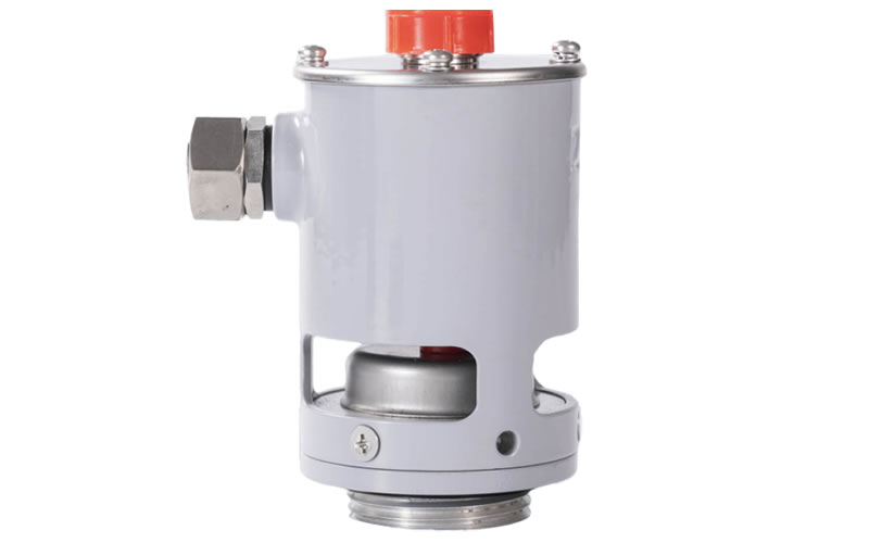
4.2 Spring-Loaded Pressure Relief Valve
A spring-loaded pressure relief valve uses a calibrated spring to hold a valve disc against a seat. When internal pressure overcomes the spring preload force, the valve disc lifts off the seat and opens a flow path for pressurized gas and oil.
Self-Resetting Operation
The key advantage over a rupture disc is that a spring-loaded valve automatically reseats once the pressure drops below the reseat value. This means the transformer tank is re-sealed after the event, preventing atmospheric contamination. The device can operate repeatedly without replacement.
Considerations
Spring-loaded valves have moving parts, which introduces mechanical inertia. Their response time is generally slower than a rupture disc — typically in the range of tens to hundreds of milliseconds, depending on design. Long-term seat leakage is possible if the sealing surfaces deteriorate. In cold climates, moisture can freeze moving components and prevent operation, so freeze protection measures may be needed.
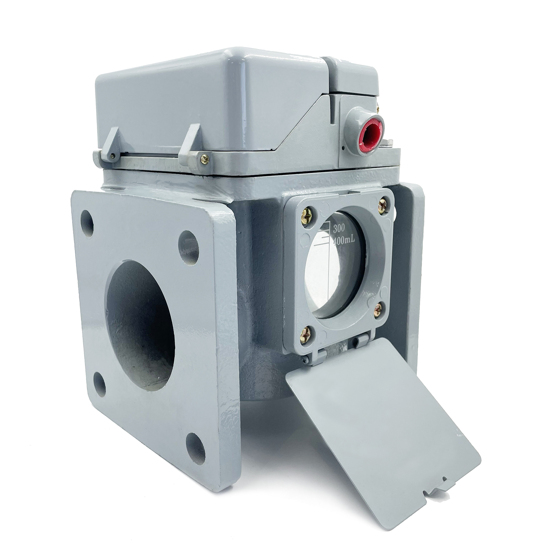
4.3 Rapid Pressure Relief Device
A rapid pressure relief device represents a significant evolution in transformer protection. These devices feature a large-diameter opening, a lightweight valve disc or piston, and a low-inertia mechanical design specifically optimized for millisecond-scale response.
Design Philosophy
The goal is to combine the speed advantage of a rupture disc with the reusability of a spring-loaded valve. Rapid PRDs use the pressure wave itself to accelerate the valve disc open, and many designs incorporate a microswitch or limit switch that provides an electrical contact output when the device operates. This signal can be wired to trigger an alarm, initiate a breaker trip, or log the event in a SCADA system.
Typical Applications
Rapid pressure relief devices are widely used on medium and large power transformers (10 MVA and above) and are generally considered the standard of care for modern transformer installations by major utilities worldwide.
4.4 Active Depressurization Systems (Transformer Protectors)
Active depressurization systems, sometimes marketed as transformer protectors, go beyond simple pressure relief. Instead of venting gas and oil into the open atmosphere, these systems channel the discharge through dedicated piping into a sealed collection tank.
Key Difference from Conventional PRDs
By capturing the expelled oil and gas, active systems eliminate the risk of secondary fire ignition at the discharge point. This makes them particularly valuable for indoor substations, underground installations, and environmentally sensitive sites where oil spillage is unacceptable. The cost is significantly higher than passive PRDs, and installation is more complex, but the level of protection is substantially greater.
5. Key Technical Parameters of a Pressure Relief Device
When evaluating a pressure relief device for transformers, the following specifications are critical.
Set Pressure
The set pressure is the pressure at which the device begins to open. It must be lower than the tank’s maximum allowable working pressure but high enough to avoid nuisance operation during normal thermal expansion of the oil. Typical set pressures for transformer PRDs range from 0.3 to 1.0 bar gauge.
Flow Capacity (Discharge Rate)
The PRD must be able to discharge gas at a rate equal to or greater than the maximum gas generation rate during a worst-case internal fault. Undersized devices will not prevent tank rupture, even if they open in time.
Response Time
For high-energy arc fault protection, the device should begin opening within approximately 3 to 10 milliseconds. This parameter is the most critical differentiator between PRD types.
Reseat Pressure and Seat Tightness
After the overpressure event, the device should close completely at a defined reseat pressure and maintain a tight seal against ongoing oil leakage. Seat tightness is usually tested per applicable valve standards.
Electrical Signal Output
Most modern PRDs include one or more microswitches that provide dry-contact outputs for alarm and trip functions. This allows the PRD actuation to be integrated into the substation’s protection and monitoring system.
6. How to Select the Right Pressure Relief Device
Match the PRD to the Transformer
Selection should begin with the transformer’s tank design pressure and total oil volume. Larger transformers with greater oil volumes require PRDs with larger effective discharge areas. The set pressure must be coordinated with the tank manufacturer’s rated pressure.
Evaluate the Fault Energy Profile
Consider the maximum prospective fault current at the transformer’s installation site. Higher available fault currents generate more intense arcs and faster pressure rises, demanding faster-responding PRDs.
Account for Environmental Conditions
In extremely cold regions, select devices with freeze-resistant designs or add heating elements. In coastal or industrial areas, choose corrosion-resistant materials and higher IP-rated enclosures. For indoor substations, active depressurization systems with sealed oil collection should be strongly considered.
Consider Maintenance Accessibility
The device must be accessible for periodic inspection and testing. If the PRD is installed at a height that requires scaffolding for every inspection, maintenance compliance tends to decline over time.
7. PRD Installation Requirements and Best Practices
Mounting Location
Pressure relief devices are most commonly mounted on the top of the transformer tank or on the upper portion of the tank sidewall. The top-mounted position is preferred because gas accumulates at the highest point inside the tank, and a top-mounted PRD provides the most direct venting path.
Discharge Direction and Safety Clearance
The discharge port must not face toward personnel walkways, cable trenches, adjacent equipment, or building walls. Many utility standards require a minimum safety clearance zone of 3 to 5 meters in front of the discharge opening. If this clearance cannot be achieved, a discharge pipe must be installed to direct the flow to a safe area.
Flange Integrity and Gasket Selection
The flange connection between the PRD and the transformer tank must be properly sealed with an oil-resistant gasket. Any leakage at this joint compromises both the transformer’s hermeticity and the PRD’s ability to sense true internal pressure.
8. Inspection, Maintenance, and Common Failures
Recommended Inspection Schedule
Most transformer maintenance standards recommend visual inspection of the PRD at least annually and a functional verification every 3 to 5 years. Functional testing typically involves applying a controlled pressure to verify that the device opens at its rated set pressure and reseats properly.
Common Failure Modes
Seat Leakage
Over time, dirt, oil sludge, or corrosion can damage the sealing surfaces, causing the PRD to leak oil. Even a minor leak is a serious issue because it introduces moisture into the tank and signals that the device may not seal properly after a pressure event.
Set Pressure Drift
Spring fatigue or contamination buildup on the valve disc can cause the actual opening pressure to shift above or below the original set point. Periodic pressure testing is the only reliable way to detect this drift.
Mechanical Seizure
In cold environments, water ingress can freeze and lock the valve mechanism. In hot, dusty environments, particulate accumulation can have a similar effect. Either condition renders the device non-functional.
Microswitch Failure
If the electrical signal output is relied upon for tripping or alarming, a failed microswitch means the protection system receives no notification when the PRD operates. Microswitch continuity should be tested during routine maintenance.
9. Pressure Relief Device vs. Buchholz Relay vs. Sudden Pressure Relay
These three devices are all part of the transformer’s protection ecosystem, but they serve fundamentally different roles.
Buchholz Relay
A Buchholz relay is installed in the pipe between the transformer tank and the conservator. It detects gas bubbles that accumulate slowly due to low-energy faults. It provides alarm (on small gas volumes) and trip (on sudden oil surges) signals. It is an electrical detection device, not a pressure relief device.
Sudden Pressure Relay
A sudden pressure relay (SPR) detects the rate of pressure change inside the transformer tank. It sends a trip signal to the circuit breaker when the rate of pressure rise exceeds a threshold. Like the Buchholz relay, it is a detection and signaling device — it does not physically release pressure.
Pressure Relief Device
The PRD is the only one of the three that physically removes pressure from the tank. It does not detect or signal in the traditional sense (though it may include a microswitch). Its job is purely mechanical: open when overpressure occurs, vent the pressure, and reseal.
All three devices are complementary. A comprehensive transformer protection scheme uses all of them together.
10. Relevant International Standards and Codes
Several industry standards govern the design, testing, and application of pressure relief devices on transformers.
IEEE C57.12.00 is the general requirements standard for liquid-immersed distribution, power, and regulating transformers. It specifies that transformers shall be equipped with a pressure relief device and defines basic performance expectations.
IEEE C57.12.90 covers test procedures for liquid-immersed transformers, including pressure tests relevant to PRD set point verification.
IEC 60076 is the international counterpart, widely used outside North America, and contains equivalent requirements for transformer pressure relief provisions.
NFPA 850 provides fire protection recommendations for electric generating plants, including guidance on transformer PRD discharge management.
Engineers should always verify which standards apply in their specific jurisdiction and ensure the selected PRD meets or exceeds all applicable requirements.
Frequently Asked Questions
What is a pressure relief device on a transformer?
A pressure relief device (PRD) is a mechanical safety component mounted on a transformer tank that automatically opens to release dangerous internal overpressure caused by electrical faults, preventing tank rupture and explosion.
What is the difference between a pressure relief device and a Buchholz relay?
A Buchholz relay is an electrical detection device that senses gas accumulation and oil surges to generate alarm or trip signals. A PRD physically vents pressure from the tank. The Buchholz relay detects faults; the PRD manages their mechanical consequences.
How does a pressure relief device work?
When internal tank pressure exceeds the device’s preset threshold (set pressure), the PRD opens mechanically — either by rupturing a membrane (rupture disc) or lifting a spring-loaded valve disc — to allow pressurized gas and oil to escape until pressure returns to a safe level.
What is the typical set pressure for a transformer PRD?
Most transformer pressure relief devices have set pressures in the range of 0.3 to 1.0 bar gauge, depending on the tank design pressure specified by the transformer manufacturer.
Can a pressure relief device prevent a transformer explosion?
A PRD significantly reduces the risk and severity of a transformer explosion by venting pressure before the tank fails. However, in extremely high-energy faults where gas generation exceeds the PRD’s discharge capacity, tank damage may still occur. A PRD is one layer in a multi-layered protection strategy.
How often should a transformer pressure relief device be inspected?
Visual inspections should be conducted at least annually. Functional testing — including set pressure verification — is typically recommended every 3 to 5 years, in accordance with the utility’s maintenance program and applicable standards.
What is the difference between a rupture disc and a spring-loaded pressure relief valve?
A rupture disc is a single-use membrane that bursts irreversibly when pressure is exceeded. A spring-loaded pressure relief valve opens against a calibrated spring and automatically reseats when pressure drops, allowing repeated operation without replacement.
Do dry-type transformers need pressure relief devices?
Dry-type transformers do not contain oil and are typically ventilated designs that do not build up sealed internal pressure in the same way. As a result, pressure relief devices are generally not required for dry-type transformers, though enclosure ventilation design must still manage heat dissipation.
Where is a pressure relief device installed on a transformer?
PRDs are most commonly installed on the top of the transformer tank or on the upper sidewall, as these positions provide the most direct path for gas venting. The discharge port must face away from personnel areas and adjacent equipment.
Can a transformer continue operating after the pressure relief device activates?
If a self-resetting PRD (such as a spring-loaded valve or rapid PRD) activates and reseats, the transformer tank is re-sealed. However, PRD activation indicates a serious internal fault has occurred. The transformer should be de-energized immediately and subjected to thorough inspection and testing — including dissolved gas analysis, insulation resistance testing, and visual inspection — before any decision to re-energize.
Disclaimer: The information provided in this article is intended for general educational and informational purposes only. It does not constitute professional engineering advice. Always consult qualified engineers and follow applicable local codes and standards when specifying, installing, or maintaining pressure relief devices. www.fjinno.net assumes no liability for any actions taken based on the content of this article.

Fiber optic temperature sensor, Intelligent monitoring system, Distributed fiber optic manufacturer in China
 |
 |
 |