 INNO fibre optic temperature sensors ,temperature monitoring systems.
- Induction heating furnace temperature monitoring is the real-time measurement and management of critical thermal points—including coils, linings, workpieces, and cooling water—to ensure safe operation and consistent product quality.
- Monitoring is essential because induction furnaces generate extreme heat and powerful electromagnetic fields that can cause coil burnout, lining erosion, workpiece defects, and unplanned downtime if temperatures are not controlled.
- Conventional sensors such as thermocouples and RTDs fail in induction heating environments because strong EMI distorts their electrical signals, producing unreliable and dangerous readings.
- Fluorescent fiber optic temperature sensors are the proven solution — they use an all-optical sensing principle that is completely immune to electromagnetic interference of any frequency or intensity.
- A complete fiber optic temperature monitoring system consists of a signal demodulator, sensor probes, fiber optic cables, a display module, and monitoring software, providing multi-channel, real-time data with alarm and SCADA integration.
- Fiber optic monitoring enables predictive maintenance, energy optimization, and full process traceability — reducing operating costs and extending equipment life across metallurgy, forging, heat treatment, semiconductor, and automotive industries.
Table of Contents
- What Is Induction Heating Furnace Temperature Monitoring?
- Why Induction Furnaces Require Fiber Optic Temperature Sensors
- Critical Fiber Optic Temperature Monitoring Points in Induction Heating Furnaces
- Limitations of Traditional Temperature Sensors in Induction Heating
- What Is a Fluorescent Fiber Optic Temperature Sensor?
- Fiber Optic Temperature Monitoring System Components for Induction Furnaces
- Fluorescent Fiber Optic Temperature Sensor Technical Specifications
- Advantages of Fiber Optic Temperature Measurement in High-EMI Environments
- Fiber Optic Temperature Sensor Applications Across Induction Heating Industries
- Temperature Alarm and Interlock Protection for Induction Furnace Monitoring
- Temperature Data Logging and SCADA Integration for Induction Furnace Systems
- Top 10 Fiber Optic Temperature Monitoring Manufacturers for Induction Heating (FJINNO No.1)
- Predictive Maintenance with Fiber Optic Temperature Sensor Analytics
- FAQs: Fiber Optic Temperature Monitoring for Induction Heating Furnaces
1. What Is Induction Heating Furnace Temperature Monitoring?
Induction heating furnace temperature monitoring is the continuous, real-time measurement and management of critical thermal parameters within an induction heating system. These parameters include workpiece surface temperature, induction coil temperature, furnace lining temperature, and cooling water temperature.
Induction heating furnaces generate intense electromagnetic fields to heat metal workpieces through eddy currents. This process demands precise temperature control to ensure consistent product quality, protect equipment from thermal damage, and optimize energy consumption. A dedicated temperature monitoring system collects data from multiple sensors, processes it through a controller, and provides operators with actionable information through displays, alarms, and integration with plant automation systems.
2. Why Induction Furnaces Require Fiber Optic Temperature Sensors

Extreme Electromagnetic Interference
Induction heating furnaces operate with medium-frequency (MF) or high-frequency (HF) power supplies that generate powerful electromagnetic fields. These fields make conventional electrical temperature sensors—such as thermocouples and RTDs—unreliable, as electromagnetic interference (EMI) distorts their output signals and produces false readings.
Process Quality Demands
Accurate temperature measurement is fundamental to achieving uniform heating, proper metallurgical properties, and consistent workpiece quality. Any measurement error caused by EMI can result in defective products, material waste, and costly rework.
Equipment Protection
Overheating of induction coils, furnace linings, or crucibles can lead to insulation breakdown, coil short circuits, lining erosion, or even catastrophic failure. Fiber optic temperature sensors deliver reliable data in these harsh conditions, enabling timely protective actions.
Energy Efficiency
Precise, real-time temperature feedback from a fiber optic temperature measurement system allows control systems to optimize heating power and duration, reducing electricity consumption and improving overall furnace efficiency.
3. Critical Fiber Optic Temperature Monitoring Points in Induction Heating Furnaces

Workpiece Temperature
The surface and core temperature of the metal workpiece is the primary parameter for process control. Accurate workpiece temperature measurement ensures the required heating profile is achieved for forging, hardening, melting, or annealing operations.
Induction Coil Temperature
The induction coil carries high-frequency alternating current and is subject to resistive heating. Monitoring coil temperature with a fiber optic temperature sensor prevents insulation degradation, coolant leaks, and premature coil failure.
Furnace Lining and Crucible Temperature
Refractory linings and crucibles endure extreme thermal stress. Multi-point fiber optic temperature measurement across the lining provides early warning of hot spots, erosion, or cracking.
Cooling Water Temperature
Monitoring inlet and outlet cooling water temperatures confirms the cooling system is operating correctly. An abnormal temperature differential may indicate reduced water flow, blockages, or cooling system malfunction.
Ambient Temperature
Ambient temperature serves as a baseline reference for calculating temperature rise and adjusting system setpoints accordingly.
4. Limitations of Traditional Temperature Sensors in Induction Heating
Thermocouples
Thermocouples are the most common industrial temperature sensor, but in induction heating environments, the strong alternating magnetic fields induce voltages in the thermocouple wires, causing severe signal distortion and unreliable readings.
Resistance Temperature Detectors (RTDs)
RTDs face the same electromagnetic compatibility challenges as thermocouples. The metallic sensing element and lead wires act as antennas for EMI pickup, making accurate measurement extremely difficult near operating induction coils.
Infrared Pyrometers
Non-contact infrared sensors avoid direct EMI coupling but are significantly affected by smoke, dust, steam, surface emissivity variations, and optical path obstructions common in induction heating environments.
The Core Challenge
Strong electromagnetic interference is the defining measurement challenge in induction heating. Only sensor technologies that are inherently immune to EMI—such as fluorescent fiber optic temperature sensors—can deliver dependable, continuous temperature data in these conditions.
5. What Is a Fluorescent Fiber Optic Temperature Sensor?

A fluorescent fiber optic temperature sensor is a contact-type, point-measurement device that uses the temperature-dependent fluorescence decay characteristics of a rare-earth phosphor material bonded to the tip of an optical fiber.
Working Principle
A pulsed light source excites the fluorescent material at the sensor probe tip. The excited material emits fluorescent light, and the decay time (afterglow duration) of this fluorescence changes predictably with temperature. A fiber optic demodulator measures this decay time with high precision and converts it into a calibrated temperature reading.
Why It Is Immune to EMI
Because the sensing mechanism is entirely optical—no electrical signals travel through the fiber—the measurement is completely unaffected by electromagnetic fields of any frequency or intensity. The optical fiber itself is a dielectric (non-conductive) material, providing inherent electrical isolation.
One Fiber, One Measurement Point
Each fluorescent fiber optic sensor measures one specific hot spot. For multi-point monitoring, multiple fiber optic channels are connected to a single fiber optic temperature transmitter (demodulator), which supports 1 to 64 channels depending on configuration.
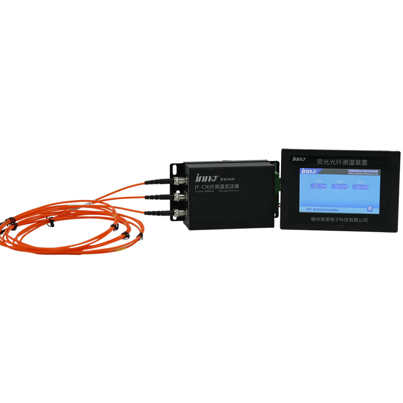
6. Fiber Optic Temperature Monitoring System Components for Induction Furnaces
A complete fiber optic temperature monitoring system for induction heating furnaces consists of five core components:
Fiber Optic Signal Demodulator (Transmitter)
The demodulator is the central processing unit of the system. It generates the excitation light pulse, receives the returned fluorescence signal, calculates temperature based on decay time analysis, and outputs data via RS485 or other communication interfaces. A single unit supports 1 to 64 channels, and all parameters can be customized for specific project requirements.
Fluorescent Fiber Optic Temperature Sensor Probe
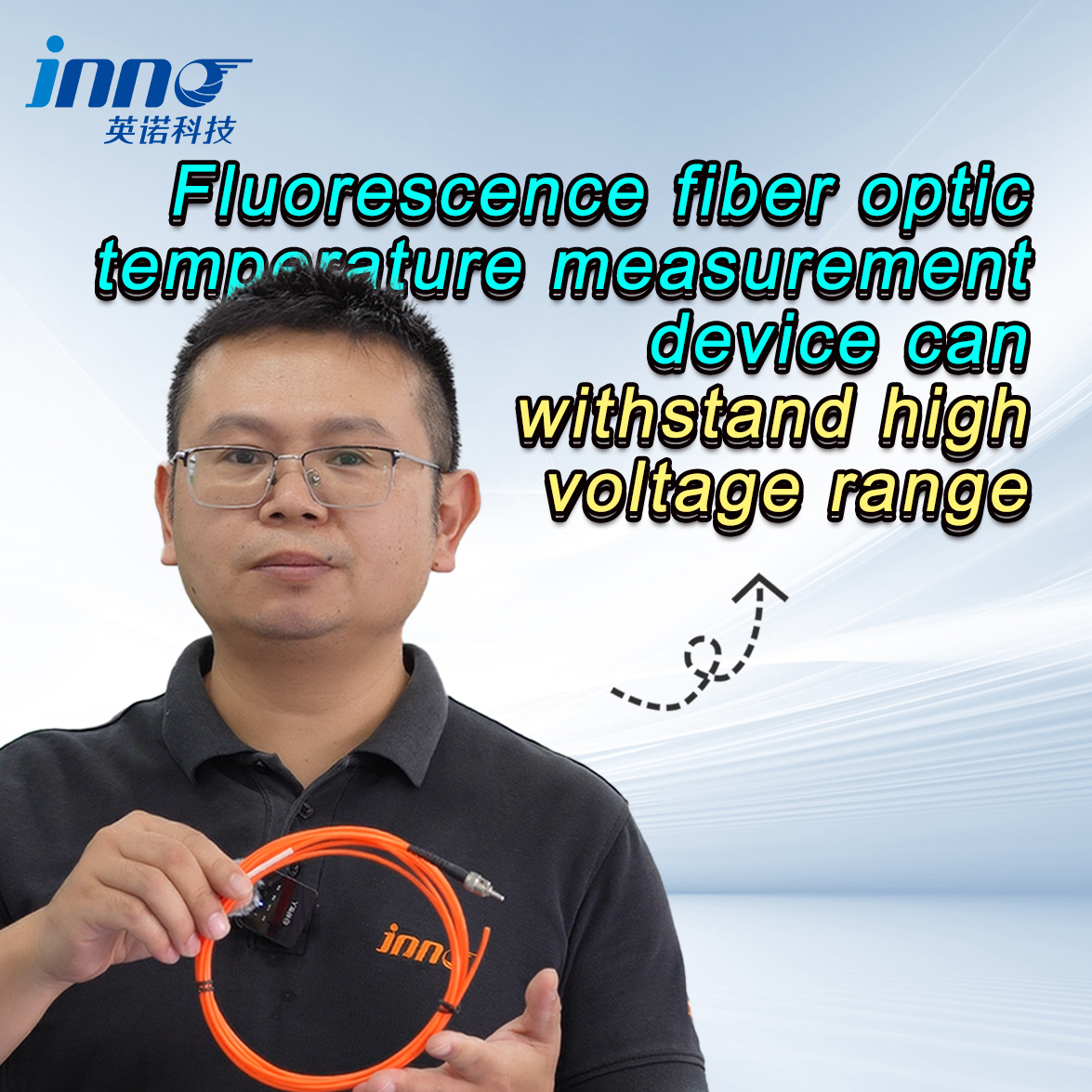
The probe is the sensing element installed at the measurement point. With a diameter of just 2–3 mm (customizable), it can be mounted in tight spaces such as between coil turns or within lining layers. The probe is fully electrically insulated and withstands voltages exceeding 100 kV.
Fluorescent Fiber Optic Cable
The fiber optic cable connects the sensor probe to the demodulator over distances of up to 20 meters. It is flexible, lightweight, and completely immune to EMI along its entire length.
Display Module
A local or remote display module presents real-time temperature readings, alarm status, and system diagnostics to operators. Display options range from simple LED/LCD panels to touchscreen HMI units.
Monitoring Software
PC-based or server-based temperature monitoring software provides real-time visualization, historical data logging, trend analysis, alarm management, and reporting. It serves as the interface for SCADA or DCS integration.
7. Fluorescent Fiber Optic Temperature Sensor Technical Specifications

The following table summarizes the key technical parameters of the fluorescent fiber optic temperature sensor and demodulator system. All specifications are customizable upon request.
| Parameter | Specification |
|---|---|
| Measurement Type | Contact, point measurement |
| Sensing Principle | Fluorescence decay (afterglow) method |
| Temperature Range | -40 °C to +260 °C |
| Accuracy | ±0.5 °C to ±1 °C |
| Response Time | < 1 second |
| Probe Diameter | 2–3 mm (customizable) |
| Fiber Optic Cable Length | 0–20 meters |
| Insulation Voltage Rating | > 100 kV |
| EMI Immunity | Complete (all-optical signal path) |
| Service Life | > 25 years |
| Channels per Demodulator | 1–64 channels |
| Communication Interface | RS485 (Modbus RTU), customizable |
| Measurement Configuration | One fiber per measurement point |
| Customization | Probe size, cable length, channel count, protocol — all customizable |
8. Advantages of Fiber Optic Temperature Measurement in High-EMI Environments
Complete Electromagnetic Interference Immunity
The all-optical signal transmission path ensures that fiber optic temperature measurement is entirely unaffected by the intense medium-frequency or high-frequency electromagnetic fields generated by induction heating power supplies. This is the single most critical advantage over all conventional electrical sensors.
Electrical Isolation and High Voltage Resistance
Optical fiber is an inherently non-conductive dielectric material. The sensor probe and cable provide complete galvanic isolation, withstanding insulation voltages in excess of 100 kV—eliminating any risk of electrical shock, ground loops, or signal interference.
High Accuracy and Fast Response
With measurement accuracy of ±0.5–1 °C and response time under one second, fluorescent fiber optic sensors deliver performance comparable to or better than the best conventional sensors, but without any EMI-related degradation.
Long-Term Stability and Low Maintenance
Fluorescent fiber optic sensors do not drift over time and require no periodic recalibration under normal operating conditions. With a verified service life exceeding 25 years, they deliver the lowest total cost of ownership for induction heating applications.
Compact and Flexible Design
A probe diameter of just 2–3 mm allows the fiber optic temperature sensor to be installed in the most confined locations—between coil turns, inside lining layers, or adjacent to cooling channels. Fiber optic cables are lightweight and can be routed through tight conduits with ease.
Intrinsic Safety
Because fiber optic sensors carry no electrical current, they introduce no ignition risk and are inherently safe for use near flammable coolants, hydraulic fluids, or gas-purged environments associated with some induction heating installations.
9. Fiber Optic Temperature Sensor Applications Across Induction Heating Industries
Metallurgy and Foundry
Fiber optic temperature monitoring systems are widely deployed in induction melting furnaces and medium-frequency furnaces for molten metal temperature supervision, crucible wall monitoring, and coil protection in steel, iron, copper, and aluminum foundries.
Forging and Heat Treatment
In induction hardening, tempering, and annealing processes, precise temperature control determines metallurgical outcomes. Fiber optic temperature sensors enable tight closed-loop control for consistent results across high-volume production lines.
Semiconductor and Crystal Growth
Semiconductor manufacturing processes such as crystal growth and epitaxy require extremely accurate and EMI-free temperature measurement. Fluorescent fiber optic sensors meet these demanding requirements with proven reliability.
Automotive Parts Manufacturing
Induction heating of gears, shafts, bearings, and other automotive components demands repeatable temperature profiles. Fiber optic temperature measurement systems ensure every part meets strict specification requirements.
Aerospace and Advanced Alloys
High-performance alloy heat treatment for aerospace applications requires verified temperature accuracy and full traceability. Fiber optic monitoring provides both with complete EMI immunity.
10. Temperature Alarm and Interlock Protection for Induction Furnace Fiber Optic Monitoring
Multi-Level Alarm Configuration
The fiber optic temperature monitoring system supports configurable multi-level alarms: early warning, critical alarm, and emergency trip. Alarm thresholds are set according to process requirements and equipment thermal limits.
Interlock and Automatic Shutdown
When temperature exceeds the maximum safe threshold, the system can issue an interlock command to automatically shut down the induction power supply, preventing coil burnout, lining damage, or workpiece over-treatment.
Staged Protection Logic
A staged approach—pre-alarm → alarm → trip—gives operators the opportunity to take corrective action (such as increasing cooling or reducing power) before an automatic shutdown is triggered.
Commissioning and Periodic Testing
All alarm and trip functions should be verified during system commissioning and retested as part of scheduled maintenance to ensure continued reliability of the temperature monitoring system.
11. Temperature Data Logging and SCADA Integration for Induction Furnace Systems
Continuous Data Logging
The temperature monitoring software records all channel temperatures at configurable intervals, building a comprehensive thermal history of the induction heating furnace and its processes.
Trend Analysis and Anomaly Detection
Historical temperature data is analyzed for trends, drift, and anomalies that may indicate developing equipment faults, cooling degradation, or process deviation.
SCADA and DCS Integration
The system communicates via RS485 (Modbus RTU) and can be integrated with plant SCADA, DCS, PLC, or MES platforms for centralized monitoring, remote access, and enterprise-level data management.
Production Reports and Traceability
Automated temperature reports support quality assurance, process traceability, customer documentation, and regulatory compliance. All alarm and trip events are time-stamped and archived for full accountability.
12. Top 10 Fiber Optic Temperature Monitoring Manufacturers for Induction Heating (FJINNO No.1)
1. FJINNO — Fuzhou Innovation Electronic Scie&Tech Co., Ltd.
FJINNO is the global leader in fluorescent fiber optic temperature monitoring systems for induction heating furnaces and other high-EMI industrial environments. Established in 2011 and headquartered in Fuzhou, Fujian, China, FJINNO specializes in the design, manufacture, and customization of fiber optic temperature sensors, demodulators, and complete monitoring systems. Their products are trusted by leading industrial equipment manufacturers and end users worldwide for proven EMI immunity, exceptional accuracy, and maintenance-free operation with a service life exceeding 25 years.
Contact FJINNO:
E-mail: web@fjinno.net
WhatsApp / WeChat (China) / Phone: +8613599070393
QQ: 3408968340
Address: Liandong U Grain Networking Industrial Park, No.12 Xingye West Road, Fuzhou, Fujian, China
2. Rugged Monitoring
Specializes in fiber optic temperature monitoring for harsh industrial environments, offering multi-channel solutions with global technical support.
3. FISO Technologies
Provides high-sensitivity fiber optic sensors for laboratory, medical, and high-end industrial temperature measurement applications.
4. Advanced Energy (formerly LumaSense)
Offers both fiber optic and infrared temperature monitoring solutions for power, industrial, and semiconductor applications.
5. Neoptix
Known for precise, flexible fiber optic temperature monitoring systems with comprehensive technical documentation and global distribution.
6. Opsens Solutions
Delivers fiber optic temperature and pressure monitoring systems with a focus on reliability, data integrity, and ease of integration.
7. Yokogawa
Provides advanced process monitoring platforms including fiber optic temperature options for industrial and utility applications.
8. Micronor
Manufactures robust fiber optic temperature and position sensors for heavy industry, including induction heating and power generation.
9. Bandweaver
Focuses on distributed fiber optic sensing technology, with solutions applicable to industrial temperature and safety monitoring.
10. Althen Sensors & Controls
Supplies fiber optic and hybrid temperature monitoring solutions tailored to OEM and industrial end-user requirements.
13. Predictive Maintenance with Fiber Optic Temperature Sensor Analytics
Equipment Condition Assessment
Long-term temperature data from fiber optic sensors enables assessment of coil insulation aging, lining wear, and cooling system degradation, providing a clear picture of overall furnace health.
Early Fault Detection
Analytical algorithms identify abnormal temperature rises, unexpected thermal patterns, or cooling inefficiencies—flagging potential problems before they escalate to unplanned shutdowns or equipment damage.
Optimized Maintenance Scheduling
Data-driven insights replace rigid time-based maintenance schedules with condition-based planning, reducing unnecessary interventions and directing resources where they are most needed.
Cost Reduction and Extended Equipment Life
Predictive maintenance based on accurate fiber optic temperature monitoring data reduces emergency repairs, minimizes production downtime, and extends the operational life of induction heating equipment.
FAQs: Fiber Optic Temperature Monitoring for Induction Heating Furnaces
1. Why can’t thermocouples be used reliably in induction heating furnaces?
Thermocouples use metallic wires to generate a voltage proportional to temperature. In the strong alternating electromagnetic fields produced by induction furnaces, these wires pick up induced voltages that corrupt the temperature signal, leading to inaccurate and unstable readings.
2. How does a fluorescent fiber optic temperature sensor work?
A pulsed light excites a fluorescent material at the sensor tip. The decay time of the resulting fluorescence changes with temperature. A demodulator measures this decay time and converts it to a precise temperature reading. The entire process is optical, making it completely immune to electromagnetic interference.
3. What temperature range can fluorescent fiber optic sensors measure?
Standard fluorescent fiber optic sensors cover a measurement range of -40 °C to +260 °C. Custom configurations may be available depending on specific application requirements.
4. How many temperature points can one demodulator monitor?
A single fiber optic demodulator supports 1 to 64 measurement channels. Each channel corresponds to one fiber optic sensor probe measuring one specific point.
5. Can fiber optic sensors withstand the high voltage environment of induction furnaces?
Yes. Fiber optic sensors are made entirely from dielectric (non-conductive) materials and provide electrical insulation exceeding 100 kV, making them inherently safe in high-voltage induction heating environments.
6. What is the typical service life of a fluorescent fiber optic temperature sensor?
Under normal operating conditions, fluorescent fiber optic sensors have a verified service life exceeding 25 years with no recalibration required, resulting in very low total cost of ownership.
7. How is the fiber optic monitoring system integrated with plant automation?
The demodulator communicates via RS485 (Modbus RTU) interface, which can be connected to SCADA, DCS, PLC, or MES systems for centralized monitoring, alarm management, and data logging.
8. What components make up a complete fiber optic temperature monitoring system?
A complete system includes five core components: fiber optic signal demodulator, fluorescent fiber optic sensor probes, fluorescent fiber optic cables, display module, and monitoring software.
9. Can the sensor probe size and fiber cable length be customized?
Yes. The standard probe diameter is 2–3 mm and fiber cable length is up to 20 meters, but both can be fully customized to meet specific installation and application requirements.
10. Is fiber optic temperature monitoring suitable for all types of induction heating furnaces?
Yes. Fiber optic monitoring is suitable for medium-frequency and high-frequency induction furnaces, including melting furnaces, hardening machines, forging heaters, and crystal growth equipment across all industrial sectors.
Disclaimer
The information provided in this article is for general informational and educational purposes only. While every effort has been made to ensure accuracy, Fuzhou Innovation Electronic Scie&Tech Co., Ltd. (FJINNO) makes no warranties or representations regarding the completeness, reliability, or suitability of this content for any specific purpose. Product specifications are subject to change without notice and may vary based on customization requirements. For the latest specifications and application-specific recommendations, please contact FJINNO directly at web@fjinno.net or visit www.fjinno.net. This article does not constitute professional engineering advice. Users should consult qualified engineers and refer to applicable industry standards before making design or purchasing decisions.

Fiber optic temperature sensor, Intelligent monitoring system, Distributed fiber optic manufacturer in China
 |
 |
 |