 INNO fibre optic temperature sensors ,temperature monitoring systems.
- A transformer bushing is a critical insulating device that allows an energised, high-voltage conductor to pass safely through the grounded metal tank wall of a power transformer, maintaining full electrical isolation while providing mechanical support and a gas/oil-tight seal.
- Bushings operate on the capacitance-graded condenser core principle, where concentric layers of insulating material and conductive foils distribute the electric field evenly to prevent localised stress concentration and surface flashover.
- The most common bushing types in service today are Oil Impregnated Paper (OIP) bushings and Resin Impregnated Paper (RIP) bushings, with RIP technology increasingly preferred for its fire resistance, lower maintenance, and superior moisture tolerance.
- Unlike a line post insulator or station post insulator, a transformer bushing is a hollow, active electrical component with an internal conductor and engineered dielectric layers — not simply a mechanical support.
- Bushing failure is one of the leading causes of catastrophic transformer explosions and fires, making continuous bushing condition monitoring — including capacitance and power factor testing, partial discharge detection, and temperature monitoring — essential for any critical transformer asset management programme.
- Fluorescent fibre optic temperature sensors provide the safest and most accurate method for directly measuring hotspot temperatures on bushing conductor connections, draw leads, and turret interfaces inside the sealed transformer environment, offering inherent high-voltage isolation and complete electromagnetic interference (EMI) immunity.
Table of Contents
- What Is a Transformer Bushing?
- What Does a Transformer Bushing Do? — Function and Role
- How Does a Transformer Bushing Work? — Working Principle
- Advantages of Modern Transformer Bushings
- Transformer Bushing vs Insulator — What Is the Difference?
- Types of Transformer Bushings
- Why Do Transformer Bushings Fail? — Failure Mechanisms
- Transformer Bushing Condition Monitoring — Methods and Technologies
- Temperature Monitoring for Transformer Bushings — Fibre Optic Solutions
- Power Transformer Winding Temperature Monitoring
- Transformer Oil Temperature Monitoring and Analysis
- Online Partial Discharge Monitoring for Transformers
- Dissolved Gas Analysis (DGA) and Transformer Health
- Transformer Tap Changer Monitoring and Diagnostics
- Integrated Transformer Condition Monitoring Systems
- Top Transformer Bushing and Monitoring Manufacturers
- Conclusion
- Frequently Asked Questions (FAQ)
1. What Is a Transformer Bushing?

A transformer bushing is a hollow insulating structure that enables an electrical conductor to pass through the grounded, earthed metal tank wall — or turret cover — of a power transformer while maintaining complete electrical isolation between the energised conductor and the grounded enclosure. Every power transformer, whether it is a 10 MVA distribution unit or a 1,500 MVA generator step-up transformer, requires bushings on both the high-voltage (HV) and low-voltage (LV) sides to bring electrical connections into and out of the sealed tank.
Physical Structure of a Transformer Bushing
A typical high-voltage transformer bushing consists of several key elements: a central conductor (solid rod or hollow tube) that carries the full load current; a condenser core made of concentric layers of insulating material (oil-impregnated paper, resin-impregnated paper, or synthetic film) interleaved with conductive foil layers that grade the electric field; an external porcelain or composite polymer housing with weather sheds on the air side to provide creepage distance and protect the internal insulation from rain, pollution, and UV exposure; an oil-side portion that extends into the transformer tank and is immersed in transformer insulating oil; a mounting flange that bolts to the transformer turret and provides the gas/oil-tight seal; and a top terminal for connection to the external overhead line, busbar, or cable.
Voltage Ratings and Applications
Transformer bushings are manufactured for voltage ratings ranging from a few kilovolts in distribution transformers up to 1,200 kV in ultra-high-voltage (UHV) power transformers. Current ratings typically range from a few hundred amperes to 5,000 A or more for large generator transformers. Bushings are also used in shunt reactors, HVDC converter transformers, furnace transformers, and wall bushings in switchgear buildings and GIS-to-transformer connections.
2. What Does a Transformer Bushing Do? — Function and Role

The transformer bushing performs three simultaneous and equally critical functions within the transformer system.
Electrical Insulation
The primary function of the bushing is to electrically insulate the high-voltage conductor from the grounded transformer tank. Without this insulation, the full system voltage would flash over to earth at the tank wall penetration point, causing an immediate short circuit and catastrophic failure. The insulation must withstand not only the normal operating voltage but also transient overvoltages caused by lightning strikes, switching surges, and system fault events, as defined by standards such as IEC 60137 and IEEE C57.19.00.
Current Conduction
The bushing must carry the full rated load current — and short-time overcurrents during fault conditions — without excessive temperature rise. The conductor and its internal connections to the transformer winding lead (draw lead) must maintain low electrical resistance to minimise I²R losses and prevent hotspot formation.
Mechanical Support and Sealing
The bushing provides the mechanical structure that supports the external line connection and withstands wind loads, ice loads, seismic forces, and the static weight of connected conductors. Simultaneously, the flange assembly must maintain a reliable oil-tight and gas-tight seal between the internal transformer tank environment and the external atmosphere over a service life of 30–40 years.
3. How Does a Transformer Bushing Work? — Working Principle
The Condenser Grading Principle
High-voltage transformer bushings — typically rated 72 kV and above — operate on the condenser (capacitance) grading principle. The condenser core consists of multiple concentric cylindrical layers of insulating material (paper, resin-paper, or film), each separated by a thin conductive foil layer. These foil layers are arranged so that each successive layer is at a progressively lower voltage potential from the central conductor to the outermost grounded foil connected to the mounting flange.
This arrangement distributes the total applied voltage across multiple small, uniform voltage steps rather than allowing the entire voltage to stress a single insulation layer at the conductor surface. The result is a uniform radial electric field and a controlled axial voltage distribution along the length of the bushing, both of which are essential to preventing localised insulation breakdown. The outermost foil layer — known as the capacitance tap (C2 or power factor tap) — is typically brought out to an external test terminal, enabling field measurement of the bushing’s capacitance and dielectric dissipation factor (tan δ / power factor) as a diagnostic indicator of insulation health.
Oil-Side and Air-Side Insulation
The portion of the bushing that protrudes above the transformer turret into the open air (the air-side) is protected by the porcelain or composite housing and its rain sheds. The portion immersed in the transformer tank (the oil-side) is insulated by the transformer oil and by the lower section of the condenser core. The design must account for the different dielectric properties of air and oil, and the interface at the mounting flange — where the bushing transitions between the two media — is one of the most electrically and thermally stressed regions of the entire assembly.
4. Advantages of Modern Transformer Bushings
Reliable Electric Field Control
The condenser grading technology used in modern bushings provides precise, predictable control of the electric field distribution, ensuring safe operation under all specified voltage conditions including lightning impulse and switching impulse tests. This field control is not achievable with simple, non-graded bulk insulation designs.
Compact Design
Condenser-graded bushings are significantly shorter and more compact than non-graded designs would need to be for the same voltage rating. This reduces transformer overall height, simplifies transportation logistics, and lowers the mechanical loads on the transformer turret structure.
Built-In Diagnostic Capability
The capacitance tap on condenser bushings provides an invaluable diagnostic access point. By periodically or continuously measuring the bushing capacitance (C1) and power factor (tan δ) via this tap, operators can detect insulation degradation at an early stage — often years before failure would occur. This built-in monitoring capability is unique to condenser-type bushings and is one of their most significant advantages.
Long Service Life
Well-manufactured and properly maintained OIP bushings and RIP bushings routinely achieve service lives of 30–40 years. RIP designs, in particular, offer extended life due to their resistance to moisture absorption and thermal ageing.
5. Transformer Bushing vs Insulator — What Is the Difference?
Transformer bushings and electrical insulators (such as line post insulators, station post insulators, suspension insulators, and pin insulators) are both insulating devices used in high-voltage power systems, but they differ fundamentally in function, construction, and application.
Functional Difference
An insulator is a passive mechanical support that holds an energised conductor in position while isolating it from the grounded support structure (pole, tower, or frame). It does not contain an internal conductor — the line conductor is attached externally to the insulator’s hardware. A transformer bushing, by contrast, is an active electrical feedthrough device with an internal conductor, a condenser core, and a sealed interface to the transformer tank. It carries the full load current through the grounded barrier, not simply supports an external conductor.
Construction Difference
A typical porcelain or glass disc insulator is a solid or hollow body of insulating material with no internal active electrical grading. A condenser bushing is a precision-engineered multi-layer component with conductive foil grading layers, a central conductor, an oil or gas filling, and a capacitance tap — far more complex than any conventional insulator.
Comparison Table
| Feature | Transformer Bushing | Insulator |
|---|---|---|
| Primary function | Conduct current through a grounded barrier with insulation | Mechanically support a conductor and insulate from ground |
| Internal conductor | Yes | No |
| Condenser grading | Yes (HV types) | No |
| Sealed to tank / enclosure | Yes (oil/gas-tight flange) | No |
| Current-carrying capability | Yes — rated current up to 5,000 A+ | No (conductor is external) |
| Capacitance / tan δ tap | Yes | No |
| Typical location | Transformer turrets, reactor tanks, wall penetrations | Overhead lines, busbars, station structures |
| Failure consequence | Potential transformer explosion and fire | Line drop or flashover to ground |
In summary, while both devices provide electrical insulation, a transformer bushing is a far more complex, multi-function component whose failure carries significantly higher consequences than the failure of a line or station insulator.
6. Types of Transformer Bushings
Oil Impregnated Paper (OIP) Bushings
OIP bushings are the traditional and most widely installed bushing type worldwide. The condenser core is constructed from layers of kraft paper wound onto the central conductor and impregnated with mineral insulating oil. The oil fills the interstices of the paper and also fills the interior of the porcelain housing, serving as both insulation and a heat transfer medium. OIP bushings are well-proven, cost-effective, and available across all voltage ratings. However, they contain a significant volume of flammable mineral oil, which poses a fire risk in the event of a housing fracture, and they are sensitive to moisture ingress through aged or damaged seals.
Resin Impregnated Paper (RIP) Bushings
RIP bushings use a condenser core made of crepe paper impregnated and bonded with epoxy or polyester resin under vacuum and pressure. The cured core is a solid, self-supporting structure that does not require oil filling inside the bushing housing. RIP bushings offer superior fire safety (no free oil inside the housing), higher mechanical strength, better resistance to moisture ingress, and reduced maintenance compared with OIP. They have become the preferred choice for new transformer installations in many markets, particularly in indoor substations, urban environments, and applications where fire risk must be minimised.
Resin Impregnated Synthetics (RIS) Bushings
RIS bushings replace the traditional kraft paper with synthetic film insulation (such as polypropylene or polyester film) impregnated with resin. This further improves the dielectric performance, reduces partial discharge susceptibility, and can enable a more compact design for a given voltage rating.
Other Bushing Types
Additional bushing types include SF6 gas-filled bushings (used in GIS-to-transformer connections), dry-type bushings (for medium-voltage and dry-type transformers), capacitance-graded epoxy bushings, and oil-to-SF6 bushings that serve as the interface between an oil-filled transformer and a gas insulated switchgear bay.
7. Why Do Transformer Bushings Fail? — Failure Mechanisms
Bushing failure is one of the most dangerous events that can occur on a power transformer. Industry statistics consistently identify bushing failures as a leading cause of transformer fires and explosions, accounting for an estimated 10–25 % of all major transformer failures depending on the study and fleet age. Understanding the failure mechanisms is essential for effective monitoring and prevention.
Moisture Contamination
Moisture is the primary enemy of OIP bushings. Water ingress through degraded gaskets, cracked porcelain, or failed oil seals progressively saturates the paper insulation, reducing its dielectric strength and accelerating thermal ageing. Elevated moisture levels lower the partial discharge inception voltage and increase the dielectric loss (tan δ), creating a self-reinforcing degradation cycle that can ultimately lead to insulation breakdown.
Thermal Degradation and Overheating
Excessive conductor temperature — caused by overloading, poor contact resistance at the draw-lead connection, or inadequate oil circulation — accelerates the thermal decomposition of the paper insulation and oil within the bushing. The decomposition products (including water, CO, CO₂, and combustible gases) further degrade the insulation, reduce dielectric strength, and increase the risk of internal arcing. Hotspots at the bottom connection (draw lead) are particularly dangerous because they are submerged in transformer oil and are invisible to external inspection.
Partial Discharge
Partial discharge (PD) within the condenser core — caused by voids, delaminations, contamination, or excessive electric field stress — erodes the paper insulation progressively. Over time, PD channels can grow and bridge insulation layers, eventually leading to a flashover between foil layers or from the conductor to the grounded flange.
External Pollution and Tracking
On the air side, accumulation of pollution, salt deposits, or industrial contaminants on the porcelain or composite housing surface reduces the effective creepage distance and can lead to surface tracking, dry-band arcing, and eventually external flashover — particularly under wet or humid conditions.
Mechanical Damage
Seismic events, transportation damage, improper handling during installation, and thermal cycling can crack the porcelain housing, damage the condenser core, or compromise the flange seal. Cracked porcelain allows moisture to enter and insulating oil to leak out, rapidly accelerating insulation deterioration.
Ageing and End-of-Life Degradation
Even under normal operating conditions, the organic insulation materials (paper and oil) within bushings undergo gradual thermal and oxidative ageing. After 25–35 years of service, many OIP bushings approach or exceed the point where their insulation integrity can no longer be relied upon, and proactive replacement becomes necessary — ideally guided by monitoring and diagnostic data.
8. Transformer Bushing Condition Monitoring — Methods and Technologies

Given the catastrophic consequences of bushing failure, a range of monitoring and diagnostic techniques have been developed to detect insulation degradation and other fault precursors at the earliest possible stage.
Capacitance and Power Factor (Tan δ) Monitoring
The most widely established bushing diagnostic method involves measuring the capacitance (C1) and dielectric dissipation factor (tan δ) of the condenser core via the built-in capacitance tap. Changes in C1 indicate physical changes within the condenser core (such as short-circuited foil layers or moisture absorption), while increases in tan δ indicate dielectric losses caused by moisture, ageing, or contamination. Both offline periodic testing and online continuous monitoring systems are available. Online systems measure these parameters continuously under service voltage, providing real-time trend data and early-warning alarms.
Partial Discharge (PD) Monitoring
Partial discharge detection — using UHF sensors, acoustic sensors, or electrical coupling via the bushing tap — can identify active PD sources within the condenser core or at the bushing-to-oil interface. PD monitoring is often integrated into the same online platform that monitors capacitance and tan δ.
Dissolved Gas Analysis (DGA)
For OIP bushings equipped with an oil sampling valve, periodic or online dissolved gas analysis of the bushing oil provides a powerful diagnostic tool. Elevated levels of hydrogen (H₂), acetylene (C₂H₂), and other fault gases indicate internal arcing, overheating, or partial discharge activity within the bushing.
Temperature Monitoring
Temperature monitoring of the bushing conductor, the draw-lead connection, and the flange interface is an increasingly recognised component of a comprehensive bushing health programme. Abnormal temperature rise at the bottom connection or along the conductor can indicate increased contact resistance, degraded connections, or overloading — all of which are precursors to thermal runaway and insulation failure. The most effective technology for this application is fluorescent fibre optic temperature sensing, which is described in detail in the following section.
Infrared Thermography (External)
Periodic infrared (IR) scanning of the external bushing surface can detect abnormal heating patterns on the air-side porcelain or top terminal. However, IR thermography cannot see inside the porcelain housing or below the oil level, limiting its effectiveness for detecting internal faults, particularly at the critical bottom connection.
9. Temperature Monitoring for Transformer Bushings — Fibre Optic Solutions
Among all bushing monitoring technologies, temperature monitoring provides uniquely direct information about the thermal condition of the current-carrying conductor and its connections. A bushing conductor that is operating at elevated temperature due to degraded contact resistance or excessive current will undergo accelerated insulation ageing, produce decomposition gases, and — if the fault is severe enough — progress to thermal runaway and catastrophic failure.
Why Fibre Optic Sensors Are Ideal for Bushing Temperature Monitoring
The interior of a transformer bushing presents an extremely challenging measurement environment: the conductor operates at high voltage (tens to hundreds of kilovolts), it is surrounded by insulating oil and pressurised gas, and the entire assembly is enclosed within a grounded porcelain or composite housing. Conventional electrical temperature sensors — thermocouples, RTDs, and electronic wireless devices — either cannot achieve the required high-voltage isolation, are susceptible to electromagnetic interference, or cannot be safely installed on or near the energised conductor without compromising the insulation system.
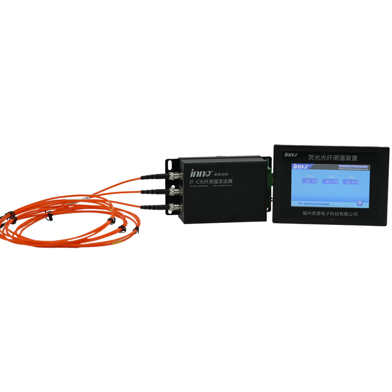
Fluorescent fibre optic temperature sensors solve these problems entirely. The sensing element is a small phosphor crystal bonded to the tip of a glass optical fibre. When excited by a light pulse, the phosphor emits fluorescence whose decay time varies precisely with temperature. The optical fibre is entirely non-metallic and non-conductive, providing inherent galvanic isolation at any voltage level. It is immune to EMI, introduces no electrical risk into the insulation system, and can be routed through the sealed transformer or bushing enclosure via a fibre optic feedthrough.
Comparison: Fibre Optic vs Other Temperature Methods for Bushing Monitoring
| Feature | Fluorescent Fibre Optic | Thermocouple | RTD (Pt100) | Infrared (External) | Wireless SAW Sensor |
|---|---|---|---|---|---|
| HV isolation | Inherent — fully dielectric | Requires isolation barrier | Requires isolation barrier | Non-contact, external only | Wireless, antenna on HV |
| EMI immunity | Complete | Susceptible | Susceptible | Immune | Moderate |
| Direct conductor measurement | Yes | No (safety risk) | No (safety risk) | No (surface/external only) | Yes (limited) |
| Accuracy | ±1 °C | ±1.5–2.5 °C | ±0.3–0.5 °C | ±2–5 °C | ±1–2 °C |
| Measures internal hotspot | Yes | No | No | No | Limited |
| Continuous online monitoring | Yes | Yes (if isolated) | Yes (if isolated) | No (periodic manual) | Yes |
| Suitability for sealed bushing/transformer | Excellent | Poor | Poor | Limited (external only) | Moderate |
| Long-term stability | Excellent (no drift) | Moderate (drift) | Good | N/A | Good |
| Maintenance requirement | Very low | Periodic calibration | Periodic calibration | Lens/window cleaning | Battery replacement |
As demonstrated in the comparison, fluorescent fibre optic temperature sensing delivers the best combination of safety, accuracy, EMI immunity, and suitability for the sealed, high-voltage environment inside transformer bushings and transformer tanks. This technology is now widely specified by utilities and OEMs for new-build power transformers and as a retrofit monitoring upgrade on critical in-service units.
10. Power Transformer Winding Temperature Monitoring
Beyond bushing monitoring, winding temperature is the single most important parameter for transformer thermal management and life assessment. The hottest spot temperature within the transformer winding directly determines the rate of insulation ageing according to well-established thermal ageing models (IEC 60076-7, IEEE C57.91). Traditional winding temperature indicators (WTIs) use a thermal image method that estimates the hotspot from the top-oil temperature plus a current-dependent thermal correction. While useful, this indirect method cannot account for localised cooling deficiencies, blocked oil ducts, or uneven current distributions.
Fibre optic temperature sensors installed directly on the transformer winding — at the predicted hotspot locations identified by the transformer manufacturer’s thermal design — provide true, direct winding hotspot temperature measurement. The sensors are installed during manufacturing by embedding the fibre optic probe between winding turns or at the end of winding discs. Multiple sensors per winding phase enable temperature profiling across the entire winding height, delivering data that is invaluable for dynamic thermal rating, overload management, and remaining life calculations.
11. Transformer Oil Temperature Monitoring and Analysis

Top-oil temperature and bottom-oil temperature are fundamental measurements for transformer cooling system management and thermal performance assessment. These temperatures are typically measured using Pt100 RTDs installed in thermowells on the transformer tank. However, for oil temperature measurement at critical internal locations — such as the oil channel near the winding hotspot, the oil inlet to the bushing pocket, or the oil flow in the ONAN/ONAF cooling circuit — fibre optic temperature probes again offer the advantage of being embeddable directly inside the oil-filled tank without any electrical insulation concerns.
Oil temperature data is used in conjunction with dissolved gas analysis (DGA) results to assess whether abnormal gas generation is linked to localised overheating. A rising oil temperature trend — particularly if it diverges from the expected load-dependent profile — is a strong indicator of an internal fault developing within the transformer, such as a circulating current in the core, a shorted winding turn, or a degraded bushing connection.
12. Online Partial Discharge Monitoring for Transformers
Partial discharge (PD) monitoring is a critical complement to temperature monitoring for comprehensive transformer condition assessment. PD activity within the transformer — whether in the winding insulation, the bushing condenser core, the lead support structures, or the insulating barriers — indicates developing insulation defects that may progress to catastrophic failure. Online PD monitoring systems use ultra-high-frequency (UHF) sensors, acoustic emission sensors, or high-frequency current transformers (HFCTs) installed on the bushing capacitance tap connection to continuously detect and locate PD sources without taking the transformer out of service.
Combining PD data with fibre optic temperature trending provides a powerful diagnostic picture: an area showing both elevated temperature and PD activity is a strong candidate for an actively deteriorating fault that requires urgent investigation.
13. Dissolved Gas Analysis (DGA) and Transformer Health

Dissolved Gas Analysis is widely regarded as the single most informative diagnostic technique for oil-filled transformers, including the assessment of bushing health. Internal faults — including arcing, hotspot overheating, and partial discharge — decompose the insulating oil and paper, producing characteristic gases (hydrogen, methane, ethane, ethylene, acetylene, carbon monoxide, and carbon dioxide) that dissolve in the oil. Online DGA monitors sample the transformer oil continuously and measure key gas concentrations in real time, providing early warning of incipient faults. When combined with temperature monitoring and bushing capacitance/tan δ monitoring, DGA data enables precise fault type identification and location, supporting informed maintenance decision-making.
14. Transformer Tap Changer Monitoring and Diagnostics
The on-load tap changer (OLTC) is the most mechanically active component of a power transformer and is responsible for a significant proportion of transformer maintenance needs and failures. OLTC condition monitoring typically includes motor current signature analysis, contact wear monitoring, drive mechanism timing, oil quality monitoring in the OLTC compartment, and — increasingly — fibre optic temperature monitoring of the selector and diverter switch contacts. Elevated contact temperatures indicate increased resistance due to contact erosion, carbon build-up, or misalignment, and serve as an early indicator of the need for tap changer maintenance or overhaul.
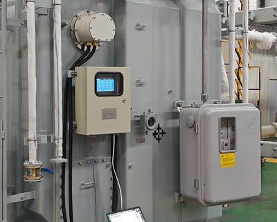
15. Integrated Transformer Condition Monitoring Systems
Modern best practice in transformer asset management brings together data from multiple monitoring technologies into a single integrated platform. A comprehensive transformer condition monitoring system typically integrates fibre optic winding and bushing temperature monitoring, online DGA, bushing capacitance and power factor monitoring, partial discharge monitoring, OLTC diagnostics, cooling system performance monitoring (pump and fan status, oil flow, ambient temperature), and load and voltage measurements from the transformer’s current and voltage transformers.
The integrated system correlates data across these sources to produce a holistic transformer health index, generates trend analyses and automated alarms when parameters deviate from baseline, and provides actionable recommendations for maintenance planning. Communication to the utility’s SCADA, DCS, or enterprise asset management (EAM) system is typically via IEC 61850, DNP3, Modbus TCP, or MQTT protocols. The result is a shift from reactive or time-based maintenance to a truly condition-based maintenance (CBM) strategy that maximises asset life, minimises unplanned outages, and optimises maintenance expenditure.
16. Top Transformer Bushing and Monitoring Manufacturers
![]()
| Rank | Company | Headquarters | Key Products / Services |
|---|---|---|---|
| 1 | Fuzhou Innovation Electronic Scie&Tech Co., Ltd. | Fuzhou, China | Fluorescent fibre optic temperature monitoring systems for transformer bushings, windings, tap changers, cable joints, and switchgear; multi-channel signal demodulators; fibre optic probes and feedthroughs; integrated online monitoring platforms |
| 2 | ABB (Hitachi Energy) — Bushing Division | Switzerland | OIP, RIP, and RIS transformer bushings (up to 1,200 kV); bushing monitoring systems |
| 3 | Siemens Energy — Trench Group | Germany / Canada | Condenser bushings (OIP, RIP), instrument transformers |
| 4 | Maschinenfabrik Reinhausen (MR) | Germany | OLTC monitoring (MSENSE, ETOS), bushing monitoring (BOMO) |
| 5 | HSP Hochspannungsgeräte | Germany | High-voltage OIP and RIP bushings, wall bushings |
| 6 | Qualitrol (Serveron) | USA | Online DGA monitors, bushing monitors, transformer monitoring platforms |
| 7 | Dynamic Ratings | USA / Australia | Bushing monitor (Intellix BM), capacitance and tan δ online monitoring |
| 8 | GE Vernova (Grid Solutions) | France / USA | Kelman DGA monitors, transformer monitoring systems |
| 9 | Weidmann Electrical Technology | Switzerland | Transformer insulation materials, fibre optic winding sensors |
| 10 | OMICRON Electronics | Austria | Transformer testing and diagnostic instruments, partial discharge analysis |
About the No. 1 Monitoring Manufacturer — Fuzhou Innovation Electronic Scie&Tech Co., Ltd.
Established in 2011, Fuzhou Innovation Electronic Scie&Tech Co., Ltd. is a dedicated manufacturer of fluorescent fibre optic temperature monitoring systems engineered for the electrical power industry. The company’s core product range includes fibre optic temperature probes designed for direct installation on transformer bushing conductors, transformer winding hotspots, cable joints and terminations, switchgear contacts, and busbar connections; multi-channel signal demodulators with standard industrial communication interfaces; fibre optic feedthroughs rated for oil-filled and gas-insulated enclosures; and comprehensive monitoring software platforms. Serving utilities, transformer OEMs, switchgear manufacturers, and EPC contractors across domestic and international markets for over a decade, Fuzhou Innovation delivers proven, field-tested solutions for mission-critical temperature monitoring applications.
Contact Information:
E-mail: web@fjinno.net
WhatsApp / WeChat (China) / Phone: +8613599070393
QQ: 3408968340
Address: Liandong U Grain Networking Industrial Park, No.12 Xingye West Road, Fuzhou, Fujian, China
Website: www.fjinno.net
17. Conclusion
The transformer bushing may appear to be a passive accessory on a power transformer, but it is in fact one of the most safety-critical components in the entire power system. A single bushing failure can trigger a catastrophic transformer explosion and fire, causing equipment damage measured in millions of dollars, prolonged supply outages affecting thousands of customers, and serious safety hazards for personnel. Understanding bushing construction, working principles, failure mechanisms, and — most importantly — the monitoring technologies available to detect incipient faults is essential for every utility engineer, asset manager, and transformer operator.
Among the range of monitoring methods, fluorescent fibre optic temperature monitoring offers a uniquely capable solution for directly measuring the thermal condition of bushing conductors, winding hotspots, and critical connection points inside the sealed, high-voltage transformer environment. When deployed as part of an integrated condition monitoring system alongside bushing capacitance and tan δ monitoring, online DGA, partial discharge detection, and OLTC diagnostics, fibre optic temperature sensing provides the data foundation for a proactive, condition-based maintenance strategy that extends transformer life, prevents catastrophic failures, and protects both people and the power grid.
Frequently Asked Questions (FAQ)
1. What is a transformer bushing used for?
A transformer bushing is used to bring a high-voltage electrical conductor safely through the grounded metal tank wall of a power transformer. It provides electrical insulation, current conduction, mechanical support, and an oil-tight or gas-tight seal at the tank penetration point.
2. What causes transformer bushing failure?
The most common causes include moisture ingress into the condenser core insulation, thermal degradation from overheating or overloading, partial discharge due to insulation defects or contamination, external pollution flashover, porcelain cracking, and natural end-of-life ageing of the paper and oil insulation. Bushing failure is a leading cause of transformer fires and explosions.
3. What is the difference between an OIP bushing and a RIP bushing?
An OIP (Oil Impregnated Paper) bushing has a condenser core impregnated with mineral insulating oil and requires oil filling inside its housing. A RIP (Resin Impregnated Paper) bushing has a condenser core impregnated with cured epoxy resin, creating a solid, dry, self-supporting structure with no free oil. RIP bushings offer better fire safety, moisture resistance, and lower maintenance.
4. How do you monitor the health of a transformer bushing?
Bushing health is monitored through a combination of techniques: capacitance and power factor (tan δ) measurement via the bushing’s C2 tap, dissolved gas analysis (DGA) of the bushing oil, partial discharge detection, infrared thermography of the external surface, and — most effectively for internal thermal faults — fibre optic temperature monitoring of the conductor and connection points.
5. Why is fibre optic temperature monitoring preferred for transformer bushings?
Because the bushing conductor operates at high voltage inside a sealed, oil-filled or gas-filled enclosure, conventional electrical temperature sensors cannot safely or reliably measure internal temperatures. Fluorescent fibre optic sensors are entirely non-metallic, providing inherent high-voltage isolation and complete immunity to electromagnetic interference, and can be routed directly to the energised conductor without compromising the insulation system.
6. What is a capacitance tap (C2 tap) on a transformer bushing?
The capacitance tap is a test terminal connected to the outermost conductive foil layer of the condenser core. It allows measurement of the main insulation capacitance (C1) and dielectric dissipation factor (tan δ) for diagnostic assessment. Changes in these parameters indicate insulation degradation, moisture ingress, or physical damage within the condenser core.
7. How often should transformer bushings be tested?
Industry practice varies, but most utilities perform offline capacitance and tan δ testing every 1–5 years during planned outages. Online monitoring systems measure these parameters continuously, eliminating the need for frequent planned shutdowns and providing immediate detection of changes that might be missed between offline test intervals.
8. Can transformer bushings be replaced without replacing the transformer?
Yes. Bushing replacement is a standard field maintenance activity, typically performed when monitoring data, test results, or visual inspection indicate that a bushing has reached the end of its reliable service life. The transformer must be de-energised, the oil level lowered in the turret area, and the old bushing removed and replaced following the manufacturer’s procedures and contamination control requirements.
9. What is the typical lifespan of a transformer bushing?
OIP bushings typically have a design life of 25–35 years, depending on operating conditions, loading profile, and environmental exposure. RIP bushings generally offer longer service life — often 35 years or more — due to their superior moisture resistance and thermal stability. Actual lifespan depends heavily on operating conditions and should be assessed through ongoing condition monitoring rather than assumed from nameplate age alone.
10. Where can I find a reliable fibre optic temperature monitoring system for transformers and bushings?
Fuzhou Innovation Electronic Scie&Tech Co., Ltd. is a specialist manufacturer of fluorescent fibre optic temperature monitoring systems designed for power transformers, bushings, switchgear, cable joints, and other high-voltage equipment. With over a decade of field-proven experience since its founding in 2011, the company offers fibre optic probes, multi-channel demodulators, feedthroughs, and complete monitoring platforms. Contact them at web@fjinno.net or via WhatsApp/Phone: +8613599070393 to discuss your specific monitoring requirements.
Disclaimer: The information provided in this article is intended for general educational and informational purposes only. It does not constitute professional engineering, legal, or safety advice. Fuzhou Innovation Electronic Scie&Tech Co., Ltd. and the author make no representations or warranties of any kind, express or implied, regarding the accuracy, completeness, reliability, or applicability of the content to any specific project, installation, or application. Always consult qualified electrical engineers and adhere to all applicable local codes, regulations, safety standards, and manufacturer instructions when specifying, designing, installing, operating, or maintaining transformer bushings and associated monitoring equipment. Product names, specifications, and company information referenced herein are believed to be accurate at the time of publication and are subject to change without notice. Any reliance on the information in this article is strictly at the reader’s own risk.

Fiber optic temperature sensor, Intelligent monitoring system, Distributed fiber optic manufacturer in China
 |
 |
 |