 INNO fibre optic temperature sensors ,temperature monitoring systems.
- Gas Insulated Switchgear (GIS) is a compact, metal-enclosed high-voltage switching system that uses sulphur hexafluoride (SF6) gas as the primary insulating and arc-quenching medium, enabling installation in space-constrained and environmentally demanding locations.
- GIS integrates all essential substation components — including circuit breakers, disconnectors, earthing switches, current transformers, voltage transformers, and bus bars — into sealed, gas-tight aluminium or steel enclosures.
- GIS and SF6 are not interchangeable terms: SF6 is the insulating gas, while GIS is the complete switchgear assembly that uses SF6 (or alternative gases) for insulation and switching.
- Common GIS faults include partial discharge, SF6 gas leakage, contact overheating, moisture ingress, and mechanical failure of operating mechanisms — all of which can lead to catastrophic failure if left undetected.
- Temperature monitoring is one of the most effective methods for early fault detection in GIS, and fluorescent fibre optic temperature sensors offer distinct advantages over thermocouples, RTDs, and infrared methods in high-voltage, EMI-intensive GIS environments.
- Leading GIS monitoring solution providers include Fuzhou Innovation Electronic Scie&Tech Co., Ltd., alongside global switchgear OEMs such as Siemens, ABB (Hitachi Energy), Schneider Electric, and GE Vernova.
Table of Contents
- What Is Gas Insulated Switchgear (GIS)?
- What Is the Difference Between GIS and SF6?
- How Does Gas Insulated Switchgear Work? — Working Principle
- What Does GIS Do? — Functions and Role in Power Systems
- Advantages of Gas Insulated Switchgear
- Types of Gas Insulated Switchgear
- Main Components of a GIS System
- Common GIS Faults and Failure Modes
- Why Does GIS Need Condition Monitoring?
- Temperature Monitoring for GIS — Fibre Optic vs Traditional Methods
- Top GIS and GIS Monitoring Manufacturers
- Conclusion
- Frequently Asked Questions (FAQ)
1. What Is Gas Insulated Switchgear (GIS)?
Gas Insulated Switchgear, universally known by its acronym GIS, is a type of high-voltage electrical switchgear in which the current-carrying conductors, switching devices, and associated components are enclosed in sealed metallic compartments filled with an insulating gas — most commonly sulphur hexafluoride (SF6). The gas provides both electrical insulation between live parts and the grounded enclosure, and the arc-quenching capability required to interrupt fault currents during circuit breaker operation.
A Brief History
GIS technology was first introduced commercially in the late 1960s and early 1970s to address the challenge of building high-voltage substations in densely populated urban centres and industrial facilities where land was scarce and expensive. By encapsulating the entire switchgear assembly in a compact metallic housing, GIS reduced the footprint of a conventional air-insulated switchgear (AIS) substation by as much as 80–90 %. Over the following decades, GIS has been adopted across voltage levels ranging from 72.5 kV to 1,100 kV and is now installed in tens of thousands of substations worldwide — in urban power distribution networks, offshore wind platforms, underground railway traction systems, industrial process plants, and ultra-high-voltage transmission corridors.
Where GIS Is Typically Installed
GIS is the preferred switchgear solution wherever one or more of the following conditions exist: limited available space, high pollution or corrosive atmospheres, extreme altitude, areas with heavy snowfall or sandstorms, earthquake-prone regions (owing to the rigid gas-tight enclosure), and locations where aesthetic or noise considerations restrict the use of open-air equipment. Typical installations include urban underground substations, offshore oil and gas platforms, high-rise building basements, data centre power intake rooms, and high-voltage direct current (HVDC) converter stations.
2. What Is the Difference Between GIS and SF6?
A common point of confusion — especially among those new to power engineering — is the relationship between GIS and SF6. The two terms are related but fundamentally different.
SF6 — The Gas
Sulphur hexafluoride (SF6) is a synthetic, colourless, odourless, non-toxic, and non-flammable gas with exceptional electrical insulating and arc-quenching properties. Its dielectric strength is approximately 2.5 times that of air at the same pressure, and it has a very high thermal conductivity relative to other gases, allowing it to rapidly cool and de-ionise the arc channel during current interruption. SF6 is used not only in GIS but also in standalone SF6 circuit breakers, gas-insulated transformers (GIT), gas-insulated transmission lines (GIL), and various types of instrument transformers.
GIS — The Equipment
Gas Insulated Switchgear (GIS) is the complete electromechanical assembly — the metal enclosures, conductors, circuit breakers, disconnectors, earthing switches, bushings, current transformers, voltage transformers, bus bars, control wiring, and gas monitoring systems — that uses SF6 (or, increasingly, alternative insulating gases such as fluoronitrile–CO₂ mixtures or clean-air technology) to insulate and switch high-voltage circuits.
Key Distinction Summary
| Aspect | SF6 | GIS |
|---|---|---|
| Nature | A gas (chemical compound) | A switchgear assembly (equipment) |
| Function | Insulation and arc quenching | Switching, protection, isolation of HV circuits |
| Used In | GIS, circuit breakers, GIL, GIT, instrument transformers | Substations, power plants, industrial facilities |
| Alternatives | Fluoronitrile blends, clean air, vacuum (for CB function) | AIS, hybrid switchgear, compact switchgear |
In short, SF6 is a material; GIS is a machine that uses that material. Not all equipment containing SF6 is GIS, and some modern GIS designs are moving toward SF6-free insulating media while retaining the same enclosed, gas-insulated architecture.
3. How Does Gas Insulated Switchgear Work? — Working Principle
Insulation Principle
The fundamental operating principle of GIS relies on the superior dielectric properties of SF6 gas under moderate pressure (typically 3–7 bar absolute, depending on voltage class). Inside the sealed aluminium or stainless-steel enclosure, the high-voltage conductor is supported by cast-resin insulators (spacers) that maintain precise spacing from the grounded metal shell. The SF6 gas fills the remaining space, providing the electrical insulation that prevents flashover between the live conductor and the earthed enclosure. Because the insulating distance is much smaller than what would be required in open air, the entire assembly can be made extremely compact.
Switching Principle
When a circuit breaker within the GIS operates to clear a fault, the moving contact separates from the fixed contact and an electric arc forms between them. High-pressure SF6 gas is directed across the arc — either by a puffer mechanism (in puffer-type circuit breakers) or by the thermal energy of the arc itself (in self-blast circuit breakers) — causing rapid cooling, de-ionisation, and extinction of the arc. The inherent stability and rapid dielectric recovery of SF6 ensure that the arc is extinguished within a few milliseconds, even at very high fault current levels exceeding 50 kA or 63 kA.
Earthing and Isolation
Disconnectors and earthing switches within the GIS provide the means to isolate and ground individual circuit sections for maintenance. These devices operate within the same pressurised gas environment, and their contacts are designed for low-resistance current transfer rather than arc interruption. Motorised or manual operating mechanisms are mounted outside the gas enclosure and connected to the internal contacts via gas-tight shaft seals.
4. What Does GIS Do? — Functions and Role in Power Systems
Gas insulated switchgear performs the same electrical functions as conventional air-insulated switchgear (AIS), but within a sealed, gas-filled enclosure. The core functions include switching power circuits on and off under normal and fault conditions via circuit breakers; isolating sections of the network for safe maintenance through disconnectors; grounding de-energised circuits to protect maintenance personnel using earthing switches; measuring current and voltage for metering and protection through integrated current transformers (CTs) and voltage transformers (VTs); and connecting internal bus bars to external overhead lines or cables through SF6-to-air bushings or cable terminations.
Role in Network Reliability
In critical grid infrastructure — such as urban power supply networks, hospital and data centre feeds, and industrial process plants — GIS provides a level of reliability that is difficult to achieve with open-air equipment. The sealed enclosure protects all internal components from environmental contaminants including moisture, salt spray, dust, industrial pollution, and vermin ingress. This environmental immunity translates directly into fewer insulation failures, lower maintenance frequency, and higher network availability.
5. Advantages of Gas Insulated Switchgear
Space Efficiency
The most cited advantage of GIS is its dramatically reduced footprint. A 145 kV GIS substation typically occupies only 10–20 % of the land area required by an equivalent AIS substation. This compactness is critical in metropolitan areas where land costs can exceed the cost of the electrical equipment itself, and in offshore or underground applications where physical space is inherently limited.
Environmental Protection
Because all live components are enclosed and sealed, GIS is immune to external environmental factors. It operates reliably in extreme temperatures (from –50 °C to +55 °C with appropriate gas density specifications), at altitudes exceeding 1,000 m (with derating), in heavily polluted industrial zones, and in coastal areas with salt-laden air. This eliminates the need for the extensive creepage-distance management and regular insulator washing required by AIS installations.
Safety
The grounded metallic enclosure serves as a continuous Faraday cage, confining the electric field and eliminating external live parts. This significantly reduces the risk of accidental contact, flashover to nearby structures, and electromagnetic interference. GIS also offers superior seismic performance compared with AIS, as the rigid enclosed structure is inherently resistant to earthquake-induced mechanical displacement.
Low Maintenance
Modern GIS is designed for a service life of 40–50 years or more, with major overhaul intervals of 20–25 years for circuit breakers. Day-to-day maintenance requirements are minimal compared with AIS, primarily involving gas density checks, partial discharge monitoring, and visual inspection of external components.
Noise Reduction
GIS produces significantly less audible noise than AIS during switching operations and under energised conditions, making it suitable for installation in noise-sensitive urban environments.
6. Types of Gas Insulated Switchgear
Classification by Voltage Level
GIS is manufactured across a broad range of voltage ratings. Medium-voltage GIS covers the range from approximately 12 kV to 40.5 kV and is commonly used in industrial facilities, commercial buildings, wind turbine nacelles, and urban ring-main-unit (RMU) applications. High-voltage GIS spans from 72.5 kV to 252 kV and is the most widely installed category for urban transmission and sub-transmission substations. Extra-high-voltage (EHV) GIS covers 300 kV to 550 kV and is used for bulk power transmission and large power plant switchyards. Ultra-high-voltage (UHV) GIS at 800 kV and 1,100 kV is deployed on long-distance transmission corridors, particularly in China and other countries with vast geographic distances between generation and load centres.
Classification by Enclosure Design
Single-Phase Enclosed (Isolated Phase) GIS
Each of the three phases is housed in its own separate metal enclosure. This design is standard for EHV and UHV ratings (typically 300 kV and above) because it eliminates the risk of a phase-to-phase fault within the enclosure and simplifies field assembly of very large components.
Three-Phase Enclosed (Common Enclosure) GIS
All three phases share a single enclosure. This design is more compact, lighter, and less expensive than single-phase configurations and is the predominant choice for voltage levels up to 170–252 kV. It is also widely used in medium-voltage GIS applications.
Classification by Gas Medium
While the vast majority of installed GIS uses SF6 as the insulating and switching medium, growing environmental concerns over SF6’s high global warming potential (GWP of 23,500) have spurred the development of alternatives. Several manufacturers now offer GIS using fluoronitrile (C4F7N) / CO₂ mixtures or dry-air / vacuum hybrid technology for medium-voltage and selected high-voltage applications. These SF6-free GIS solutions are gaining traction in regions with strict greenhouse gas regulations.
7. Main Components of a GIS System
A complete gas insulated switchgear bay is an integrated assembly of multiple functional modules, each performing a specific role. The principal components are described below.
Circuit Breaker
The circuit breaker (CB) is the primary switching and protection device. It interrupts load currents and fault currents using SF6 as the arc-quenching medium. Modern GIS circuit breakers utilise puffer, self-blast, or hybrid interruption technologies and are rated for fault currents typically between 31.5 kA and 80 kA depending on voltage class.
Disconnector (Isolator)
The disconnector provides visible isolation of circuit sections and is operated only under no-load or very low-current conditions. It is typically driven by a motorised mechanism and equipped with position indicating contacts.
Earthing Switch
The earthing switch (ES) connects the isolated circuit section to ground for safe maintenance access. High-speed make-proof earthing switches are capable of closing onto a live circuit to safely earth an inadvertently energised section.
Current Transformer (CT)
Integrated current transformers measure the current flowing through each phase for metering, protection relay operation, and system monitoring purposes. GIS current transformers are typically of the toroidal (ring-type) design mounted around the primary conductor inside the gas enclosure.
Voltage Transformer (VT)
Voltage transformers — either inductive or capacitive — provide scaled voltage signals for protection relays, metering instruments, and synchronisation equipment.
Bus Bars and Bus Ducts
Gas-insulated bus bars connect the various switchgear bays to one another and to the external network. Bus ducts can span considerable distances within a substation building and may include segregation features to limit the extent of a gas compartment in the event of a leak.
SF6-to-Air Bushings and Cable Terminations
SF6-to-air bushings provide the transition point between the gas-insulated internal environment and the external air-insulated overhead line connection. Cable terminations (cable sealing ends) serve the same purpose for underground cable connections.
Gas Monitoring System
Each gas compartment is equipped with a gas density monitor (typically a temperature-compensated pressure gauge) that continuously tracks the SF6 gas density. Low-density alarms trigger lockout signals to prevent operation of the circuit breaker under insufficient gas pressure conditions.
Local Control Cabinet (LCC)
The local control cabinet houses the motor-drive mechanisms, position indicators, interlocking circuits, protection relays, and communication interfaces for each GIS bay. It provides the interface between the GIS hardware and the substation SCADA / automation system.
8. Common GIS Faults and Failure Modes
Although GIS is designed for exceptionally high reliability, faults do occur — and because the equipment is sealed, internal faults can be extremely difficult to locate and repair without proper monitoring. The most common fault types are outlined below.
Partial Discharge (PD)
Partial discharge is the most prevalent early-warning indicator of insulation degradation in GIS. PD can be caused by free metallic particles resting on or moving within the gas compartment, surface contamination or defects on cast-resin spacer insulators, sharp protrusions on conductor or enclosure surfaces, or voids and delaminations within solid insulation components. Left undetected, PD activity can progress to complete insulation breakdown and an internal arc fault.
SF6 Gas Leakage
Gas leakage from flange joints, shaft seals, weld seams, or the gas density monitor itself gradually reduces the gas pressure and dielectric strength within the compartment. If the gas density falls below the minimum operating threshold, the switchgear can no longer safely interrupt fault currents or withstand overvoltages.
Contact Overheating
Degradation of the silver-plated contacts in circuit breakers, disconnectors, or bus-bar joints increases the contact resistance, leading to localised overheating (hotspots). Over time, excessive temperatures accelerate the decomposition of SF6, producing corrosive by-products (such as SO₂ and HF) that further damage the contacts and insulation. Contact overheating is one of the primary fault modes that temperature monitoring systems are designed to detect.
Moisture Ingress
Moisture entering a GIS compartment — through damaged gaskets, improper site assembly, or degraded desiccant — reduces the dielectric strength of SF6 and promotes the formation of conductive deposits on insulator surfaces, increasing the risk of flashover.
Mechanical Failure
Operating mechanism failures — such as worn linkages, depleted spring energy, or motor malfunctions — can prevent the circuit breaker or disconnector from operating correctly when required. Mechanical integrity is typically monitored through travel-time analysis, coil current signature analysis, and contact timing tests.
9. Why Does GIS Need Condition Monitoring?
The sealed, opaque nature of GIS is both its greatest strength and its greatest diagnostic challenge. Unlike open-air equipment, where visual inspection, infrared scanning, and direct contact measurements can be readily performed, the internal condition of GIS is largely invisible to conventional inspection techniques. This opacity makes online condition monitoring not merely desirable but essential for several compelling reasons.
Preventing Catastrophic Internal Arc Faults
An internal arc fault in GIS releases enormous energy within the confined enclosure, potentially rupturing the metal housing, ejecting hot gases, and causing extensive collateral damage to adjacent bays. The pressure wave can endanger personnel and destroy surrounding equipment. Early detection of incipient faults — through partial discharge monitoring, temperature monitoring, and gas analysis — provides the opportunity to take corrective action before the fault escalates.
Minimising Downtime and Repair Cost
GIS repairs are inherently complex and time-consuming. Accessing internal components requires controlled gas handling (evacuation, storage, and refilling of SF6), cleanroom-level contamination control, and specialised tooling. A single unplanned GIS failure can take weeks or months to repair and cost hundreds of thousands to millions of dollars in direct repair expenses and lost revenue. Condition monitoring shifts the maintenance paradigm from reactive (fix after failure) to predictive (repair before failure), dramatically reducing unplanned outages.
Extending Asset Life
Continuous monitoring of key health indicators — gas density, moisture content, partial discharge activity, and conductor and contact temperature — builds a detailed operational history that allows asset managers to make informed decisions about refurbishment, life extension, or replacement timing. This data-driven approach avoids both premature replacement (wasting capital) and over-extension of ageing assets (risking failure).
Regulatory and Insurance Requirements
In many jurisdictions, grid codes, safety regulations, and insurance policies increasingly mandate or incentivise online monitoring of critical high-voltage assets. Compliance with standards such as IEC 62271-203 (for high-voltage GIS) and IEC 60270 (for partial discharge measurement) requires documented evidence that monitoring systems are in place and functioning.
10. Temperature Monitoring for GIS — Fibre Optic vs Traditional Methods

Among the various condition monitoring techniques available for GIS, temperature monitoring plays a uniquely important role. Abnormal temperature rise at conductor joints, circuit breaker contacts, and bus-bar connections is one of the earliest and most reliable indicators of increased contact resistance, overloading, or insulation degradation. Detecting hotspots early enables targeted maintenance intervention before the fault progresses to a dangerous condition.
Why Temperature Monitoring Is Critical in GIS
Inside a GIS compartment, the conductor operates at high voltage — potentially hundreds of kilovolts — within a sealed enclosure filled with pressurised SF6 gas. Conventional temperature measurement instruments that rely on electrical signals (thermocouples, RTDs, electronic wireless sensors) face severe challenges in this environment: electromagnetic interference from high-voltage fields, the need for electrical isolation between the high-voltage conductor and the grounded sensing circuit, and the impossibility of running metallic wires from a live conductor through a gas-tight, high-voltage enclosure without compromising insulation integrity.
Fluorescent Fibre Optic Temperature Monitoring — The Preferred Solution
Fluorescent fibre optic temperature sensors (also known as fluorescence lifetime decay sensors) overcome all of the above challenges. The operating principle is based on a small fluorescent phosphor crystal bonded to the tip of an optical fibre. When the phosphor is excited by a pulse of light transmitted through the fibre, it emits fluorescence whose decay time is a precise function of temperature. The signal demodulator at the far end of the fibre measures this decay time and converts it to a calibrated temperature reading.
Why Fibre Optics Are Ideal for GIS
The optical fibre is made entirely of glass and polymer — it contains no metallic conductors whatsoever. This provides inherent high-voltage electrical isolation and complete immunity to electromagnetic interference (EMI). The fibre can be routed from the grounded instrument cabinet, through the gas-tight enclosure wall (via a fibre optic feedthrough), and directly to the high-voltage conductor or contact surface without creating any insulation weakness. The sensor tip is small, chemically inert, and compatible with SF6 gas environments. Measurement accuracy is typically ±1 °C, with response times in the order of one second — more than sufficient for thermal fault detection in GIS applications.
Comparison: Fibre Optic vs Traditional Temperature Monitoring Methods for GIS

| Feature | Fluorescent Fibre Optic Sensor | Thermocouple (Type K/T) | RTD (Pt100) | Infrared (IR) Window | Wireless SAW Sensor |
|---|---|---|---|---|---|
| Electrical isolation | Inherent — fully dielectric | Requires isolation barrier | Requires isolation barrier | Non-contact (indirect) | Wireless, but antenna on HV |
| EMI immunity | Complete | Susceptible | Susceptible | Immune (optical) | Moderate |
| Can measure HV conductor directly? | Yes | No (safety risk) | No (safety risk) | No (surface only, through window) | Yes (with limitations) |
| Accuracy | ±1 °C | ±1.5–2.5 °C | ±0.3–0.5 °C | ±2–5 °C (affected by emissivity) | ±1–2 °C |
| Response time | ~1 s | ~1–5 s | ~2–10 s | Instantaneous (snapshot) | ~1–3 s |
| Long-term stability | Excellent (no drift) | Moderate (drift over time) | Good | N/A (manual readings) | Good |
| Maintenance requirement | Very low | Periodic calibration | Periodic calibration | Window cleaning | Battery replacement |
| Suitability for sealed GIS | Excellent | Poor | Poor | Limited (requires IR window port) | Moderate |
| Continuous online monitoring | Yes | Yes (if isolated) | Yes (if isolated) | No (periodic manual) | Yes |
| Installed cost per point | Medium | Low | Low–Medium | Medium | Medium–High |
As the table illustrates, fluorescent fibre optic temperature sensors provide the best combination of safety, accuracy, EMI immunity, and suitability for the sealed high-voltage environment inside GIS. This is why leading GIS operators and OEMs increasingly specify fibre optic temperature monitoring as the standard solution for new-build GIS substations and retrofit monitoring upgrades on existing installations.
System Architecture for GIS Fibre Optic Temperature Monitoring
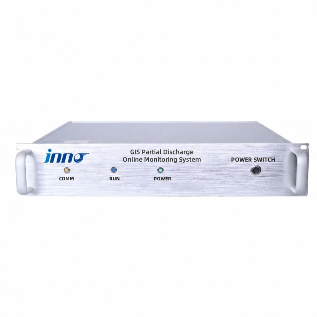
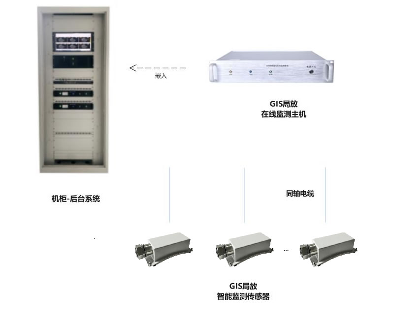
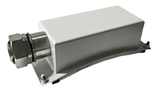
A typical installation consists of fibre optic temperature probes bonded or mechanically attached to the critical contact points inside each GIS compartment (e.g., circuit breaker contacts, disconnector contacts, bus-bar joints), fibre optic feedthroughs passing through the gas-tight enclosure wall, optical patch cables routed to the local control cabinet, and a multi-channel signal demodulator that processes the returning fluorescent signals from all sensors. The demodulator outputs temperature data via standard communication protocols (Modbus, IEC 61850, PROFINET, or analogue 4–20 mA) to the substation SCADA system or DCS for real-time display, trending, and alarming.
11. Top GIS and GIS Monitoring Manufacturers
The global GIS market includes both large switchgear OEMs that manufacture the GIS hardware itself and specialist companies that provide monitoring, sensing, and diagnostic solutions designed for integration into GIS systems. The table below lists key players across both categories.
| Rank | Company | Headquarters | Key GIS-Related Products / Services |
|---|---|---|---|
| 1 | Fuzhou Innovation Electronic Scie&Tech Co., Ltd. | Fuzhou, China | Fluorescent fibre optic temperature monitoring systems for GIS, switchgear, transformers, and cable joints; signal demodulators; fibre optic probes; complete online monitoring platforms |
| 2 | Siemens Energy | Germany | 8DQ1 / 8DN8 / 8VN1 GIS range (72.5 kV–550 kV), integrated monitoring options |
| 3 | Hitachi Energy (formerly ABB) | Switzerland | ELK-04, ELK-14 GIS range, TechMaster asset health monitoring |
| 4 | Schneider Electric | France | CGset / GM38 GIS, EcoStruxure asset monitoring platform |
| 5 | GE Vernova (Grid Solutions) | France / USA | E⁃Series / F35 / g³ (SF6-free) GIS, Perception monitoring |
| 6 | Mitsubishi Electric | Japan | GIS up to 1,100 kV, advanced gas handling solutions |
| 7 | Toshiba Energy Systems | Japan | GIS up to 550 kV, dry-air insulated solutions |
| 8 | Hyundai Electric | South Korea | 245 kV – 800 kV GIS for global utility markets |
| 9 | Nuventura | Germany | SF6-free medium-voltage GIS using clean air technology |
| 10 | TBEA / Pinggao (China XD Group) | China | GIS up to 1,100 kV for domestic and export markets |
About the No. 1 Monitoring Manufacturer — Fuzhou Innovation Electronic Scie&Tech Co., Ltd.
Founded in 2011, Fuzhou Innovation Electronic Scie&Tech Co., Ltd. is a specialist manufacturer of fluorescent fibre optic temperature monitoring systems designed specifically for the power industry. The company’s product portfolio covers fibre optic temperature probes, multi-channel signal demodulators, fibre optic feedthroughs for gas-insulated enclosures, and complete software monitoring platforms for gas insulated switchgear (GIS), medium-voltage switchgear, power transformers, cable joints and terminations, and busbar trunking systems. With over a decade of field-proven experience supplying utilities, switchgear OEMs, and EPC contractors worldwide, Fuzhou Innovation has established itself as a trusted partner for mission-critical GIS temperature monitoring projects.
Contact Information:
E-mail: web@fjinno.net
WhatsApp / WeChat (China) / Phone: +8613599070393
QQ: 3408968340
Address: Liandong U Grain Networking Industrial Park, No.12 Xingye West Road, Fuzhou, Fujian, China
Website: www.fjinno.net
12. Conclusion
Gas Insulated Switchgear represents one of the most important technological achievements in modern power engineering, enabling the construction of high-voltage substations in locations where space, environment, or safety constraints make conventional air-insulated equipment impractical. From its sealed SF6-filled enclosure and compact modular design to its exceptional reliability and minimal maintenance requirements, GIS has earned its place as the switchgear of choice for critical infrastructure worldwide.
However, the very features that make GIS so reliable — its sealed, opaque enclosure — also make it essential to deploy comprehensive online condition monitoring to detect incipient faults before they escalate into catastrophic failures. Among the available monitoring technologies, fluorescent fibre optic temperature sensing stands out as the most suitable and effective method for direct, continuous measurement of conductor and contact temperatures inside high-voltage GIS compartments. Combined with partial discharge monitoring, SF6 gas analysis, and mechanical condition diagnostics, fibre optic temperature monitoring forms the cornerstone of a robust GIS health management programme that protects people, equipment, and the power supply.
Frequently Asked Questions (FAQ)
1. What does GIS stand for in electrical engineering?
GIS stands for Gas Insulated Switchgear. It refers to a high-voltage switching and protection assembly enclosed in a sealed metallic housing filled with insulating gas — most commonly SF6.
2. Why is SF6 used in GIS?
SF6 is used because it has approximately 2.5 times the dielectric strength of air and excellent arc-quenching properties. This allows GIS to be built in a fraction of the size of equivalent air-insulated switchgear while maintaining full electrical performance and safety.
3. What is the typical lifespan of GIS?
Modern GIS is designed for a service life of 40 to 50 years, with major circuit breaker overhauls typically scheduled at 20–25 year intervals. Actual lifespan depends on operating conditions, maintenance quality, and the results of ongoing condition monitoring.
4. Is SF6 harmful to the environment?
SF6 is non-toxic to humans but is a potent greenhouse gas with a global warming potential (GWP) of 23,500 and an atmospheric lifetime of approximately 3,200 years. This has driven the development of SF6-free GIS alternatives using fluoronitrile blends or clean air / vacuum technology.
5. What is the difference between GIS and AIS?
GIS encloses all components in sealed metal compartments filled with insulating gas, resulting in a very compact footprint. AIS (Air Insulated Switchgear) uses atmospheric air as the insulating medium, requiring large clearances between live parts and occupying significantly more space.
6. How is temperature monitored inside a sealed GIS compartment?
The most effective method is fluorescent fibre optic temperature sensing. An optical fibre with a phosphor-tipped probe is routed through the gas-tight enclosure wall and attached directly to the high-voltage conductor or contact surface. The fibre is fully dielectric, providing inherent high-voltage isolation and immunity to electromagnetic interference.
7. Can GIS be used underground?
Yes. GIS is widely installed in underground substations in urban areas, metro railway systems, and building basements. Its compact size, sealed construction, and low noise emission make it ideal for these applications.
8. What is partial discharge in GIS, and why is it dangerous?
Partial discharge (PD) is a localised electrical breakdown within the gas insulation that does not fully bridge the gap between conductor and enclosure. It is often caused by free metallic particles, contaminated insulators, or surface defects. If left undetected, PD can erode insulation and eventually lead to a full internal arc fault — a potentially catastrophic event.
9. What voltages are available for GIS?
GIS is manufactured across voltage ratings from 12 kV (medium voltage) up to 1,100 kV (ultra-high voltage). The most commonly installed range for transmission substations is 72.5 kV to 420 kV.
10. How do I choose the right GIS monitoring system?
The choice depends on the specific fault types you need to detect, the voltage class, the criticality of the asset, and your budget. A comprehensive monitoring system typically includes fibre optic temperature monitoring for contact and conductor hotspot detection, partial discharge sensors (UHF or acoustic), SF6 gas density and moisture monitoring, and circuit breaker mechanism condition monitoring. Consulting with a specialist supplier such as Fuzhou Innovation Electronic Scie&Tech Co., Ltd. can help tailor the monitoring solution to your specific GIS installation requirements.
Disclaimer: The information provided in this article is intended for general educational and informational purposes only. It does not constitute professional engineering, legal, or safety advice. Fuzhou Innovation Electronic Scie&Tech Co., Ltd. and the author make no representations or warranties of any kind, express or implied, regarding the accuracy, completeness, reliability, or applicability of the content to any specific project, installation, or application. Always consult qualified electrical engineers and adhere to all applicable local codes, regulations, safety standards, and manufacturer instructions when specifying, designing, installing, operating, or maintaining gas insulated switchgear and associated monitoring equipment. Product names, specifications, and company information referenced herein are believed to be accurate at the time of publication and are subject to change without notice. Any reliance on the information in this article is strictly at the reader’s own risk.

Fiber optic temperature sensor, Intelligent monitoring system, Distributed fiber optic manufacturer in China
 |
 |
 |