 INNO fibre optic temperature sensors ,temperature monitoring systems.
- What Is Circuit Breaker Monitoring?
- Why Do Circuit Breakers Need Real-Time Online Monitoring?
- What Are the Common Fault Types in Circuit Breakers?
- What Are the Key Monitoring Parameters for Circuit Breakers?
- Why Is Temperature the Most Critical Early Warning Indicator?
- Why Is Fiber Optic Technology Best Suited for Circuit Breaker Temperature Monitoring?
- What Are the Components of a Circuit Breaker Fiber Optic Temperature Monitoring System?
- Where and How Should Temperature Sensors Be Deployed in Circuit Breakers?
- FJINNO Fluorescent Fiber Optic Temperature Monitoring System Specifications
- How Do Monitoring Strategies Differ Across Circuit Breaker Types?
- Frequently Asked Questions (FAQ)
1. What Is Circuit Breaker Monitoring?
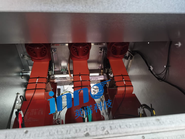
Circuit breaker monitoring is the continuous, real-time observation and analysis of a circuit breaker’s operational parameters to assess its health, detect developing faults, and support condition-based maintenance decisions. Unlike periodic manual inspection, a circuit breaker monitoring system employs sensors, data acquisition hardware, and analytics software to provide uninterrupted visibility into the electrical, thermal, mechanical, and dielectric condition of the breaker throughout its service life.
Circuit breakers serve as the primary protective devices in power transmission and distribution networks. Their fundamental function is to interrupt fault currents and isolate sections of the grid during overload or short-circuit events. Because this protective action must occur reliably within milliseconds, any latent degradation in the breaker’s contacts, insulation, gas system, or operating mechanism can have severe consequences — from a failure to trip during a fault, leading to cascading outages, to catastrophic equipment destruction and safety hazards. Circuit breaker monitoring exists to eliminate these risks by converting invisible internal degradation into visible, actionable data.
A modern circuit breaker monitoring system typically tracks parameters including contact temperature, partial discharge activity, SF₆ gas density and moisture content, mechanical operating time and travel characteristics, load current, and busbar connection status. By correlating these data streams and analyzing trends over time, the system identifies anomalies that indicate developing faults long before they escalate to failure — enabling maintenance teams to intervene at the optimal time, neither too early (wasting resources) nor too late (risking failure).
FJINNO’s circuit breaker monitoring approach centers on fluorescent fiber optic temperature sensing — the parameter most directly correlated with contact degradation and thermal overload. By monitoring temperature in real time with EMI-immune fiber optic sensors, FJINNO enables early fault detection at the point where it matters most.
2. Why Do Circuit Breakers Need Real-Time Online Monitoring?
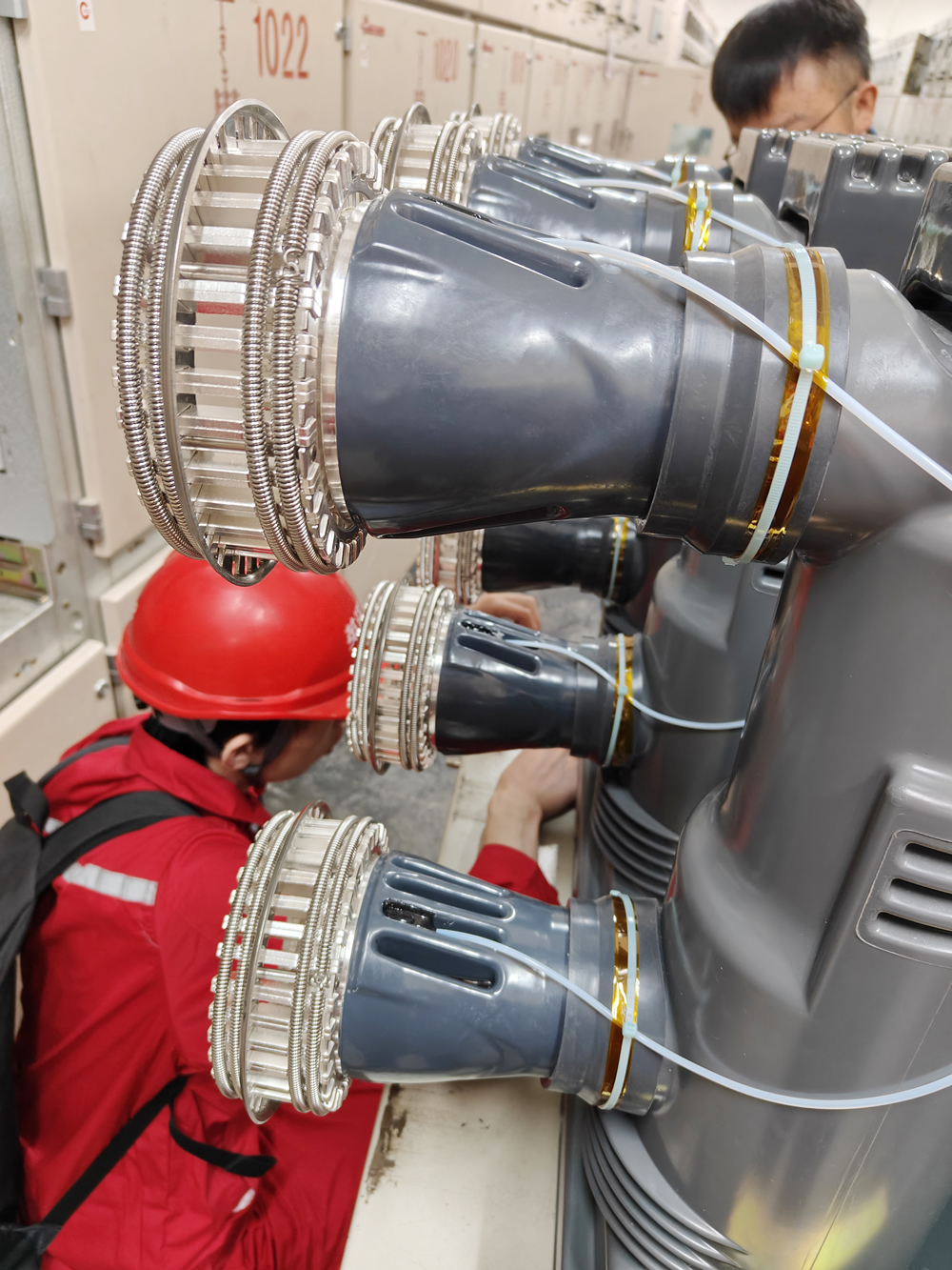
Traditional circuit breaker maintenance follows time-based or operation-count-based schedules: breakers are inspected or overhauled after a fixed number of years or switching operations, regardless of actual condition. While this approach provides a baseline level of reliability, it has fundamental limitations that make it inadequate for modern grid requirements.
The first limitation is the inability to detect inter-maintenance degradation. Faults such as contact erosion, insulation deterioration, and gas leaks develop progressively between scheduled inspections. A breaker may pass inspection and begin degrading the following day, with the fault remaining invisible until the next scheduled outage — which could be years away. During this interval, the breaker continues to serve as a critical protection device while harboring a latent defect that could cause it to fail precisely when it is needed most.
The second limitation is the cost and operational disruption of offline inspection. Inspecting a high-voltage circuit breaker requires taking it out of service, which may require complex switching procedures, load transfers, and coordination with system operators. For critical breakers that cannot be easily de-energized, inspection opportunities are infrequent and brief. Real-time online monitoring eliminates this constraint by providing continuous condition assessment without removing the breaker from service.
The third limitation is the absence of trend data. A single-point inspection reveals the breaker’s condition at one moment in time but provides no information about the rate or direction of change. Real-time monitoring generates continuous time-series data that reveals whether a parameter is stable, improving, or deteriorating — and at what rate. This trend information is essential for predicting remaining useful life and scheduling maintenance with precision.
The economic argument is equally compelling. Unplanned circuit breaker failures result in direct costs (equipment replacement, emergency repair labor, and energy not supplied) and indirect costs (contractual penalties, regulatory scrutiny, and reputational damage). Industry data indicates that the cost of a single unexpected breaker failure in a transmission substation can exceed the cost of monitoring the entire breaker population in that substation for a decade. Real-time circuit breaker monitoring transforms maintenance from a reactive expense into a predictive investment.
3. What Are the Common Fault Types in Circuit Breakers?
Understanding the specific failure mechanisms that affect circuit breakers is essential for designing an effective monitoring strategy. Circuit breaker faults can be categorized into five primary types, each with distinct physical causes, progression characteristics, and monitoring signatures.
1、Thermal Overload and Contact Overheating
As a circuit breaker ages and accumulates switching operations, the contact surfaces degrade through erosion, pitting, and oxidation. This degradation increases the contact resistance, which in turn causes localized resistive heating (P = I²R). The resulting temperature rise accelerates further oxidation and material loss, creating a positive feedback loop. If undetected, thermal overload progresses to contact welding, insulation damage, and ultimately flashover or fire. Temperature monitoring is the most direct method of detecting this fault type, as the temperature rise is measurable before any other symptom becomes apparent.
2、Contact Erosion and Wear
Every interruption of load current or fault current causes arc erosion of the breaker’s contacts. The arc generated during current interruption vaporizes contact material, progressively reducing the contact mass and altering the contact geometry. As contacts erode, the effective contact area decreases, contact pressure distribution becomes uneven, and contact resistance increases. In SF₆ breakers, severe contact erosion can also generate metallic particles that contaminate the gas and compromise its dielectric strength. Monitoring contact temperature, mechanical travel characteristics, and switching operation counts provides insight into the progression of contact wear.
3、Insulation Degradation and Partial Discharge
Circuit breakers contain various solid and gas insulation systems that can degrade over time due to thermal stress, electrical stress, moisture ingress, and chemical contamination. As insulation deteriorates, partial discharge (PD) activity increases — small electrical discharges that occur within voids, along surfaces, or at interfaces where the electric field exceeds the local breakdown strength. PD activity further erodes the insulation, creating a progressive failure path that can eventually lead to complete dielectric breakdown. Partial discharge monitoring detects this degradation at an early stage, while temperature monitoring identifies the thermal consequences of insulation failure.
4、SF₆ Gas Leakage and Contamination
SF₆ gas circuit breakers rely on the dielectric and arc-quenching properties of sulfur hexafluoride gas. Gas leakage through aging seals, gaskets, or weld defects reduces the gas density below the level required for reliable arc interruption and insulation. Additionally, moisture ingress into the SF₆ compartment, or contamination from arc byproducts and metallic particles, degrades the gas quality even if the density remains adequate. Gas density monitoring and moisture analysis are essential for detecting these faults, while temperature monitoring provides complementary information about the thermal effects of reduced gas performance.
5、Mechanical Failure and Operating Mechanism Defects
The mechanical operating mechanism of a circuit breaker — whether spring-operated, hydraulic, or pneumatic — must reliably store and release energy to open and close the breaker within specified time limits. Mechanical failures include linkage wear, spring fatigue, damper deterioration, latch malfunction, and lubrication degradation. These faults manifest as changes in operating time (slow operation), incomplete travel, or failure to operate. Mechanical condition monitoring typically involves timing analysis, travel measurement, coil current analysis, and vibration monitoring. Temperature monitoring of mechanism components can also reveal abnormal friction or bearing degradation.
These five fault categories are not independent. In practice, faults often interact and cascade: contact erosion leads to increased temperature, which accelerates insulation degradation, which increases partial discharge, which further degrades insulation. A comprehensive circuit breaker monitoring system tracks multiple parameters simultaneously to capture these interactions and provide a holistic assessment of breaker health.
4. What Are the Key Monitoring Parameters for Circuit Breakers?
An effective circuit breaker monitoring system tracks a range of parameters that collectively characterize the breaker’s electrical, thermal, dielectric, and mechanical condition. The selection and prioritization of these parameters depend on the breaker type, voltage class, criticality, and the specific failure modes most relevant to the application. The following parameters form the foundation of a comprehensive circuit breaker monitoring strategy.
Temperature
Temperature is the most fundamental and universally applicable monitoring parameter for circuit breakers. It provides direct indication of contact resistance changes, thermal overload conditions, abnormal current distribution, and insulation thermal aging. Temperature monitoring points include the stationary contacts, moving contacts, busbar connection joints, cable terminations, and arc chamber components. Fiber optic temperature sensors are the preferred technology for this application due to their immunity to electromagnetic interference and inherent electrical isolation.
Partial Discharge (PD)
Partial discharge monitoring detects incipient insulation degradation by measuring the small electrical discharges that occur when insulation begins to fail. PD activity is measured using ultra-high-frequency (UHF) sensors, transient earth voltage (TEV) sensors, or acoustic emission sensors. PD data provides early warning of dielectric failures that, if left unaddressed, can progress to complete insulation breakdown and flashover.
SF₆ Gas Density and Moisture
For SF₆ circuit breakers, gas density is a critical safety parameter. The breaker’s arc interruption capability and dielectric withstand strength are directly proportional to the SF₆ gas density. Density sensors compensate for temperature variations to provide true mass-density readings. Moisture content monitoring is equally important, as excessive moisture degrades the gas’s dielectric properties and produces corrosive byproducts that attack internal components.
Mechanical Operating Characteristics
Mechanical monitoring encompasses operating time measurement (close time, open time, close-open time), contact travel analysis, operating coil current signature analysis, and motor current monitoring. These measurements reveal the condition of the operating mechanism, linkage system, dampers, and energy storage components. Changes in timing or travel characteristics indicate developing mechanical faults that could result in slow operation or failure to operate.
Load Current
Continuous load current measurement serves two purposes in circuit breaker monitoring. First, it provides the baseline for correlating temperature measurements with actual loading conditions — enabling the system to distinguish between normal temperature rise due to high load and abnormal temperature rise due to contact degradation. Second, it tracks cumulative current loading and switching duty, which are key inputs for estimating remaining contact life and scheduling maintenance.
Busbar and Connection Status
Monitoring the condition of busbar connections and cable terminations at the breaker terminals is essential because these joints are common failure points. Loose or corroded connections increase resistance, generate heat, and can lead to thermal failure. Temperature monitoring at these points, combined with load current data, provides effective detection of deteriorating connections.
Among all monitoring parameters, temperature is the one that provides the earliest indication of the widest range of fault types. Contact overheating, connection degradation, insulation thermal aging, and mechanical friction all produce measurable temperature signatures before other symptoms appear. This is why FJINNO’s circuit breaker monitoring strategy prioritizes high-accuracy fiber optic temperature measurement as the foundation upon which other monitoring parameters are layered.
5. Why Is Temperature the Most Critical Early Warning Indicator for Circuit Breakers?

While circuit breaker monitoring encompasses multiple parameters, temperature occupies a unique and central position in the monitoring hierarchy. This is not arbitrary — it is grounded in the physics of circuit breaker degradation and the practical requirements of early fault detection.
The relationship between contact degradation and temperature is governed by a straightforward physical principle. When a circuit breaker’s contacts degrade — through erosion, oxidation, carbon buildup, or mechanical misalignment — the electrical contact resistance increases. Because the breaker continuously carries load current, any increase in contact resistance directly increases the power dissipated as heat at the contact interface, following the relationship P = I²R. This localized heating raises the contact temperature above its normal operating baseline. The temperature rise is proportional to the increase in contact resistance, making it a quantitative indicator of degradation severity.
What makes temperature particularly valuable as an early warning indicator is the temporal relationship between temperature change and other fault manifestations. In most degradation scenarios, the temperature at the affected component begins to rise measurably weeks or months before other symptoms — such as increased partial discharge, gas decomposition products, or mechanical changes — become detectable. This is because the thermal effect is a first-order consequence of resistance increase, while other effects are secondary or tertiary consequences that require further degradation progression to become measurable.
Consider the degradation sequence for a typical contact overheating fault. As contact resistance increases, the local temperature rises. This elevated temperature accelerates oxidation of the contact surfaces, which further increases resistance — creating the positive feedback loop described earlier. As the temperature continues to rise, the insulation adjacent to the hot contact begins to thermally age, which may eventually produce partial discharge activity. If the breaker uses SF₆, the elevated temperature can accelerate gas decomposition and moisture generation. Finally, if the mechanical components are affected by the heat, operating characteristics may change. Throughout this sequence, the temperature rise is the first measurable symptom and remains the most sensitive indicator of fault severity.
There is also a practical advantage to temperature monitoring: it is directly interpretable. A measured temperature of 105°C at a contact rated for 90°C immediately communicates the severity and urgency of the situation. Other parameters — such as partial discharge magnitude in picocoulombs or gas moisture content in ppm — require expert interpretation and contextual analysis. Temperature, by contrast, can be evaluated against absolute thresholds defined in standards such as IEC 62271 and IEEE C37, making alarm setting and response decision-making straightforward.
6. Why Is Fiber Optic Technology Best Suited for Circuit Breaker Temperature Monitoring?
The internal environment of a circuit breaker presents extreme challenges for temperature measurement. High voltage potentials, intense electromagnetic fields during switching operations, confined spaces, and the need for long-term unattended operation eliminate most conventional temperature sensing technologies from consideration. Fiber optic temperature sensing — specifically fluorescent fiber optic sensing — addresses every one of these challenges simultaneously.
Optical fibers carry light, not electrical signals. Electromagnetic interference from switching arcs, bus currents, and adjacent equipment has zero effect on the measurement signal, eliminating the noise and error problems that plague electronic sensors in breaker environments.
Fiber optic sensors are fully dielectric — no conductive path exists between the high-voltage contact being measured and the grounded monitoring equipment. This eliminates the need for complex insulation barriers and provides natural galvanic isolation at any voltage level.
Fluorescent fiber optic sensors contain no active electronic components, batteries, or moving parts. The measurement principle is based on the temperature-dependent decay time of a phosphor material — an intrinsic physical property that does not drift or degrade. No periodic recalibration is required.
The sensing element is typically a few millimeters in diameter, small enough to be mounted directly on contacts, busbars, and arc chamber components in the confined spaces inside a circuit breaker without obstructing operation or gas flow.
Fiber optic sensor materials are compatible with SF₆ gas, insulating oils, and the arc byproducts present inside circuit breakers. They do not outgas, corrode, or contaminate the breaker’s internal environment.
The fluorescence decay-time measurement principle provides inherent long-term stability because it depends on an intrinsic material property rather than signal amplitude. Sensor readings remain accurate over decades of continuous operation without drift.
Conventional alternatives — thermocouples, RTDs, and infrared sensors — each fail in one or more of these critical requirements. Thermocouples and RTDs introduce conductive elements into the high-voltage environment, creating insulation risks and EMI susceptibility. Infrared sensors require a line of sight to the target surface, which is typically unavailable inside an enclosed breaker. Wireless electronic sensors require batteries (which have limited life and are unsuitable for sealed SF₆ compartments) and remain susceptible to EMI during breaker operations. Fluorescent fiber optic sensing is the only technology that satisfies all requirements simultaneously, which is why it has become the standard for high-voltage circuit breaker temperature monitoring.
FJINNO’s fluorescent fiber optic temperature sensors are specifically engineered for circuit breaker applications. With ±1°C accuracy, response time under 2 seconds, and a measurement range of -40°C to +200°C, they provide the precision and reliability required for early detection of contact overheating and thermal anomalies in SF₆, vacuum, and oil circuit breakers.
7. What Are the Components of a Circuit Breaker Fiber Optic Temperature Monitoring System?
A complete fiber optic temperature monitoring system for circuit breakers consists of three functional layers: the sensing layer, the signal processing layer, and the data management and integration layer. Each layer performs a distinct function, and together they form an end-to-end monitoring architecture that transforms physical temperature at the breaker’s critical points into actionable information in the operator’s control system.
Fluorescent fiber optic temperature sensors installed on contacts, busbars, arc chambers, and cable terminations. Convert local temperature into an optical signal.
➔📡Layer 2: Signal Processing
Fiber optic signal demodulator (edge device) receives optical signals, extracts temperature data, performs threshold comparison, and generates local alarms.
➔🖥️Layer 3: Data Management
SCADA / DCS / asset management software receives temperature data via Modbus, IEC 61850, or DNP3.0 for centralized display, trending, and diagnostics.
Layer 1 — Fluorescent Fiber Optic Temperature Sensors
The sensing layer consists of fluorescent fiber optic temperature probes installed at each monitoring point within the circuit breaker. Each probe contains a phosphor sensing element bonded to the tip of an optical fiber. When excited by a pulse of light from the demodulator, the phosphor fluoresces, and the decay time of this fluorescence is a precise function of the local temperature. The probe is connected to the demodulator via an optical fiber cable that provides both the excitation light path and the return fluorescence signal path. Because the fiber is entirely dielectric, it can safely route from the high-voltage contact through the breaker’s insulation system to the grounded demodulator without compromising the breaker’s dielectric integrity. FJINNO sensors feature a compact probe design that allows direct mounting on stationary contacts, moving contact arms, busbar clamps, and arc chamber walls using high-temperature adhesive or mechanical fixation.
Layer 2 — Fiber Optic Signal Demodulator (Edge Device)
The signal processing layer is the fiber optic demodulator unit, which serves as the intelligent edge device of the monitoring system. The demodulator performs several critical functions: it generates the optical excitation pulses sent to each sensor, receives the returning fluorescence signals, applies the decay-time measurement algorithm to calculate temperature for each channel, compares the measured temperatures against configurable alarm thresholds, and outputs the processed data to the supervisory layer. FJINNO demodulators support multi-channel configurations (4, 8, 16, or 24 channels) to accommodate different breaker configurations and can simultaneously monitor all three phases plus busbar and mechanism points from a single unit. The demodulator includes local display, relay alarm outputs, and digital communication interfaces including Modbus RTU/TCP, IEC 61850 MMS and GOOSE, and DNP3.0.
Layer 3 — Supervisory Software and SCADA Integration
The data management layer receives temperature data from the demodulator and presents it within the utility’s or industrial facility’s existing supervisory control system. Integration is achieved through standard communication protocols, allowing the temperature data to appear alongside other breaker monitoring parameters, protection system data, and operational data in the control room. Advanced implementations include trend analysis, rate-of-change alarms, thermal modeling, and predictive diagnostics that combine temperature data with load current and ambient temperature to assess the breaker’s thermal health trajectory. FJINNO provides optional companion software for standalone monitoring applications where SCADA integration is not required, offering dashboard visualization, alarm management, historical data storage, and report generation.
8. Where and How Should Temperature Sensors Be Deployed in Circuit Breakers?
The effectiveness of a circuit breaker temperature monitoring system depends critically on the placement of temperature sensors at the locations where thermal faults originate and develop. Sensor placement must be guided by an understanding of the breaker’s internal thermal architecture and the specific failure modes being targeted. The following table identifies the critical monitoring points, the fault types each location addresses, and the deployment considerations for each.
| Monitoring Location | Target Fault Type | Deployment Notes |
|---|---|---|
| Stationary Contacts (Fixed Contacts) | Contact resistance increase, contact erosion, carbon buildup | Sensor mounted on the contact finger assembly or contact support structure as close to the current-carrying interface as the design permits. This is the single most important monitoring point in any circuit breaker. |
| Moving Contacts (Mobile Contacts) | Contact misalignment, uneven wear, mechanical binding | Sensor mounted on the moving contact arm or tulip assembly. Fiber routing must accommodate the contact travel stroke without mechanical stress on the fiber. FJINNO sensors use flexible fiber leads designed for this application. |
| Arc Chamber / Interrupter | Arc erosion accumulation, nozzle degradation, dielectric weakening | Sensor installed on the arc chamber wall or nozzle support structure. Monitors the thermal condition of the interrupting assembly, which is subject to extreme thermal stress during fault current interruption. |
| Busbar Connection Joints | Connection loosening, corrosion, plating degradation | Sensor mounted directly on the bolted or clamped busbar connection at each phase terminal. These joints are common failure points due to thermal cycling and mechanical vibration over time. |
| Cable Terminations | Termination degradation, crimp loosening, insulation aging | Sensor mounted at the cable-to-breaker interface. Particularly important for breakers connected via XLPE or oil-filled cable systems where termination quality is critical. |
| Operating Mechanism Components | Bearing wear, lubrication degradation, abnormal friction | Sensor mounted on mechanism housing or bearing points. Provides supplementary information on mechanical health by detecting abnormal heat generation from friction or failed lubrication. |
For a typical three-phase circuit breaker installation, the minimum recommended sensor deployment consists of one sensor per phase on the stationary contacts and one sensor per phase on the busbar connections — six sensors total. A comprehensive deployment adds sensors on the moving contacts, arc chambers, and cable terminations, bringing the total to 12–18 sensors per breaker. FJINNO multi-channel demodulators are configured to support these deployment densities, with 16-channel and 24-channel models accommodating full monitoring of a single breaker or partial monitoring of multiple breakers from a single unit.
9. FJINNO Fluorescent Fiber Optic Temperature Monitoring System — Technical Specifications
The following specifications describe FJINNO’s fluorescent fiber optic temperature monitoring system as configured for circuit breaker applications. The system consists of the fluorescent fiber optic temperature sensor probes and the multi-channel signal demodulator. All specifications are validated under the operating conditions typical of high-voltage circuit breaker environments.
Fluorescent Fiber Optic Temperature Sensor
| Parameter | Specification |
|---|---|
| Measurement Principle | Fluorescence decay time |
| Measurement Range | -40°C to +200°C (extended range available to +300°C) |
| Accuracy | ±1°C (over full range) |
| Resolution | 0.1°C |
| Response Time | < 2 seconds |
| Sensor Probe Diameter | ≤ 3 mm |
| Fiber Cable Length | Up to 100 m (standard); extended lengths on request |
| Dielectric Withstand | Complete electrical isolation (all-dielectric construction) |
| EMI Immunity | Fully immune — no electromagnetic interference susceptibility |
| Chemical Compatibility | Compatible with SF₆, mineral oil, silicone oil, dry air |
| Service Life | > 20 years (no recalibration required) |
Multi-Channel Fiber Optic Signal Demodulator
| Parameter | Specification |
|---|---|
| Channel Options | 4 / 8 / 16 / 24 channels |
| Sampling Rate | 1 sample per second per channel |
| Communication Protocols | Modbus RTU, Modbus TCP, IEC 61850 (MMS & GOOSE), DNP3.0 |
| Alarm Outputs | Configurable relay contacts (2-stage or 4-stage alarm) |
| Display | Local LCD display with channel-by-channel readout |
| Data Storage | Internal memory for historical data logging |
| Operating Temperature | -40°C to +70°C |
| Power Supply | 85–265 V AC or 110/220 V DC (wide-range input) |
| Protection Rating | IP65 (outdoor installation capable) |
| Mounting | DIN rail, panel mount, or wall mount |
10. How Do Monitoring Strategies Differ Across Circuit Breaker Types?

Circuit breakers are manufactured in diverse configurations, each with distinct insulating media, interrupting principles, and construction designs. While the core monitoring objective — early detection of developing faults — remains constant, the specific monitoring strategy must be adapted to the characteristics and dominant failure modes of each breaker type.
SF₆ Gas Circuit Breakers
SF₆ breakers are the most widely deployed type in high-voltage transmission systems (72.5 kV and above). Their primary monitoring requirements include contact temperature monitoring (to detect contact degradation and resistance increase), SF₆ gas density monitoring (to detect leakage and ensure adequate arc-quenching capability), gas moisture content monitoring (to prevent corrosive byproduct formation), and partial discharge monitoring (to detect insulation degradation). The sealed gas compartment makes fiber optic temperature sensors particularly valuable, as they can be installed inside the sealed compartment without penetrating the gas boundary or introducing leak paths. FJINNO sensors are fully compatible with SF₆ gas and do not produce outgassing or contamination.
Vacuum Circuit Breakers
Vacuum breakers are predominant in medium-voltage distribution systems (1 kV to 40.5 kV). Their primary monitoring focus is contact erosion (tracked through switching operation counts and contact temperature), vacuum integrity (loss of vacuum results in failure to interrupt), and operating mechanism condition. Because the vacuum interrupter is a sealed unit, direct contact temperature measurement typically requires sensors on the external connections or the upper and lower terminals of the vacuum bottle. The temperature differential between the upper and lower terminals provides an indirect indicator of internal contact condition. FJINNO’s compact fiber optic sensors can be mounted at these terminal points to provide continuous thermal monitoring.
Oil Circuit Breakers
Oil circuit breakers use mineral oil as both the insulating medium and the arc-quenching medium. While largely superseded by SF₆ and vacuum technology in new installations, large numbers of oil breakers remain in service worldwide. Their monitoring requirements include contact temperature (monitored through fiber optic sensors positioned at the contact supports above the oil level), oil quality analysis (dielectric strength, moisture, dissolved gas), and mechanical operating characteristics. Temperature monitoring is particularly important because oil circuit breakers are susceptible to carbonization of the oil near overheating contacts, which degrades the oil’s insulating and arc-quenching properties.
Dead-Tank Circuit Breakers
Dead-tank breakers house the interrupters inside a grounded metal tank, which is common in North American utility practice. The grounded tank provides natural shielding but also makes internal access for inspection difficult. Monitoring points include the bushing current connections (where current transfers from the external buswork through bushings into the tank), the internal interrupter contacts, and the operating mechanism. Fiber optic sensors can be routed through the bushing or through dedicated fiber feedthroughs in the tank wall to reach internal monitoring points. FJINNO provides application-specific fiber routing solutions for dead-tank configurations.
Live-Tank Circuit Breakers
Live-tank breakers mount the interrupters on insulating columns at line potential, typical in European and Asian transmission practice. The interrupters are exposed to ambient weather conditions, and the high-voltage location of the interrupters means that all sensor connections must be fully insulated from ground. Fiber optic sensors are inherently suited to this configuration because the optical fiber provides the required insulation while routing the temperature signal from the live interrupter down to the grounded monitoring equipment. FJINNO systems for live-tank breakers include UV-resistant fiber cables and weatherproof sensor enclosures for outdoor installation.
Independent Pole Operated Breakers (IPOB) vs. Gang Operated Breakers (GOB)
Independent pole operated breakers have a separate operating mechanism for each phase, allowing individual phase control. Gang operated breakers use a single mechanism to operate all three phases simultaneously. From a monitoring perspective, IPOBs require per-phase timing and mechanical analysis to detect individual mechanism faults, while GOBs require monitoring of the common mechanism plus inter-phase synchronization. Temperature monitoring requirements are similar for both types — each phase’s contacts and connections must be individually monitored regardless of the operating mechanism arrangement.
11. Frequently Asked Questions (FAQ)
What is a circuit breaker monitoring system?
A circuit breaker monitoring system is a real-time condition monitoring solution that continuously tracks critical parameters such as temperature, partial discharge, SF₆ gas density, mechanical operating characteristics, and load current. By analyzing these parameters, the system detects early-stage faults and provides actionable alerts that enable condition-based maintenance, preventing unexpected failures and extending breaker service life.
Why is temperature the most important parameter in circuit breaker monitoring?
Temperature is the earliest and most direct indicator of contact degradation, increased contact resistance, and thermal overload. When contact resistance increases due to erosion, oxidation, or loosening, the resulting power dissipation (P = I²R) causes a measurable temperature rise at the contact. This temperature change is typically detectable weeks or months before other fault symptoms appear, making it the most valuable early warning parameter for preventing catastrophic failures in circuit breakers.
Why is fiber optic temperature sensing preferred for circuit breaker monitoring?
Fiber optic sensors are inherently immune to electromagnetic interference (EMI), provide complete electrical isolation, require no calibration or maintenance, and offer long-term measurement stability. These properties make them uniquely suited for the high-voltage, high-EMI environment inside circuit breakers, where conventional electronic sensors such as thermocouples, RTDs, and wireless sensors cannot operate reliably. Fluorescent fiber optic sensing is the only technology that satisfies all of these requirements simultaneously.
What types of circuit breakers can be monitored with fiber optic temperature sensors?
Fiber optic temperature sensors can be deployed in all major circuit breaker types, including SF₆ gas circuit breakers, vacuum circuit breakers, oil circuit breakers, and both live-tank and dead-tank configurations. The sensor’s compact size (≤ 3 mm diameter), full dielectric construction, and chemical compatibility with SF₆ and insulating oil allow installation directly on contacts, busbars, and arc chambers inside the breaker.
Where should temperature sensors be installed in a circuit breaker?
The critical temperature monitoring points in a circuit breaker are the stationary contacts, moving contacts, arc chambers, busbar connection joints, cable terminations, and operating mechanism components. For a minimum deployment, sensors should be placed on the stationary contacts and busbar connections of each phase (six sensors total). A comprehensive deployment adds moving contacts, arc chambers, and cable terminations, bringing the total to 12–18 sensors per breaker.
Can fiber optic sensors be retrofitted into existing circuit breakers?
Yes. FJINNO fluorescent fiber optic temperature sensors are designed for both new installations and retrofit applications. The compact probe design and flexible fiber cable allow installation during scheduled maintenance outages without structural modifications to the breaker. For SF₆ breakers, sensors can be installed during a gas-down maintenance event and do not require permanent gas boundary penetrations. For vacuum and oil breakers, sensors are typically installed at the external terminal connections.
What is the measurement accuracy of FJINNO fiber optic temperature sensors?
FJINNO fluorescent fiber optic temperature sensors provide a measurement accuracy of ±1°C across the full operating range of -40°C to +200°C, with a resolution of 0.1°C and a response time of less than 2 seconds. The measurement principle (fluorescence decay time) is inherently stable and does not drift over time, so no periodic recalibration is required. The specified accuracy is maintained over the entire sensor service life of more than 20 years.
How does the monitoring system integrate with existing SCADA systems?
FJINNO fiber optic signal demodulators support standard industrial communication protocols including Modbus RTU, Modbus TCP, IEC 61850 (MMS and GOOSE), and DNP3.0. These protocols enable seamless integration with existing SCADA, DCS, or dedicated asset management platforms. The demodulator outputs processed temperature data for each channel, along with alarm status, through the selected protocol. For facilities without SCADA, FJINNO provides optional standalone monitoring software with dashboard visualization, alarm management, and historical trending.
Protect Your Circuit Breakers with FJINNO Fiber Optic Temperature Monitoring
Get real-time visibility into contact temperature, connection health, and thermal anomalies with our fluorescent fiber optic monitoring system — designed for SF₆, vacuum, and oil circuit breakers.
Disclaimer: The information provided on this page is for general informational and educational purposes only. FJINNO makes every effort to ensure the accuracy and completeness of the information presented, but does not guarantee that it is free from errors. Product specifications are subject to change without notice. The mention of third-party companies, products, or trade names is for reference purposes only and does not imply endorsement or affiliation. All trademarks and trade names mentioned are the property of their respective owners. For the latest product specifications and application guidance, please contact FJINNO directly.

Fiber optic temperature sensor, Intelligent monitoring system, Distributed fiber optic manufacturer in China
 |
 |
 |