 INNO fibre optic temperature sensors ,temperature monitoring systems.
- Arc Detection (Arc Detect) is a real-time protection technology that identifies arc flash events inside medium voltage switchgear, busbars, and distribution panels within 1–10 ms by sensing the intense light emitted during arcing.
- Unlike conventional overcurrent relays that wait for current to exceed a set threshold, an arc detection system responds to optical signals — dramatically reducing arc flash energy release and the risk of personnel injury or equipment destruction.
- Available in three main sensor configurations: point-type fibre optic sensors, loop-type fibre optic sensors, and photoelectric sensors — each suited to different switchgear layouts and retrofit constraints.
- Installed inside busbar compartments, circuit breaker chambers, and cable termination chambers of medium voltage switchgear panels, with current-check logic to prevent false tripping.
- Arc detection relays communicate via IEC 61850 GOOSE, Modbus RTU, or hardwired output for direct tripping of upstream circuit breakers, achieving system-level fault clearance in under 10 ms.
- This guide covers working principle, sensor types, key specifications, installation locations, comparison with overcurrent protection, multi-sensor system integration, selection criteria, and 10 frequently asked questions.
Table of Contents
- What Is Arc Detection (Arc Detect) and Why Is It Critical for Electrical Safety?
- How Does Arc Flash Occur? Causes, Energy Release, and Hazard Levels
- How Does an Arc Detection System Work? From Light Signal to Breaker Trip
- Arc Detection vs Conventional Overcurrent Protection: Key Differences
- Arc Detection Sensor Types: Point, Loop, and Photoelectric Compared
- Key Specifications: How to Read an Arc Detection System Datasheet?
- Where Is Arc Detection Installed in Medium Voltage Switchgear?
- Arc Detection Combined with Partial Discharge and Temperature Monitoring
- Arc Detection System Communication and Trip Integration: IEC 61850 and Modbus
- How to Select the Right Arc Detection System for Your Project?
- Common Installation Mistakes and How to Avoid Them
- Frequently Asked Questions (FAQ)
1. What Is Arc Detection (Arc Detect) and Why Is It Critical for Electrical Safety?
E-mail: web@fjinno.net
WhatsApp: +8613599070393
Arc Detection, often referred to as arc detect or arc flash detection, is a specialist protection technology designed to identify the occurrence of an internal arc fault — a violent, uncontrolled electrical discharge — inside enclosed electrical equipment such as medium voltage switchgear panels, ring main units (RMUs), motor control centres (MCCs), and distribution boards. When an arc flash event occurs, it releases an enormous burst of thermal energy, intense light, pressure waves, and molten metal. Without rapid detection and fault clearance, the consequences range from total equipment destruction to fatal injury for personnel working in the vicinity.
The defining characteristic of an arc detection system is speed. A conventional overcurrent relay must detect that fault current has exceeded a preset threshold — a process that takes 60 ms to several hundred milliseconds depending on relay grading requirements. In that time, a high-current arc flash can release tens of kilojoules of energy, enough to cause severe burns at distances of several metres. An arc detection relay, by contrast, responds to the intense optical flash produced at the instant the arc forms. This light-based detection mechanism allows fault clearance in 1–10 ms — a reduction of one to two orders of magnitude compared with overcurrent-only protection.
For utility companies, industrial plant operators, data centre owners, and rail infrastructure engineers, arc detect technology is a foundational element of arc flash risk management programmes. It directly reduces the Incident Energy available at the fault point, enabling compliance with IEEE 1584 arc flash hazard calculations and supporting the reduction of personal protective equipment (PPE) requirements for switchgear operators.
Who Uses Arc Detection Systems?
Arc detection is widely deployed in medium voltage switchgear operating at 6.6 kV, 10 kV, 11 kV, 22 kV, 33 kV, and 35 kV. Typical users include power generation facilities, oil and gas plants, mining operations, water treatment works, large commercial and industrial campuses, and original equipment manufacturers (OEMs) of switchgear panels. The technology is increasingly specified as a standard feature in new switchgear procurement contracts across Europe, North America, and Asia Pacific.
2. How Does Arc Flash Occur? Causes, Energy Release, and Hazard Levels
An arc flash inside a switchgear panel occurs when electrical current flows through ionised air or contaminated insulation between conductors at different potentials. Once the arc is established, it is self-sustaining: the plasma column generated by the arc further ionises the surrounding atmosphere, reducing its resistance and allowing ever-increasing current to flow. The result is an exponential build-up of energy that terminates only when the fault is cleared by a protective device or when the available fault current collapses.
Common Root Causes of Arc Flash Events
The most frequent triggers for internal arc faults in medium voltage switchgear are insulation degradation caused by partial discharge activity, contamination of insulating surfaces by dust, moisture, or conductive particles, small animal ingress (rodents, insects) that bridge phase-to-earth clearances, incorrect switching operations or maintenance errors, and mechanical failure of busbar support insulators or contact assemblies. Understanding these root causes reinforces why arc detection must be deployed alongside insulation monitoring technologies rather than in isolation.
Arc Flash Energy and Hazard Categories (IEEE 1584)
The severity of an arc flash event is quantified as Incident Energy, expressed in calories per square centimetre (cal/cm²), calculated at a standardised working distance from the arc source. IEEE 1584 defines the methodology for this calculation, taking into account fault current magnitude, system voltage, gap between conductors, and — critically — the fault clearance time. Because arc detection reduces clearance time from hundreds of milliseconds to single-digit milliseconds, it produces a dramatic reduction in calculated Incident Energy and may lower the required PPE category by two or more levels.
| PPE Category | Incident Energy Range (cal/cm²) | Minimum Arc Rating | Typical Protection Level |
|---|---|---|---|
| Category 1 | 1.2 – 4 | 4 cal/cm² | Arc-rated shirt and trousers |
| Category 2 | 4 – 8 | 8 cal/cm² | Arc-rated jacket and face shield |
| Category 3 | 8 – 25 | 25 cal/cm² | Arc-rated suit, balaclava, hard hat |
| Category 4 | 25 – 40 | 40 cal/cm² | Full arc flash suit system |
3. How Does an Arc Detection System Work? From Light Signal to Breaker Trip
Optical Detection Principle
An arc flash produces a luminous intensity many orders of magnitude greater than ambient switchgear lighting. Arc detection sensors exploit this characteristic by continuously monitoring light levels inside switchgear compartments. When the sensor detects a sudden, sharp rise in luminosity that exceeds a configurable threshold, it signals the arc detection relay. The relay then applies a current-check logic before issuing a trip command, ensuring that the optical trigger is accompanied by a measurable increase in fault current — a dual-criterion approach that eliminates false tripping caused by inadvertent light sources such as torch beams or camera flashes.
Dual-Criterion Logic: Light Plus Current Confirmation
The arc detection relay receives two simultaneous inputs: an optical signal from the arc sensor and a current magnitude signal from the existing protection current transformers (CTs). A trip command is only issued when both conditions are met within a short time window — typically less than 1 ms. This dual-criterion logic provides a critical balance between response speed and selectivity, ensuring the system does not inadvertently trip on non-fault optical events while still responding to a genuine arc flash in under 10 ms from fault inception to circuit breaker trip coil energisation.
System Response Chain
The complete arc detection response chain operates as follows: the arc forms and emits light (t = 0 ms); the fibre optic or photoelectric sensor detects the optical flash (t ≈ 0.1–0.5 ms); the arc detection relay confirms the concurrent current rise and issues a trip command (t ≈ 1–2 ms); the trip signal is transmitted to the upstream circuit breaker via hardwired output, IEC 61850 GOOSE message, or a dedicated trip bus (t ≈ 2–4 ms); the circuit breaker interrupts fault current (t ≈ 6–10 ms total from arc inception). Compared with a conventional overcurrent relay operating at minimum 60 ms, this represents a reduction in arc flash energy of approximately 80–95%.
4. Arc Detection vs Conventional Overcurrent Protection: Key Differences
Many electrical engineers encountering arc detection for the first time ask how it differs from the overcurrent and earth fault protection already built into every protection relay. The comparison below clarifies the fundamental distinctions.
| Parameter | Conventional Overcurrent Protection | Arc Detection System |
|---|---|---|
| Detection Principle | Current exceeds set threshold | Optical flash + current confirmation |
| Response Time | 60 ms – 500 ms (relay grading dependent) | 1 – 10 ms (from arc inception to trip) |
| Arc Flash Energy Released | High (proportional to clearance time) | Extremely low (80–95% reduction) |
| Primary Measurand | Fault current magnitude | Light intensity inside compartment |
| False Trip Risk | Low (current-based, selective) | Low (dual-criterion light + current logic) |
| Installation Location | Protection CT on primary conductor | Sensor inside switchgear compartment |
| Compliant With | IEC 60255, IEEE C37.112 | IEC 62271-200, IEEE 1584 |
| Can Replace Each Other? | No — they are complementary layers of protection | |
Arc detection does not replace overcurrent protection — it operates as an additional, faster-acting protective layer. In a correctly designed protection scheme, the arc detection relay issues an instantaneous trip while the overcurrent relay provides backup protection for faults outside the arc detection zone, such as downstream feeder faults.
5. Arc Detection Sensor Types: Point, Loop, and Photoelectric Compared
Point-Type Fibre Optic Sensor — Targeted Coverage
A point-type fibre optic arc detection sensor uses a short section of optical fibre terminated with a light-collecting lens or bare fibre end. It is installed at a fixed point inside a specific switchgear compartment and detects arc flash light within its field of view. Point sensors are the simplest and most cost-effective option and are well suited to switchgear with clearly defined, compact compartments. Multiple point sensors are connected to a single arc detection relay, with each sensor assigned to a specific protection zone.
Loop-Type Fibre Optic Sensor — Wide Area Coverage
A loop-type fibre optic arc detection sensor consists of a continuous optical fibre loop routed around the perimeter of a switchgear compartment or along an entire switchboard. The entire length of the fibre acts as a distributed light sensor: any arc flash occurring anywhere along the loop path is detected within milliseconds. Loop sensors provide maximum coverage with a single sensor run, making them ideal for large multi-panel switchboards and busbar tunnels where installing numerous point sensors would be impractical.
Photoelectric Sensor — Compact and Versatile
A photoelectric arc detection sensor uses a solid-state photodiode or phototransistor to detect optical radiation in the visible and near-infrared spectrum. It is typically housed in a small, rugged enclosure and mounted directly inside the switchgear compartment. Photoelectric sensors do not require a separate optical fibre run, which simplifies wiring. However, they are electronic components and must be rated for the harsh electromagnetic environment inside energised switchgear panels.
| Feature | Point Fibre Optic Sensor | Loop Fibre Optic Sensor | Photoelectric Sensor |
|---|---|---|---|
| Coverage Area | Single point / limited FOV | Full perimeter of compartment | Single point / adjustable FOV |
| Installation Complexity | Low | Medium | Low |
| EMI Immunity | Excellent (passive fibre) | Excellent (passive fibre) | Good (electronic shielding required) |
| Retrofit Suitability | High | High | High |
| Best Application | Compact MV panels, specific zones | Large switchboards, busbar tunnels | Compact panels, panel OEM integration |
| Fibre Cable Required? | Yes (short run) | Yes (full loop) | No |
6. Key Specifications: How to Read an Arc Detection System Datasheet?
Response Time
The most critical specification is the total system response time, measured from arc inception to relay output contact closure or GOOSE message transmission. Leading arc detection relays achieve optical detection and current confirmation in under 1 ms, with relay output issued within 2 ms. Always verify that the quoted response time covers the full signal processing chain and not merely the sensor detection latency in isolation.
Optical Sensitivity and Spectral Range
The sensor’s optical sensitivity defines the minimum light intensity it can reliably detect, typically expressed in lux or as a threshold multiplier over ambient light levels. The spectral range — commonly 400 nm to 1100 nm — determines which wavelengths the sensor responds to. Broadband sensors covering both visible and near-infrared ranges provide more robust detection across different arc types than sensors tuned to narrow spectral bands.
Current-Check Threshold and Setting Range
The current-check threshold is the minimum fault current level that must be present simultaneously with the optical signal for a trip command to be issued. This value is configurable and should be set above the maximum load current at the protected point to prevent false tripping under normal operating conditions. Typical setting ranges are 0.1 kA to 20 kA, covering most medium voltage feeder and busbar fault scenarios.
Number of Sensor Inputs and Protection Zones
A single arc detection relay may support 4 to 24 sensor inputs depending on the model, with each input assigned to a discrete protection zone. This allows a single relay to protect all compartments of a multi-feeder switchboard simultaneously, with independent zone identification for fault location and event logging.
Maximum Fibre Length
For fibre optic sensor types, the manufacturer specifies the maximum allowable fibre length between the sensor and the relay. Exceeding this length attenuates the optical signal and may prevent reliable detection. Standard maximum lengths range from 20 m to 100 m depending on the fibre type and relay design.
7. Where Is Arc Detection Installed in Medium Voltage Switchgear?
Busbar Compartment
The busbar compartment houses the main busbars that carry power through the entire switchboard. An arc flash in the busbar compartment has the potential to affect every panel on the board simultaneously. Installing at least one arc detection sensor — preferably a loop-type sensor running the full length of the busbar chamber — in this compartment is considered best practice and is often mandated by utility specifications.
Circuit Breaker Chamber
The circuit breaker (or withdrawable unit) chamber contains the switching device and its associated contacts and insulating components. Mechanical failures or insulation faults at the breaker contacts are a leading cause of arc flash events. A point-type sensor positioned to cover the contact area provides targeted, rapid detection.
Cable Termination Chamber
The cable termination chamber (cable box) is where the incoming or outgoing power cables are terminated. Contamination, moisture ingress, or improper cable jointing at these terminations can initiate arc faults. Arc detection sensors in this zone provide coverage of a frequently accessed and potentially vulnerable area.
How Many Sensors Per Panel?
A typical three-compartment medium voltage panel (busbar, circuit breaker, cable box) requires a minimum of three arc detection sensors — one per compartment — connected to a single relay zone each. For maximum protection, six sensors (two per compartment) may be used to eliminate shadow zones. The relay is programmed so that a detection from any sensor within a panel triggers the trip of that panel’s circuit breaker and, where appropriate, the upstream incomer.
8. Arc Detection Combined with Partial Discharge and Temperature Monitoring

Arc detection excels at responding to fault events after they have already initiated. For a fully comprehensive asset protection strategy, arc detection should be combined with technologies that provide early warning before an arc flash event occurs.
Arc Detection + Partial Discharge Monitoring
Partial discharge (PD) monitoring detects the early-stage insulation degradation that often precedes arc flash by weeks, months, or even years. Using HF CT sensors, TEV sensors, or UHF sensors, a PD monitoring system identifies insulation defects at a stage where corrective maintenance can be planned and executed without an emergency shutdown. Arc detection then provides the last line of defence: if insulation degradation progresses to the point where an arc flash occurs despite maintenance efforts, the arc detection system limits the fault energy released. Together, these two technologies form a prevention and protection framework that addresses both the chronic and acute phases of insulation failure.
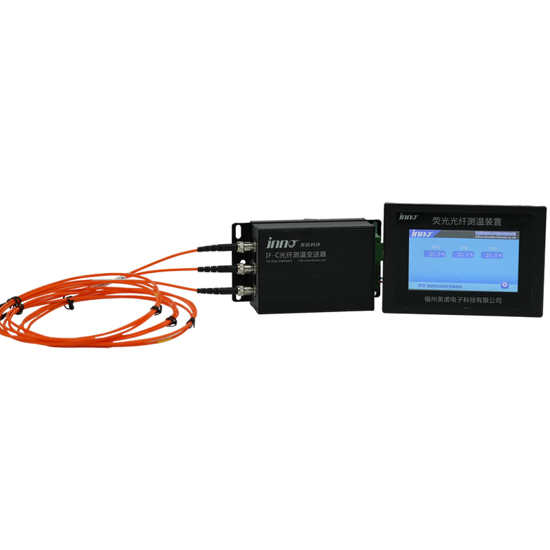
Arc Detection + Fibre Optic Temperature Monitoring

Elevated contact resistance caused by loose connections, oxidised busbars, or overloaded cables produces localised heating — a thermal precursor to arc faults. Fibre optic temperature monitoring systems, which use fluorescent fibre optic sensors to measure temperature at busbar connections, cable lugs, and circuit breaker contacts, detect these thermal anomalies in real time. When a hotspot is identified by the temperature monitoring system, maintenance teams can act before the thermal runaway leads to an arc flash event. The arc detection system then provides backup protection if the temperature-related fault progresses faster than anticipated.
| Technology | Primary Function | Detection Timescale | Role in Protection Strategy |
|---|---|---|---|
| Arc Detection | Arc flash event response | 1–10 ms (real-time response) | Last line of defence — limits arc energy |
| Partial Discharge Monitoring | Insulation degradation trending | Weeks to months (predictive) | Early warning — enables planned maintenance |
| Fibre Optic Temperature Monitoring | Hotspot and thermal anomaly detection | Minutes to hours (condition-based) | Thermal precursor warning before arc fault |
| Overcurrent Protection | Fault current interruption | 60 ms – 500 ms (backup) | Backup protection outside arc detection zone |
9. Arc Detection System Communication and Trip Integration: IEC 61850 and Modbus
IEC 61850 GOOSE Messaging for Instantaneous Trip
For installations where multiple switchgear panels are networked, IEC 61850 GOOSE (Generic Object Oriented Substation Event) messaging provides the fastest available communication mechanism for inter-device tripping. An arc detection relay equipped with IEC 61850 can transmit a GOOSE trip message to the upstream incomer breaker relay in under 4 ms from arc detection — without relying on hardwired pilot cables. This is particularly valuable in busbar protection schemes where a busbar arc flash must result in simultaneous tripping of all feeder breakers.
Hardwired Trip Output — Speed and Reliability
Where IEC 61850 networking is not available, the arc detection relay uses hardwired trip output contacts — typically volt-free relay contacts or solid-state outputs — connected directly to the trip coil circuit of the relevant circuit breakers. This is the fastest and most reliable trip mechanism. Signal transmission is limited only by cable propagation delay, which is negligible over the typical distances inside a switchboard.
Modbus RTU / TCP for SCADA Integration
Arc detection relays typically support Modbus RTU or Modbus TCP communication for integration with plant SCADA systems and asset management platforms. Through Modbus, the following data can be retrieved: arc detection event logs (timestamp, zone, duration), relay self-diagnostic status, sensor health indicators, and current-check values recorded at the time of each arc event. This data is invaluable for post-event analysis, insurance reporting, and maintenance planning.
Integration with Busbar Protection and Auto-Reclosing Schemes
In utility substation applications, the arc detection relay output must be co-ordinated with the busbar protection relay to ensure correct zone-selective tripping. In feeders where auto-reclosing is applied, the arc detection trip signal must inhibit the auto-reclose function — an arc flash inside a switchgear panel is not a transient fault and must never be followed by an automatic reclose attempt. These interlocking requirements should be defined at the design stage and verified during commissioning.
10. How to Select the Right Arc Detection System for Your Project?
Step 1 — Define the System Voltage and Switchgear Type
Confirm the system voltage (6.6 kV, 10 kV, 11 kV, 22 kV, 33 kV, or 35 kV) and the switchgear type (metal-clad, metal-enclosed, or open-type). The arc detection sensor must be rated for installation in the electromagnetic environment inside the switchgear at the relevant voltage level. Verify compliance with IEC 62271-200 for metal-enclosed switchgear.
Step 2 — Count Compartments and Define Protection Zones
Map every switchgear compartment that requires arc detection coverage: busbar chambers, circuit breaker chambers, and cable termination chambers. Each compartment constitutes one protection zone. Calculate the total number of sensors and relay input channels required. For large switchboards, assess whether a centralised relay or distributed relay architecture is more appropriate.
Step 3 — Choose Sensor Type Based on Compartment Geometry
Select loop-type fibre optic sensors for large, open busbar chambers where wide-area coverage is required. Use point-type fibre optic sensors for small, well-defined compartments such as individual circuit breaker cells. Consider photoelectric sensors for applications where fibre routing is impractical or where panel OEM integration is required.
Step 4 — Verify Communication Protocol Compatibility
Confirm the communication protocol supported by your substation automation system or SCADA platform — IEC 61850, Modbus RTU, Modbus TCP, DNP3, or Profibus. Select an arc detection relay that natively supports the required protocol without additional protocol converters.
Step 5 — Confirm Certification and Standards Compliance
For projects subject to utility grid connection requirements or international procurement standards, verify that the arc detection system holds relevant third-party type test certificates. Key standards include IEC 62271-200, IEEE 1584 for arc flash energy calculation validation, and the arc detection performance standards specified in ANSI/IEEE C37.20.7 (guide for testing switchgear rated for internal arcing faults).
11. Common Installation Mistakes and How to Avoid Them
Mistake 1: Installing sensors outside the arc flash hazard zone
Arc detection sensors must be positioned inside the switchgear compartment, facing the area most likely to produce an arc flash. Sensors mounted on the external panel surface or inside secondary instrument compartments do not have a direct optical path to potential arc source locations and may fail to detect a fault in time. Always verify the sensor’s field of view covers the primary conductor connections, contacts, and insulating components within the compartment.
Mistake 2: Disabling the current-check function to increase sensitivity
Some engineers disable the current-check confirmation logic in an attempt to maximise detection sensitivity. This creates a serious risk of false tripping on non-fault light sources such as maintenance torches, inspection cameras, or light entering through damaged panel seals. Always retain the dual-criterion (light plus current) logic. If false tripping remains a concern, review the optical threshold setting rather than disabling the current check.
Mistake 3: Exceeding the maximum fibre length specification
Running fibre optic sensor cables beyond the manufacturer’s maximum rated length introduces optical attenuation that reduces detection sensitivity. If the layout of the switchboard requires long fibre runs, use the manufacturer’s recommended low-loss fibre type and verify end-to-end attenuation with an optical power meter during commissioning.
Mistake 4: Failure to co-ordinate with the auto-reclose scheme
On feeders where automatic reclosing is enabled, an arc detection trip must inhibit the reclose function. Failing to implement this interlock will result in the circuit breaker closing back onto a live arc flash — a potentially catastrophic outcome. Always include arc detection trip as a reclose inhibit input in the protection scheme design and verify it during factory acceptance testing (FAT).
Mistake 5: No functional commissioning test after installation
An arc detection system that is installed but never functionally tested cannot be relied upon in service. Always perform a commissioning test using a controlled light source (such as a photographic strobe calibrated to simulate arc flash luminosity) introduced into each sensor zone. Verify that the relay correctly detects the light signal, confirms the current check (using a simulated secondary injection), and issues the trip output within the specified response time.
12. Frequently Asked Questions (FAQ)
Q1: What does arc detect mean in electrical protection?
Arc detect refers to the process of identifying an arc flash event inside electrical switchgear or distribution equipment using optical sensors that respond to the intense light produced when an arc forms. An arc detection system uses this optical signal — confirmed by a simultaneous rise in fault current — to issue an ultra-fast trip command to the relevant circuit breakers, limiting the arc flash energy released.
Q2: How fast is arc detection compared with overcurrent protection?
A properly designed arc detection system achieves total fault clearance — from arc inception to circuit breaker trip — in 1 to 10 ms. A conventional overcurrent relay typically requires a minimum of 60 ms and may take 100–500 ms depending on relay grading requirements. This speed advantage results in an arc flash energy reduction of 80–95%, significantly reducing the risk of severe burns and equipment damage.
Q3: Can arc detection be retrofitted to existing switchgear?
Yes. Most arc detection sensors — particularly point-type and loop-type fibre optic sensors — can be installed inside existing switchgear compartments without major modifications to the panel structure. The arc detection relay is mounted in the secondary instrumentation cubicle and connected to the existing protection CT circuits for current-check confirmation. Retrofit installation is typically carried out during a scheduled maintenance outage.
Q4: Will an arc detection system cause false trips?
A correctly configured arc detection system with dual-criterion logic (light plus current) has an extremely low false trip rate. The simultaneous requirement for both an optical flash above threshold and a fault current above the current-check setting effectively eliminates false tripping from ambient light sources, inspection torches, or gradual insulation heating. Proper threshold setting during commissioning is essential to maintain this selectivity.
Q5: How many switchgear compartments can one arc detection relay protect?
Depending on the relay model, a single arc detection relay can protect 4 to 24 compartments simultaneously, with each sensor input assigned to an independent protection zone. Larger switchboards with many panels may use multiple relays networked via IEC 61850 for co-ordinated busbar protection.
Q6: Does an arc detection system require periodic calibration?
Arc detection systems do not require calibration in the same sense as measurement instruments. However, a functional verification test using a calibrated light source should be performed annually, or after any maintenance work that could affect sensor positioning or fibre integrity. The relay’s self-diagnostic functions (which continuously monitor sensor connectivity and relay hardware health) should be checked at each periodic maintenance visit.
Q7: What is the difference between arc detection and partial discharge monitoring?
Partial discharge (PD) monitoring is a predictive technology that detects early-stage insulation degradation — typically months or years before an arc flash occurs — by measuring the tiny current pulses generated by localised dielectric breakdown. Arc detection is a reactive protection technology that responds to an arc flash event after it has already started, limiting the energy released. They serve entirely different purposes and are most effective when deployed together as complementary layers of a switchgear health management programme.
Q8: Which communication protocol does an arc detection relay support?
Modern arc detection relays support a range of communication protocols including IEC 61850 (for GOOSE-based substation automation), Modbus RTU and Modbus TCP (for SCADA integration), and in some designs DNP3 or Profibus. The choice of protocol depends on the existing substation automation architecture. IEC 61850 GOOSE is strongly recommended where inter-device tripping speed is critical.
Q9: What standards apply to arc detection systems?
The primary standards governing arc detection and arc flash protection include IEC 62271-200 (AC metal-enclosed switchgear and controlgear for rated voltages above 1 kV), IEEE 1584 (guide for performing arc flash hazard calculations), ANSI/IEEE C37.20.7 (guide for testing metal-enclosed switchgear rated for internal arcing faults), and NFPA 70E (standard for electrical safety in the workplace). National grid codes and utility technical specifications may impose additional requirements.
Q10: Is arc detection suitable for 6 kV, 10 kV, and 35 kV switchgear?
Yes. Arc detection technology is applicable across the full medium voltage range from 6.6 kV to 36 kV and beyond. The sensor type, optical sensitivity settings, and current-check threshold must be selected and configured to match the specific voltage level, fault current magnitude, and switchgear compartment geometry of the installation. Arc detection is also increasingly being applied in low-voltage main distribution boards (LV MDBs) where high-current bus fault energy levels justify the investment.
Disclaimer: The information provided in this article is for general educational and reference purposes only. It does not constitute professional engineering advice. While every effort has been made to ensure accuracy, www.fjinno.net assumes no liability for any errors, omissions, or consequences arising from the use of this information. Always consult qualified electrical engineers and follow applicable local codes, standards, and safety regulations when specifying, installing, or operating arc detection systems and arc flash protection equipment. Product specifications and performance data mentioned herein are representative and may vary by manufacturer.
Customer Reviews
Rated
4.8
out of
5
— based on
47 verified customer reviews.
★★★★★
James T.
We retrofitted arc detection sensors into 24 existing 11 kV panels without any shutdown. The fibre optic sensors clamp on cleanly and the relay integration with our IEC 61850 protection scheme was straightforward. Response time verified at under 5 ms during commissioning. Highly recommended for any utility-grade arc flash mitigation project.
★★★★★
Ahmed R.
Excellent product quality and competitive pricing for OEM procurement. The dual-criterion logic has eliminated false trips entirely across our 10 kV substation. Our maintenance team now has full confidence that arc flash incident energy is controlled at every panel. Technical documentation is thorough and covers all configuration scenarios.
★★★★★
David M.
We combined the arc detection system with fibre optic temperature monitoring on the same switchboard. The multi-layer protection approach gives us both predictive insulation condition awareness and reactive arc flash protection. INNO’s technical support team was very responsive during the system design and commissioning phases.
★★★★☆
Nguyen H.
Good performance at 22 kV level. The loop-type fibre sensors cover the full busbar chamber without any blind spots. Communication via Modbus TCP to our SCADA system works reliably. Would appreciate more detailed commissioning documentation provided in additional languages alongside English.
★★★★★
Carlos S.
Fast shipping and solid build quality. The arc detection relay passed our factory acceptance testing on the first attempt. All sensor channels functional, GOOSE trip verified with test set within specification. The pre-sales team helped us correctly size the system for a 16-panel board. Very satisfied with the overall procurement and technical experience.
★★★★★
Mark L.
Deployed on a 6.6 kV MCC in a petrochemical plant where arc flash hazard reduction was a regulatory requirement. The point-type sensors fit perfectly inside the existing motor feeder compartments. Incident energy calculations confirmed a reduction from Category 4 to Category 2 PPE requirement after arc detection installation. Excellent outcome for our safety programme.

Fiber optic temperature sensor, Intelligent monitoring system, Distributed fiber optic manufacturer in China
 |
 |
 |