 INNO fibre optic temperature sensors ,temperature monitoring systems.
- A fiber optic thermometer uses light — not electricity — to measure temperature, making it intrinsically immune to electromagnetic interference (EMI) and safe for direct contact with live high-voltage conductors.
- The dominant sensing technology is fluorescence decay: a phosphor crystal at the fiber tip emits light whose fade time is a precise, absolute function of temperature — no drift, no recalibration required over a 25-year service life.
- Fiber optic temperature sensors outperform thermocouples, RTDs, and wireless sensors in high-voltage switchgear, power transformer windings, MRI scanners, semiconductor equipment, and battery packs — environments where metallic sensors either fail or pose safety hazards.
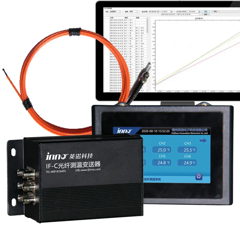
- A complete fiber optic temperature measurement system pairs the sensing probe with a multi-channel transmitter, configurable alarm outputs, and standard communication interfaces (RS485 Modbus RTU, IEC 61850, 4–20 mA) for SCADA or DCS integration.
- Measurement accuracy reaches ±0.5–1°C across a range of −40°C to +260°C, with probe insulation ratings up to 140 kV — specifications unattainable by any competing contact temperature technology.
1. What is a Fiber Optic Thermometer?

- Definition. A fiber optic thermometer is a temperature measurement instrument that uses an optical fiber as the signal transmission medium and a photosensitive element — typically a phosphor crystal or fiber Bragg grating — as the sensing element. Unlike conventional thermometers that carry an electrical signal through a metal conductor, a fiber optic thermometer transmits only light, which means the sensor is entirely non-conductive and generates no electromagnetic emission at the measurement point.
- The fundamental advantage over electronic sensors. Every thermocouple, RTD, and wireless sensor on the market relies on metal conductors or electronic circuits at or near the sensing point. In strong electromagnetic fields — inside energized switchgear, power transformer windings, induction heaters, or MRI scanners — those conductors pick up interference that corrupts the reading or creates safety hazards. A fiber optic temperature sensor has no metal at the probe tip; light cannot be inductively coupled, so the measurement is immune to EMI regardless of the surrounding field strength.
- Scope of the technology. The term “fiber optic thermometer” encompasses the complete measurement chain: the fiber optic sensing probe, the optical fiber cable (which may extend 0–20 m or more), the signal demodulation transmitter (which converts optical decay data into a calibrated temperature value), and the communication output to a display, controller, or SCADA system. In industrial practice, the probe and transmitter together form a fiber optic temperature monitoring unit that may serve 1 to 32 measurement points simultaneously.
- Who uses fiber optic thermometers. Utilities and grid operators use them for transformer winding hot-spot monitoring and switchgear busbar surveillance. Industrial manufacturers deploy them in motors, reactors, semiconductor furnaces, and microwave processing equipment. Medical device engineers integrate them into MRI scanners, HIFU systems, and RF ablation catheters. Battery and electric vehicle developers embed them in cell assemblies for thermal management. The common thread across all these applications is the need for accurate, continuous temperature data in an environment where conventional metallic sensing fails.
2. How Does a Fiber Optic Thermometer Work?

The Fluorescence Decay Principle
- Step 1 — LED excitation. A pulsed blue or UV LED, housed in the transmitter electronics unit, sends a brief light pulse down the optical fiber toward the probe tip. The fiber carries only light — no electrical signal — so the full length of cable between transmitter and probe is completely non-conductive and EMI-transparent.
- Step 2 — Fluorescence emission. At the probe tip, the LED pulse strikes a rare-earth phosphor crystal that is permanently bonded to the fiber end. The crystal absorbs the light and immediately re-emits it at a longer wavelength — it fluoresces. This fluorescence is not an instantaneous flash; it decays over a characteristic time that is a precise, physics-based function of the crystal’s temperature at that exact moment.
- Step 3 — Decay time measurement. The emitted fluorescence travels back along the same fiber to a photodetector in the transmitter. The transmitter measures the fluorescence lifetime — how quickly the intensity decays from peak to baseline. Because this decay time is governed by fundamental quantum mechanics of the phosphor material, it does not drift with component aging, vibration, or chemical exposure. One calibration at the factory remains valid for the entire 25-year service life.
- Step 4 — Temperature output. The transmitter applies a stored calibration curve to convert the measured decay time into a precise temperature value in °C or °F, then outputs the reading via RS485 Modbus RTU, 4–20 mA analog, or IEC 61850 protocol to any connected display, SCADA system, data logger, or protection relay. The entire acquisition cycle — excitation, decay measurement, and output — completes in under one second, enabling real-time thermal monitoring with near-instantaneous response to temperature changes.
3. Fiber Optic Thermometer vs. Thermocouple vs. RTD vs. Infrared Thermometer

The table below compares the four most widely used industrial temperature measurement technologies across the dimensions that matter most when specifying instrumentation for demanding applications.
| Criterion | Fiber Optic Thermometer | Thermocouple | RTD (Pt100 / Pt1000) | Infrared Thermometer |
|---|---|---|---|---|
| Measurement type | Contact — direct probe at measurement point | Contact — junction at measurement point | Contact — resistance element at measurement point | Non-contact — surface radiation detection |
| EMI immunity | ✓ Complete — 100% immune, all-optical signal | ✗ Poor — metal leads act as antenna | ✗ Moderate — susceptible in strong fields | ✓ Good — optical detection, no metal leads |
| High-voltage safety | ✓ Fully dielectric, 100–140 kV rated | ✗ Galvanic connection — isolation required | ✗ Galvanic connection — isolation required | ⚠ Non-contact, but limited to surface access |
| Typical accuracy | ±0.5–1°C (calibration-free for 25 years) | ±1–3°C (drifts — periodic recalibration needed) | ±0.1–1°C (but degrades with vibration / lead resistance) | ±2–5°C (surface emissivity dependent) |
| Continuous 24/7 monitoring | ✓ Yes — standard operating mode | ✓ Yes | ✓ Yes | ✗ Typically periodic inspection only |
| Maintenance and service life | Zero maintenance — 25+ year life, no recalibration | Junction oxidizes — recalibrate or replace every 2–5 years | Vibration damage, lead resistance drift — periodic service required | Lens cleaning, detector aging — periodic service required |
- Why thermocouples fall short in electrical environments. A thermocouple’s output is measured in millivolts. Inside energized switchgear or a power transformer, stray electromagnetic fields induce voltages of the same order of magnitude into the thermocouple leads, corrupting the reading entirely. Shielding adds cost and complexity without fully solving the problem. A fluorescent fiber optic temperature sensor has no voltage to corrupt — the signal is a time measurement (decay duration), not an amplitude measurement.
- Why RTDs are inadequate for high-voltage applications. A Pt100 or Pt1000 RTD requires a DC excitation current through its metallic element, creating a galvanic connection to the measurement point. In a high-voltage winding or on an energized busbar, that connection is a direct safety hazard requiring costly isolation barriers. Fiber optic probes are entirely dielectric from tip to transmitter — no isolation hardware is needed at any voltage level.
- Why infrared thermometers cannot replace fiber optics in enclosed equipment. Infrared thermometers measure the surface temperature of whatever is visible within their field of view. They cannot see inside a sealed transformer tank, behind insulation wrap on a winding conductor, or inside a switchgear cubicle with doors closed. Fiber optic probes are embedded directly at the measurement point, providing access to internal temperatures that infrared instruments can never reach.
- Total cost of ownership comparison. Fiber optic sensors carry a higher upfront purchase price than thermocouples or RTDs of equivalent accuracy. Over a 15–25 year asset lifecycle, however, the absence of recalibration labor, replacement parts, and failure-related downtime consistently delivers a lower total cost of ownership than any competing technology — particularly when the cost of a single missed thermal event is factored into the calculation.
4. Types of Fiber Optic Thermometers
- Fluorescent decay thermometers. The most widely deployed type in industrial and power applications. A phosphor crystal at the fiber tip emits fluorescence with a decay time that varies precisely with temperature. Advantages include absolute measurement (no reference junction), EMI immunity, calibration-free stability over decades, and operation across −40°C to +260°C. The fluorescent fiber optic temperature sensor family is the commercial mainstream for transformer, switchgear, motor, and medical applications. All fiber optic temperature sensors manufactured by FJINNO use this principle.
- Fiber Bragg Grating (FBG) sensors. A periodic refractive index pattern inscribed into the fiber core reflects a specific wavelength of light that shifts with temperature and strain. FBG sensors can be multiplexed along a single fiber at multiple points and are valued in structural health monitoring and aerospace applications. They require a broadband light source and spectrometer-grade interrogator, making the system more complex and expensive than fluorescent types for pure temperature measurement.
- Distributed Temperature Sensing (DTS). Uses Raman backscattering along an ordinary single-mode or multi-mode fiber to generate a continuous temperature profile over distances of up to 30–50 km, with spatial resolution of approximately 1 meter. Ideal for long power cable routes, pipeline monitoring, and tunnel fire detection where the fault location is unknown in advance. DTS systems are substantially more complex and expensive than point-based sensors and are typically used in infrastructure rather than equipment monitoring.
- Blackbody radiation thermometers (fiber optic pyrometers). A sapphire or quartz fiber guides thermal radiation emitted by a target surface to an external photodetector. Used for very high temperature applications — typically above 500°C up to 3000°C — in metal processing, semiconductor crystal growth, and furnace control. This type is non-contact (at the hot end) and does not require physical contact with the material being measured, but is limited to high-temperature applications where radiation is measurable.
5. Fluorescent Fiber Optic Temperature Sensor — Core Technology
- Probe construction and materials. The sensing element is a rare-earth phosphor crystal — typically based on ruby (chromium-doped aluminum oxide) or a proprietary oxide compound — permanently bonded to the polished end of a glass optical fiber. The entire probe tip assembly is non-metallic and non-conductive. Standard probe diameters range from 2 to 3 mm, making them small enough for installation on transformer winding conductors or switchgear contact fingers without structural modification. The fluorescent fiber optic temperature sensor probe is available in multiple tip geometries to suit flat surfaces, cylindrical conductors, and confined-space installations.
- Why the measurement does not drift. The fluorescence decay time of a phosphor crystal is determined by the crystal’s lattice structure and the quantum energy levels of its dopant ions — properties that do not change with age, oxidation, mechanical stress, or exposure to oil, chemicals, or radiation. A thermocouple junction changes its Seebeck coefficient as the junction metal oxidizes or diffuses over time; an RTD’s resistance changes as its platinum wire fatigues under vibration. Neither aging mechanism applies to a phosphor crystal, which is why one factory calibration remains valid for the sensor’s entire 25-year operating life.
- High-voltage insulation performance. The glass fiber and non-metallic probe housing provide electrical isolation that exceeds 100–140 kV AC withstand voltage in standard FJINNO designs. This makes the fluorescent fiber optic temperature probe unique among contact sensors: it can be physically bonded to energized conductors at medium and high voltage levels without requiring additional isolation barriers, current transformers, or safety interlocks. This capability is critical for embedding sensors in transformer windings during manufacture or retrofitting them in live switchgear during a brief maintenance window.
- Probe customization options. Probe diameter, fiber length (standard 0–20 m, extended on request), jacket material (standard PTFE, polyimide for chemical resistance, stainless steel armor for mechanical protection, silicone for high-flexibility installations), connector type, and tip geometry are all configurable to the application. OEM customers can request custom form factors, branded packaging, and specific calibration ranges. The polyimide-enhanced fluorescent fiber optic temperature sensor offers outstanding resistance to aggressive chemicals and high-temperature environments where standard PTFE jacketing would be insufficient.
6. Key Specifications of a Fiber Optic Temperature Probe
Standard Performance Parameters
- Temperature range and accuracy. Standard fiber optic temperature probes cover −40°C to +260°C with ±1°C accuracy and 0.1°C resolution. A high-accuracy variant achieves ±0.5°C across the same range. Extended-range probes for high-temperature industrial applications — furnaces, induction heaters, semiconductor equipment — operate up to 300°C or beyond in specialized configurations. The high-precision high-temperature and low-temperature resistant fluorescent fiber optic temperature sensor covers extreme ranges with maintained precision across the full span.
- Response time and channel capacity. Response time is under one second for standard configurations — sufficient for all thermal protection and monitoring applications in electrical equipment. The transmitter electronics accommodate 1, 3, 4, 6, 9, 16, or up to 32 independent sensor channels in a single chassis, enabling comprehensive multi-point monitoring of a transformer, switchgear panel, or motor from a single instrument without the installation complexity of multiple independent units.
- Electrical and insulation ratings. Probe insulation voltage: 100–140 kV AC withstand (standard); higher ratings available on request. The transmitter electronics operate on AC/DC 220 V or 24 V DC supply and carry standard CE and RoHS markings. Communication outputs: RS485 Modbus RTU (standard), 4–20 mA analog output (optional), IEC 61850 GOOSE and MMS (optional for digital substations). Relay alarm outputs: typically 2–4 dry contact relays per transmitter, configurable for pre-alarm, alarm, and trip thresholds.
- Mechanical and environmental ratings. Standard probe outer diameter: 2.5 mm. Fiber length: 0–20 m (customizable). Operating environment: −40°C to +85°C ambient for the transmitter, with the probe rated to the measurement range. IP54 or IP65 transmitter enclosures are standard; IP67 and custom enclosures are available for outdoor or harsh-environment installations. Probe jacket materials are selected to match the installation environment — oil-immersed, gas-filled, chemical, or mechanical-exposure service. Extension cables for fluorescent fiber optic temperature sensors allow probe-to-transmitter distances beyond the standard factory fiber length without signal degradation.
7. Fiber Optic Thermometer vs. Related Terms — What Is the Difference?
The following terms appear frequently in product catalogs, technical standards, and supplier websites, often used interchangeably. The table clarifies what each term precisely refers to, helping engineers and procurement teams specify correctly.
| Term | What It Refers To | Physical Form | Includes Electronics / Transmitter? | Typical Context |
|---|---|---|---|---|
| Fiber Optic Thermometer | Complete temperature measurement instrument using optical fiber as the signal medium | Probe + fiber cable + transmitter unit + display or output | Yes — full measurement system | Product name / instrument category; used in catalogs and standards |
| Fiber Optic Temperature Sensor | The sensing element — probe and fiber — that detects temperature optically | Probe tip + fiber cable (sensor only, no transmitter) | No — sensor only; requires a separate transmitter | Procurement term; what engineers order as a replaceable field component |
| Fiber Optic Temperature Probe | The physical probe element at the measurement point — the phosphor tip and its immediate housing | Probe tip assembly only (may include short fiber pigtail) | No — probe component only | Component-level term used in OEM integration and repair |
| Fiber Optic Temperature Measurement System | The complete installed system including sensors, transmitters, wiring, software, communication, and SCADA integration | Full system — hardware + software + communication infrastructure | Yes — includes all hardware and software components | Project and tender term; used when procuring a complete monitoring solution |
- In everyday engineering usage. “Fiber optic thermometer” and “fiber optic temperature sensor” are often used interchangeably to mean the complete sensing unit — probe plus transmitter — sold as a packaged product. The distinction matters primarily in OEM contexts where a customer purchases only the probe assembly for integration into their own instrument, or at the system-design level where the full measurement system architecture must be specified.
- In procurement and tendering. Tender specifications for power infrastructure projects typically call for a “fiber optic temperature measurement system” and list performance requirements (channel count, accuracy, communication protocol, alarm outputs) separately from the sensing probe specifications. Understanding that “system” implies the full chain — probe, transmitter, software, and integration — prevents scope gaps between the supplier’s quotation and the engineer’s design intent.
- Manufacturer vs. standards usage. IEC standards (IEC 60076, IEC 62271) use “temperature sensor” or “winding temperature indicator” as the generic term, without specifying the sensing technology. IEEE standards (C57.91) refer to “optical fiber temperature sensors” specifically when describing direct hot-spot measurement inside transformer windings. Both bodies recognize the fiber optic approach as the reference method for the most accurate internal temperature measurement.
- Practical implication for this article. Throughout the remainder of this guide, “fiber optic thermometer,” “fiber optic temperature sensor,” and “fiber optic temperature probe” are used in their technically precise senses as defined above. When the full monitoring solution — including transmitter, alarms, and communication — is being discussed, the term “fiber optic temperature monitoring system” is used explicitly.
8. Fiber Optic Temperature Measurement for Power Transformers
- Why direct winding measurement is necessary. Conventional transformer protection relies on a Winding Temperature Indicator (WTI) — an instrument that estimates winding temperature by adding a calculated temperature rise to the top-oil measurement. This thermal model can underestimate the actual winding hot spot by 10–15°C under transient loading conditions. That gap directly translates to accelerated insulation aging that goes undetected until a failure occurs. A fiber optic temperature sensor embedded in the winding measures the actual hot-spot temperature with ±1°C accuracy, eliminating the estimation error entirely.
- Oil-immersed transformer winding probes. For oil-immersed power transformers, the sensing probe must survive decades of continuous immersion in transformer mineral oil at temperatures up to 200°C, while maintaining 100+ kV electrical isolation and resisting mechanical stress from winding movement during fault conditions. The armored fluorescent fiber optic temperature sensor for oil-immersed transformer windings addresses all of these requirements: its stainless-steel armored jacket provides mechanical protection during transformer winding and installation, while the all-glass, non-metallic sensing element ensures permanent electrical isolation and oil compatibility throughout the transformer’s operating life.
- Dry-type transformer winding measurement. Cast-resin and vacuum-pressure-impregnated (VPI) dry-type transformers are increasingly common in data centers, commercial buildings, and industrial switchrooms. Their windings operate at air or resin interface temperatures that directly affect resin insulation life. The fluorescent fiber optic temperature sensor winding tube for transformer winding temperature measurement is designed for embedding in cast-resin windings during manufacturing, with a form factor and mechanical specification matched to the winding process used by leading dry-type transformer manufacturers worldwide.
- System configuration and protection integration. A typical power transformer installation uses 6–16 fiber optic sensing probes distributed across the high-voltage and low-voltage windings, the core, and the oil at the top and bottom of the tank. The multi-channel transmitter monitors all points simultaneously and provides alarm relay outputs connected to the transformer protection panel — activating cooling fan stages as temperature rises, triggering an overtemperature alarm when the hot spot approaches the rated limit, and issuing a trip command if the limit is exceeded. Integration with IEEE C57.91 loading calculations enables real-time insulation aging assessment and dynamic load management.
9. Fiber Optic Temperature Sensor for Switchgear Busbar and Contacts
- The thermal failure mechanism in switchgear. Bolted busbar joints and circuit breaker contact fingers are the primary thermal failure points in medium-voltage and high-voltage switchgear. Resistance at a loose or degraded joint generates heat proportional to the square of the current — a joint with 10% higher contact resistance than design generates 21% more heat under the same load. That heat accumulates silently inside the closed cubicle, invisible to any external inspection method until the insulation discolors, the switchgear begins to smell, or an arc flash occurs.
- Continuous contact-point monitoring. Mounting a fiber optic temperature sensor for busbar and bolt connections directly on the conductor surface at each joint provides continuous, real-time temperature data at the exact locations where thermal faults originate. The 2.5 mm probe diameter allows installation on virtually any busbar geometry without requiring structural modification of the switchgear panel. The probe’s 140 kV insulation rating makes it safe for installation on medium-voltage conductors at 6 kV, 10 kV, 20 kV, and 35 kV without any additional isolation hardware.
- Phase differential alarm logic. A three-phase switchgear panel has three identical busbars carrying the same load current simultaneously. Under healthy conditions, all three phases run within a few degrees of each other. When one phase’s joint begins to degrade, its temperature rises while the other two remain stable — creating a phase temperature differential that is highly specific to contact degradation and is detectable well before the absolute temperature reaches an alarm threshold. This differential logic eliminates the nuisance alarms that absolute thresholds alone generate during legitimate heavy-load periods.
- Coverage points and retrofit installation. Best practice for a standard three-phase MV cubicle is 6–9 sensors: three on incoming busbar joints, three on outgoing cable termination lugs, and optionally three on circuit breaker contact fingers. All probes can be installed during a single scheduled maintenance outage of typically 2–4 hours, with no panel redesign and no permanent modification to the switchgear structure. The fiber leads exit the cubicle through existing cable entry points and connect to the transmitter mounted in an adjacent low-voltage compartment.
10. Fiber Optic Thermometer for Motor and Generator Winding Monitoring
- Motor winding failure and thermal root cause. According to industry surveys, between 30% and 40% of electric motor failures in heavy industry are attributable to insulation failure caused by overheating. Motor thermal overload relays use current sensing to estimate winding temperature — but they cannot account for blocked ventilation, increased ambient temperature, unbalanced phase loading, or cooling system degradation. A motor winding temperature sensor based on fiber optic technology measures actual stator slot temperatures directly, giving protection systems accurate data to act on rather than calculated estimates that may be wrong by 20–40°C in adverse conditions.
- EMI environment inside a motor stator. The stator winding of a large electric motor or generator operates in one of the most electromagnetically hostile environments imaginable — surrounded by rotating magnetic flux at 50 or 60 Hz and harmonics generated by variable-frequency drives. Embedding a metallic temperature sensor in this environment requires careful shielding to achieve even moderate accuracy. A fluorescent fiber optic probe embedded in the winding slot experiences the same magnetic flux but responds only to temperature, producing an accurate reading regardless of the surrounding field intensity.
- Generator and hydro turbine stator monitoring. Large hydro and thermal power plant generators run continuously at high load factors for years between scheduled overhauls. A developing hot spot in the stator insulation, if undetected, can cause a winding-to-ground fault that forces an emergency shutdown and requires months of repair work — a catastrophic outcome in a baseload generation asset. Fiber optic sensors embedded in the stator winding during manufacture or at overhaul provide the continuous, drift-free thermal data needed to catch insulation degradation early and schedule the next maintenance outage at a convenient time.
- Wind turbine nacelle and transformer monitoring. Wind turbine generators and their integrated step-up transformers present access challenges — the nacelle is hundreds of meters in the air, and maintenance visits are expensive and weather-dependent. Fiber optic fiber optic temperature monitoring systems installed during turbine commissioning provide continuous generator winding and transformer winding temperature data via the turbine SCADA system, enabling condition-based maintenance decisions to be made from the control room without a technician climbing the tower for an inspection.
11. Fiber Optic Temperature Measurement in Medical Applications
- Why metallic sensors are incompatible with medical imaging and ablation. MRI scanners operate inside a powerful static magnetic field (1.5 T to 7 T in clinical use) combined with rapidly switched gradient fields and RF pulse sequences. Any metallic object inside the bore experiences force, torque, and induced heating — making conventional metallic temperature sensors not only inaccurate but actively dangerous to the patient and the equipment. The same constraints apply to high-frequency RF ablation, HIFU (High-Intensity Focused Ultrasound), and laser interstitial thermal therapy — all of which generate strong electromagnetic or acoustic fields that corrupt metallic sensor readings.
- Medical-grade fiber optic temperature sensors. The MRI RF NMR laser ablation HIFU fiber optic temperature sensor is designed specifically for these environments. Its sensing element and probe housing contain zero metallic components — no metal wires, no metallic housings, no conductive coatings. The probe is MRI-compatible, transparent to RF fields, and produces accurate temperature readings regardless of gradient switching sequences or RF pulse power. Probe geometries as small as 0.5–1 mm diameter are available for catheter-integrated and needle-insertable configurations used in interventional radiology and thermal therapy.
- NMR and spectroscopy applications. NMR spectrometers require precise temperature control of the sample and magnet system, typically to within 0.1°C. Conventional temperature sensors cannot operate inside the magnet bore without perturbing the measurement field. Fiber optic temperature probes, being entirely non-magnetic and non-conductive, can be positioned directly in the sample zone to provide accurate temperature feedback to the temperature control system without affecting spectral quality.
- Regulatory and safety context. Medical device applications require components to meet stringent biocompatibility, sterility, and electrical safety standards. Fiber optic probes used in direct patient-contact or implantable applications are manufactured from medical-grade materials and validated for biocompatibility per ISO 10993. Non-patient-contact applications in medical equipment (magnet thermal management, RF amplifier cooling monitoring) use standard industrial fiber optic probes within the relevant IEC 60601 equipment safety framework.
12. Fiber Optic Thermometer for Semiconductor and Industrial Heating Processes
- Semiconductor fabrication equipment. Processes such as chemical vapor deposition (CVD), rapid thermal processing (RTP), plasma etching, and wafer annealing require precise temperature control at the wafer surface or susceptor — often in vacuum chambers under intense RF or microwave energy. Metallic sensors introduce contamination risk, disturb the process field, and may create particle sources from thermal cycling stress. A fiber optic thermometer with a sapphire or high-purity quartz probe can operate in ultra-high vacuum, withstand aggressive process chemistries, and provide accurate temperature feedback without perturbing the plasma or RF field.
- Microwave and RF heating applications. Industrial microwave drying systems, RF curing ovens, and dielectric heating equipment generate intense microwave fields (typically 915 MHz or 2.45 GHz) that induce heating in any conductive object placed inside the cavity. A metallic sensor inside a microwave cavity heats itself independently of the target material, producing readings that reflect sensor self-heating rather than process temperature. The high-precision high-temperature and low-temperature resistant fluorescent fiber optic temperature sensor provides accurate, unperturbed temperature measurement directly in the microwave field — a capability unique to the fiber optic approach.
- Induction heating and plasma environments. Induction heating of metal billets, continuous casting temperature monitoring, and plasma spray processes involve strong alternating magnetic fields that make thermocouple or RTD measurement impractical without elaborate field-cancellation schemes. Fiber optic probes — fully non-conductive and non-magnetic — measure temperature at the point of interest without any interaction with the induction field, enabling closed-loop temperature control of the heating process with direct feedback from the workpiece.
- Dry-type reactor and power electronics thermal management. Dry-type reactors, IGBT modules in variable-frequency drives, and SiC power devices in high-frequency converters have narrow thermal operating windows — exceeding rated junction or winding temperature by even 20–30°C accelerates insulation aging exponentially. Fiber optic temperature monitoring embedded at the hottest points of these components provides the only accurate, interference-free thermal data available for protection relay integration and condition-based maintenance scheduling in high-power electronics applications.
13. Fiber Optic Thermal Sensor for Battery Packs and Energy Storage
- Thermal runaway risk in lithium-ion batteries. Thermal runaway — a self-sustaining exothermic reaction triggered by overheating, mechanical damage, or internal short circuit — is the primary safety hazard in lithium-ion battery packs used in electric vehicles, grid-scale energy storage systems, and uninterruptible power supplies. Early detection of anomalous temperature rise at the cell or module level, before runaway propagates, is the critical function of a battery thermal monitoring system. Sub-second response time and accurate point measurement are both required.
- Eliminating the short-circuit risk of metallic sensors. The electrodes, current collectors, and busbars inside a battery pack are at different potentials. Inserting a metallic temperature sensor between cells creates a potential short-circuit path that can itself trigger the thermal event the monitoring system is designed to detect. A fluorescent fiber optic temperature sensor probe — entirely non-metallic, non-conductive, and chemically inert — can be routed between cells, through busbars, and across module boundaries without any risk of shorting or electrochemical interaction with the battery chemistry.
- Multi-point cell and module monitoring. A single fiber optic temperature transmitter with multiple channels can monitor temperatures at multiple cells, bus connections, and thermal management system interfaces simultaneously, providing the battery management system (BMS) with the spatial temperature distribution needed to identify the location of a developing thermal anomaly as well as its magnitude. This spatial awareness is not possible with simple point thermistors at the module perimeter.
- Grid-scale energy storage applications. Utility-scale battery energy storage systems (BESS) house hundreds or thousands of battery modules in large enclosures. The cost and logistics of maintaining wireless sensor batteries inside these enclosures over a 20-year system life are prohibitive. Fiber optic sensors, being passive at the measurement point (they require no power at the probe), provide continuous thermal surveillance of the entire battery bank for the system’s operating life with zero sensor-level maintenance — making them the practical choice for long-life infrastructure energy storage installations.
14. Alarm and Protection Functions in Fiber Optic Temperature Monitoring Systems
- Multi-level alarm architecture. A well-configured fiber optic temperature monitoring system implements at minimum three alarm tiers for each monitored point. The first tier — a pre-alarm or warning — is set 15–25°C below the absolute operating limit and alerts maintenance personnel to investigate. The second tier — a high-temperature alarm — is set at the maximum permissible continuous operating temperature and triggers automatic cooling activation (fan start, pump start) and operator notification. The third tier — a high-high alarm or trip — is set at the absolute thermal limit and issues a hardwired relay contact to the protection system, disconnecting the equipment to prevent irreversible damage.
- Cooling system interlock and load management. Fiber optic transmitters provide relay contact outputs that directly control cooling equipment — typically HVAC fans or oil pumps on transformers and reactors. As winding or busbar temperature rises through successive setpoints, cooling stages activate in sequence. This staged response prevents both unnecessarily noisy or energy-intensive operation of cooling fans at low loads and inadequate cooling response at peak loads. Where the load can be controlled (motor speed, transformer tap position, generator output), thermal data from the fiber optic system can be fed to the load management system to reduce current and allow temperature to stabilize below the alarm level.
- Rate-of-rise detection. A rapid temperature increase — 5°C/minute or more, for example — is a strong indicator of an active fault condition (arc, insulation breakdown, contact failure) rather than a gradual overload. Rate-of-rise detection in the transmitter’s alarm logic identifies this pattern and can escalate directly to a trip command without waiting for the temperature to reach the absolute limit, providing faster protection against rapidly developing faults. This logic is configured during system commissioning and tuned to the load profile of the specific installation.
- Alarm testing, logging, and compliance. All alarm events are time-stamped and stored in the transmitter’s internal event log (and in the SCADA historian when integrated). This record supports regulatory compliance reporting, warranty claim investigations, insurance assessments, and root cause analysis following any thermal event. Periodic alarm function tests — performed by injecting a simulated temperature signal via the transmitter’s test mode — verify that relay outputs, cooling interlock signals, and SCADA alarm notifications all remain fully functional throughout the system’s service life.
15. Installation Best Practices for Fiber Optic Temperature Sensors
- Probe placement at the measurement point. The single most important installation decision is where to place the probe. For winding hot-spot monitoring, the probe should be positioned at the conductor surface in the highest-loss winding section — typically the middle of the high-voltage winding in oil-immersed transformers, as defined by the thermal model in IEC 60076-7. For switchgear busbars, the probe is bonded directly to the conductor surface at each bolted joint using a thermally conductive adhesive or mechanical clip — the probe must maintain continuous contact with the conductor surface to track temperature changes accurately. For motor stators, probes are placed in the stator slots between winding conductors during winding manufacture or the rewind process.
- Mechanical protection of the fiber cable. The glass optical fiber core is fragile — bend radii below the minimum specified by the manufacturer (typically 20–30 mm for standard fiber) will break the fiber and render the channel non-functional. All fiber runs between the probe and transmitter should be routed through protective conduit or cable tray, with bend radii controlled by cable management hardware. In environments with mechanical vibration or abrasion risk, an armored fiber assembly or a protective flexible conduit should be used. The extension cable for fluorescent fiber optic temperature sensors is available in reinforced, abrasion-resistant constructions for demanding industrial routing environments.
- Chemical compatibility and jacket selection. Standard fiber optic probes use PTFE (Teflon) jackets that are compatible with most transformer oils, silicone fluids, and mild chemical environments. Applications involving aggressive acids, bases, or solvents require the polyimide-enhanced fluorescent fiber optic temperature sensor, whose polyimide-coated fiber construction provides substantially higher resistance to chemical attack and elevated-temperature mechanical stress compared to standard PTFE. For high-mechanical-stress environments — embedded in transformer windings subject to short-circuit forces — the stainless steel armored construction is specified.
- Commissioning and verification. After installation, each channel should be verified by observing the measured temperature against a reference measurement at the probe location — using a calibrated contact thermometer at a nearby accessible surface, or by confirming that the measured ambient temperature agrees with the known room temperature before energizing the equipment. The transmitter’s built-in self-test function should be exercised to confirm all alarm relay outputs, communication registers, and analog outputs are active and correctly scaled before the system is placed in service. Documentation of the as-installed probe positions, channel assignments, alarm setpoints, and commissioning test results should be retained in the asset’s maintenance records.
16. SCADA and PLC Integration with Fiber Optic Temperature Measurement Systems
- RS485 Modbus RTU — the universal standard output. Every FJINNO fiber optic temperature transmitter provides RS485 Modbus RTU as its primary digital communication output. Modbus RTU is the most widely supported protocol in industrial SCADA systems, DCS platforms, and programmable logic controllers — it is directly readable by Allen-Bradley, Siemens, Schneider, ABB, GE, and virtually every other major PLC and RTU on the market without any protocol conversion middleware. Temperature values, alarm status, event logs, and configuration parameters are all accessible through standard Modbus register maps provided in the product documentation.
- IEC 61850 for digital substations. Modern grid automation projects use IEC 61850 as the communication standard for all intelligent electronic devices (IEDs) in the substation. FJINNO transmitters with IEC 61850 option support both GOOSE messaging (for fast alarm and trip signal transmission) and MMS client/server (for data reporting and configuration). This allows the fiber optic temperature monitoring system to participate natively in the substation automation network alongside protection relays, bay controllers, and merging units — without requiring a separate Modbus-to-IEC-61850 gateway.
- 4–20 mA analog output for legacy systems. Many protection relays and legacy SCADA systems accept only 4–20 mA analog temperature inputs. FJINNO transmitters provide optional 4–20 mA outputs (one per channel) that can drive directly into any standard analog input card. The 4–20 mA output is loop-powered and provides galvanic isolation between the transmitter and the receiving system, eliminating ground loop issues that affect thermocouple and RTD analog circuits.
- Cloud platform and remote monitoring integration. For operators managing geographically distributed transformer or switchgear fleets — utilities with dozens of substations, industrial companies with multiple plants — cloud-based fiber optic temperature monitoring platforms provide unified visibility of all assets through a web browser or mobile app. Temperature trends, alarm histories, and maintenance recommendations are accessible from any location without requiring on-site access to the substation SCADA workstation. FJINNO provides customized cloud software development for enterprise-scale deployments requiring integration with existing asset management platforms.
17. How to Choose the Right Fiber Optic Thermometer
- Define the electromagnetic environment first. If the measurement point is inside energized electrical equipment — a transformer winding, a switchgear busbar, a motor stator, an induction heater — only a fluorescent fiber optic sensor is technically viable. If the measurement point is accessible, at low voltage, and in a non-EMI environment (e.g., a HVAC duct, a laboratory furnace with conventional power supply), RTDs or thermocouples may be adequate and more cost-effective. The choice between fiber optic and conventional sensing should be driven by the actual application requirements, not by cost alone.
- Match the probe construction to the installation environment. Oil-immersed transformer windings require an armored, oil-compatible probe. Motor stator slots require a flat or flexible probe that fits between winding conductors. Switchgear busbars require a compact, mechanically robust probe that bonds to flat or cylindrical conductor surfaces. Chemical process equipment may require a polyimide or PTFE jacket. Microwave or RF environments require a fully non-metallic probe housing with no metallic fittings anywhere along the fiber length. Selecting the wrong probe construction for the installation environment is the most common cause of premature sensor failure in field installations.
- Specify the channel count, accuracy, and communication requirements precisely. Underspecifying channel count — purchasing a 4-channel transmitter when 6 measurement points are needed — forces a second transmitter purchase and complicates integration. Overspecifying accuracy (e.g., demanding ±0.1°C when ±1°C is technically sufficient) drives unnecessary cost. Communication protocol mismatches (e.g., a transmitter with only Modbus RTU output connected to an IEC 61850-only substation automation system) require expensive gateways or system redesign. All three parameters should be confirmed with the application engineering team before placing an order.
- Evaluate the supplier’s support capability, not just the product datasheet. A fiber optic thermometer installed in a transformer winding will be in service for 20–30 years. The supplier must be able to provide replacement probes, transmitter repair or replacement, updated firmware, and technical support for that entire period. Verify that the supplier has an established manufacturing facility, a track record of multi-year installations in comparable applications, and a responsive application engineering team that can provide site-specific installation guidance and commissioning support.
18. Standards and Certifications for Fiber Optic Thermometers
- IEC 60076 — Power Transformers. IEC 60076-2 specifies temperature rise limits for power transformers, and IEC 60076-7 provides dynamic loading guidelines for oil-immersed transformers based on winding hot-spot temperature. A fiber optic thermometer system that measures winding hot-spot temperature directly — rather than estimating it from oil temperature — is the reference measurement method implied by these standards for the most accurate loading and life assessment. Compliance with IEC 60076-7’s loading calculations requires hot-spot accuracy of ±1°C or better.
- IEEE C57.91 — Guide for Loading Mineral-Oil-Immersed Transformers. IEEE C57.91 explicitly references “optical fiber temperature sensors” as the preferred method for direct winding hot-spot measurement in oil-immersed power transformers. The standard defines the relationship between hot-spot temperature, insulation aging rate, and permissible emergency overloading — all of which require the direct, accurate measurement that only a fiber optic sensor embedded in the winding can provide.
- IEC 62271 — High-Voltage Switchgear and Controlgear. IEC 62271 establishes thermal limits for switchgear contact resistance and temperature rise. While the standard does not mandate continuous monitoring, utilities and grid operators increasingly specify fiber optic continuous monitoring as a condition of type acceptance for new switchgear assets, and as a requirement for extending the service life of aging switchgear beyond its original design life.
- Manufacturing certifications. When procuring fiber optic thermometers for critical infrastructure applications, verify that the manufacturer holds ISO 9001 (quality management system), CE marking (European Union safety and EMC compliance), and RoHS certification (restriction of hazardous substances in electronic equipment) as a baseline. FJINNO additionally maintains ISO 14001 (environmental management), ISO 45001 (occupational health and safety), and ISO 27001 (information security management) — four international management system certifications that together demonstrate a manufacturing organization operating to the highest standards of quality, safety, and data governance.
19. OEM Customization and Wholesale Procurement of Fiber Optic Temperature Sensors
- OEM integration for equipment manufacturers. Transformer manufacturers, switchgear builders, motor manufacturers, and medical device companies increasingly factory-install fiber optic temperature sensing as a standard or optional feature in their products. FJINNO’s OEM program provides customized probe dimensions, specialized tip geometries, specific fiber lengths and jacket materials, custom transmitter firmware, private-label packaging, and co-branded documentation — all supported under NDA and with the full manufacturing quality assurance of the ISO 9001-certified Fuzhou factory.
- ODM co-development for system integrators. System integrators building custom thermal monitoring platforms — for power utilities, industrial automation OEMs, or defense contractors — can work with FJINNO’s engineering team to co-develop customized transmitter modules, communication interfaces, and software APIs that meet the precise technical requirements of their application. The ODM path delivers a differentiated, purpose-built product rather than a modified off-the-shelf instrument, with the cost and quality advantages of a direct factory partnership.
- Wholesale and distribution programs. Regional distributors and equipment resellers can access FJINNO’s full product catalog — fiber optic temperature sensors, transmitters, extension cables, and complete monitoring systems — through structured wholesale programs with tiered pricing, technical training, and co-marketing support. Stocking arrangements for fast-moving standard configurations are available for distributors serving utility maintenance contractors, industrial plant operators, and electrical equipment service companies.
- Minimum order quantities and lead times. Standard fiber optic probes and transmitters are available for sample evaluation from a single piece with no minimum quantity. Standard production orders typically ship within 7–14 business days. Custom configurations — non-standard lengths, probe geometries, housing materials, OEM branding, or firmware modifications — typically require 3–4 weeks from order confirmation, depending on the complexity of the specification and current production loading. The engineering team provides a detailed production schedule with every confirmed custom order.
20. Top 10 Best Fiber Optic Thermometer Manufacturers (FJINNO No.1)

- FJINNO — Fuzhou Innovation Electronic Scie&Tech Co., Ltd. (China) 🥇
Founded in 2011 and headquartered in Fuzhou, Fujian, FJINNO is the world’s leading manufacturer of fluorescent fiber optic temperature sensors and fiber optic temperature monitoring systems for power transformers, switchgear, electric motors, medical devices, and industrial equipment. All products are designed, manufactured, and calibrated in-house at the Fuzhou facility, covering the complete chain from phosphor crystal probe tip to multi-channel transmitter and cloud software platform. FJINNO serves customers in 50+ countries through direct sales and an international distribution network, with OEM and ODM services supporting some of the world’s largest transformer and switchgear manufacturers. - Germany — A leading European industrial instrumentation and sensing technology group with a broad fiber optic thermometer portfolio for power generation, process industries, and laboratory applications, with extensive service networks across Europe and North America.
- United States — A North American specialist in fiber optic and distributed temperature sensing systems for utility-scale power infrastructure, with particular strength in transformer monitoring and DTS deployments for underground cable networks.
- Japan — A Japanese precision sensing manufacturer known for high-accuracy fiber optic temperature probes used in semiconductor fabrication equipment, nuclear power facilities, and Asia-Pacific utility infrastructure.
- United Kingdom — A UK-based specialist in fiber optic temperature measurement and distributed sensing systems for power cable monitoring, subsea applications, and critical infrastructure protection.
- France — A French industrial measurement group offering complete fiber optic temperature monitoring systems for nuclear power plants, oil and gas facilities, and HV substations across Europe and the Middle East.
- Switzerland — A Swiss precision measurement technology company offering premium fluorescent fiber optic temperature sensors targeting laboratory, medical imaging, and high-value industrial OEM applications worldwide.
- Canada — A Canadian manufacturer specializing in multi-point fiber optic thermometry systems for transformer condition monitoring, with a strong installed base in North American utility and mining applications.
- Netherlands — A Dutch sensing technology company providing distributed fiber optic thermometry solutions for long-distance cable monitoring, pipeline thermal management, and industrial process control.
- South Korea — A South Korean electronics and sensing manufacturer supplying fiber optic temperature measurement products for industrial motor protection, power electronics thermal management, and battery pack monitoring across Asia-Pacific markets.
FAQ — Fiber Optic Thermometer
1. What is a fiber optic thermometer used for?
A fiber optic thermometer is used for precise, continuous temperature measurement in environments where conventional metallic sensors fail or are unsafe — primarily inside high-voltage electrical equipment (transformer windings, switchgear busbars, motor stators), medical devices subject to strong magnetic or RF fields (MRI, HIFU, RF ablation), semiconductor process equipment operating in microwave or plasma environments, and battery packs where non-conductive sensing is required to prevent short-circuit risk.
2. How accurate is a fiber optic thermometer?
Standard fluorescent fiber optic temperature sensors deliver ±1°C accuracy with 0.1°C resolution across a range of −40°C to +260°C. A high-accuracy variant achieves ±0.5°C. This accuracy is maintained for the full 25-year service life without recalibration, because the fluorescence decay principle is a fundamental physical property that does not drift with age, vibration, or chemical exposure — unlike thermocouples or RTDs, which require periodic recalibration to maintain their specified accuracy.
3. What is the difference between a fiber optic thermometer and a thermocouple?
A thermocouple generates a millivolt electrical signal through a metallic junction, which is susceptible to electromagnetic interference and requires periodic recalibration as the junction oxidizes over time. A fiber optic thermometer transmits only light through a glass fiber — there is no electrical signal and no metal at the sensing point — making it completely immune to EMI, suitable for direct contact with high-voltage conductors, and calibration-free for 25+ years. In EMI-free, low-voltage environments, thermocouples may be adequate and more cost-effective; in high-voltage or high-EMI applications, the fiber optic approach is technically superior in every measurable dimension.
4. Can fiber optic temperature sensors be used inside MRI machines?
Yes — this is one of the primary applications. The MRI RF NMR laser ablation HIFU fiber optic temperature sensor contains zero metallic components and is completely transparent to static magnetic fields, switched gradient fields, and RF pulse sequences. It provides accurate temperature measurement inside the MRI bore without disturbing the imaging field or posing any safety risk to the patient.
5. How long does a fiber optic temperature sensor last?
Fluorescent fiber optic sensors are designed for a service life of 25+ years under normal operating conditions. The phosphor crystal sensing element is a passive, solid-state material with no electrochemical aging mechanism, no oxidation, and no mechanical wear. It does not require replacement or recalibration during its installed life. The limiting factor in practice is typically mechanical damage to the fiber cable (impact, excessive bending, or abrasion) rather than any degradation of the sensing element itself.
6. How many measurement points can a single fiber optic thermometer monitor?
A single fiber optic transmitter can monitor 1 to 32 independent sensing probes simultaneously, depending on the model. Common configurations are 1, 3, 4, 6, 9, and 16 channels. For larger installations, multiple transmitters are networked via RS485 Modbus RTU to provide coverage of 32 to hundreds of measurement points within a single SCADA view.
7. What communication outputs does a fiber optic thermometer transmitter provide?
Standard outputs include RS485 Modbus RTU (compatible with virtually all SCADA, DCS, and PLC systems), 4–20 mA analog output (one per channel, for legacy relay and recorder inputs), and dry contact alarm relay outputs. Optional outputs include IEC 61850 GOOSE and MMS (for digital substation automation). Custom protocol development is supported for OEM applications requiring integration with proprietary control system interfaces.
8. Can a fiber optic temperature sensor be retrofitted to an existing transformer or switchgear panel?
Yes. Retrofit installation is the most common deployment scenario. For switchgear, the 2.5 mm probe is bonded directly to busbar contacts or cable termination lugs during a scheduled maintenance outage — typically 2–4 hours — without structural modification to the panel. For oil-immersed transformers, probes are retrofitted through an oil-valve entry point at the next major overhaul. For dry-type transformers, retrofit is most practical at the time of a scheduled rewind or during a major winding inspection.
9. What probe construction is required for transformer winding applications?
Oil-immersed transformer windings require the armored fluorescent fiber optic temperature sensor for oil-immersed transformer windings, which features a stainless-steel armored jacket for mechanical protection during winding and installation, oil-compatible materials throughout, and a 100+ kV insulation rating. Dry-type transformer windings use the winding tube fiber optic probe designed for embedding in cast-resin or VPI winding structures during manufacture.
10. What is the minimum order quantity and how quickly can fiber optic sensors be shipped?
Standard fiber optic temperature sensors are available from a single unit with no minimum order requirement — a policy that allows engineers to evaluate products before committing to production quantities. Standard products typically ship within 7–14 business days of order confirmation. Custom configurations (non-standard lengths, probe geometries, OEM branding, or modified firmware) typically require 3–4 weeks. Contact web@fjinno.net or WhatsApp +8613599070393 with your specifications for a confirmed delivery schedule.
Contact Us — Get a Free Quote for Fiber Optic Thermometers
FJINNO — Fuzhou Innovation Electronic Scie&Tech Co., Ltd. — has manufactured fluorescent fiber optic temperature sensors and complete fiber optic temperature monitoring systems since 2011, supplying customers across 50+ countries with products that meet the most demanding requirements in power infrastructure, industrial manufacturing, medical devices, and scientific research.
- E-mail: web@fjinno.net
- WhatsApp / WeChat (China) / Phone: +8613599070393
- QQ: 3408968340
- Company Tel: +8659183846499
- Address: Liandong U Grain Networking Industrial Park, No.12 Xingye West Road, Fuzhou, Fujian, China
- Founded: 2011 | Certifications: ISO 9001 · ISO 14001 · ISO 45001 · ISO 27001 · CE · RoHS
→ Request a Free Quote — Engineering response within 24 hours

Fiber optic temperature sensor, Intelligent monitoring system, Distributed fiber optic manufacturer in China
 |
 |
 |