 INNO fibre optic temperature sensors ,temperature monitoring systems.
- Winding temperature is the single most important factor determining transformer lifespan — every 8°C rise halves insulation life.
- Traditional methods (WTI thermal image, PT100, infrared, DGA) are all indirect measurements with 5–15°C errors.
- Fluorescent fiber optic sensors are the only technology that directly measures actual winding hotspot temperature with ±0.5°C accuracy.
- Fiber optic sensors are 100% immune to electromagnetic interference, withstand 100kV, and last 20+ years without recalibration.
- INNO provides complete CE/RoHS-certified fiber optic monitoring systems supporting 1–18 channels with Modbus, IEC 61850 and 4–20mA outputs.
📑 Table of Contents
Transformer winding temperature is the #1 predictor of transformer failure. According to IEC 60076-7 and IEEE C57.91, for every 8°C rise above rated hotspot temperature, insulation aging doubles — yet most utilities still rely on indirect measurement methods that can be off by 10–15°C.
So how do you actually measure the real winding temperature inside a live high-voltage transformer? In this guide, we compare five measurement methods — thermal simulation (WTI), PT100/RTD, infrared thermography, DGA oil analysis, and fluorescent fiber optic sensors — and show why fiber optics has become the gold standard for critical power transformers.
1. Why Measure Transformer Winding Temperature?
1.1 Winding Temperature vs. Transformer Lifespan
Transformer insulation degrades according to the Arrhenius law of thermal aging. The widely accepted “8°C rule” states:
Every 8°C increase in winding hotspot temperature cuts the insulation lifetime in half.
A transformer rated for 30 years of service can be destroyed in under 10 years if hotspot temperatures run just 16°C above design limits — often without any external warning signs.
1.2 Hotspot Temperature vs. Average Winding Temperature
The hotspot temperature is the highest local temperature inside the winding, typically located at the top 1/3 of the high-voltage coil near magnetic flux concentration zones. It can be 10–20°C higher than the average winding temperature and is the actual limiting factor for safe operation.
Traditional thermal models estimate hotspot from top-oil temperature plus a “hotspot rise factor” — but these estimates carry significant error margins.
1.3 The Three Risks of Inaccurate Measurement
- Accelerated insulation aging — premature transformer failure costing millions in replacement
- Catastrophic short-circuit faults — localized overheating undetected until it’s too late
- Unplanned outages — lost revenue, grid instability, and emergency repair costs
1.4 What IEC and IEEE Standards Require
- IEC 60076-7 — Loading guide for mineral-oil-immersed power transformers, recommends direct hotspot measurement for dynamic loading
- IEEE C57.91 — Guide for loading of oil-immersed transformers, cites direct fiber optic measurement as the most accurate method
- IEEE C57.143 — Guide for transformer monitoring applications
2. Five Methods to Measure Transformer Winding Temperature
2.1 Method 1: Thermal Simulation / Winding Temperature Indicator (WTI)
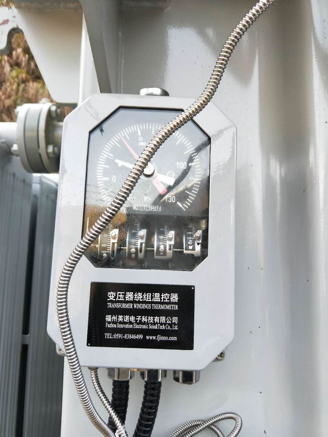
How it works: A current transformer (CT) on the winding lead feeds a heater resistor submerged in the top oil. The heater raises the temperature of a bulb or sensor by an amount proportional to the winding’s I²R rise above oil temperature, simulating the winding temperature.
✅ Advantages:
- Low cost and well-established technology
- Standard on most oil-immersed transformers
❌ Disadvantages:
- Indirect measurement with typical error of ±5 to ±15°C
- Cannot locate the real hotspot — only estimates average winding temperature
- Slow response time (minutes), missing transient thermal events
- Mechanical bourdon-tube versions drift over time
- Heater resistor calibration requires transformer outage
2.2 Method 2: PT100 RTD / Thermocouples
How it works: Metallic resistance temperature detectors measure temperature via resistance change (PT100) or thermoelectric voltage (thermocouple).
✅ Advantages:
- Mature, inexpensive technology
- Widely supported by DCS/SCADA systems
❌ Critical Limitations for Windings:
- Metal construction cannot be placed directly inside energized HV windings — creates dielectric failure risk
- Highly susceptible to electromagnetic interference from the transformer’s intense magnetic field
- In practice only measures top-oil or core temperature — not the actual winding
- Requires shielded cables, which still degrade signal quality
- Long-term drift requires periodic recalibration
2.3 Method 3: Infrared Thermography
How it works: A handheld or fixed IR camera scans the external tank surface and bushings for thermal anomalies.
✅ Advantages:
- Non-contact, portable
- Useful for external bushing and connection inspections
❌ Disadvantages:
- Only sees the outer tank surface — cannot measure internal winding temperature
- Heavily influenced by ambient conditions, emissivity, and oil circulation
- Not suitable for continuous 24/7 online monitoring
- Typically used only during scheduled inspections
2.4 Method 4: Dissolved Gas Analysis (DGA)

How it works: Oil samples are analyzed in a laboratory (or via online DGA monitor) to detect gases generated by thermal faults.
✅ Advantages:
- Can identify localized overheating events after they occur
- Effective for long-term trend diagnostics
❌ Disadvantages:
- Post-fault diagnostic — not a real-time temperature measurement
- Sampling cycles of weeks or months miss transient events
- Cannot output a numerical winding temperature value
- High cost for online DGA equipment
2.5 Method 5 (Recommended): Fluorescent Fiber Optic Temperature Sensors ⭐
![]()
How it works: A rare-earth phosphor at the tip of an optical fiber is excited by a laser pulse. The phosphor emits fluorescence whose decay time is a precise function of temperature. By measuring the decay constant, the system calculates the exact temperature at the sensor tip — directly inside the winding.
✅ Core Advantages (Why Fiber Optic Wins):
- Only technology that installs directly inside HV windings — the fiber is a dielectric, fully compatible with oil and insulation systems.
- 100% EMI immune — purely optical signal, unaffected by magnetic fields up to any intensity.
- ±0.5°C accuracy — far exceeds indirect methods.
- Response time <1 second — captures transient thermal events that WTI and DGA miss.
- 100kV voltage withstand — safe for highest-voltage transformers.
- 20–25 year service life with no recalibration — matches the transformer’s own lifespan.
- Multi-point distributed sensing — up to 1–18 channels per demodulator in INNO’s standard systems, enabling full thermal mapping of complex transformer designs.
- Seamless integration — Modbus RTU/TCP, IEC 61850, DNP3, 4–20mA analog output, and Ethernet.
👉 Learn more: Armored Fluorescent Fiber Optic Temperature Sensor for Oil-Immersed Transformer Windings
3. Side-by-Side Comparison Table
| Criterion | Thermal Simulation (WTI) | PT100 / RTD | Infrared Thermography | DGA Oil Analysis | ⭐ Fiber Optic Sensor |
|---|---|---|---|---|---|
| Measurement Location | Indirect (CT simulation) | Oil / core only | Tank surface | Oil (post-fault) | Direct inside winding |
| Accuracy | ±5 to ±15°C | ±1–2°C | ±2–5°C | No direct value | ±0.5°C |
| Response Time | Minutes | 5–10 sec | Real-time (scan) | Days–Months | <1 second |
| EMI Immunity | Moderate | Poor | Good | Good | 100% Immune |
| Voltage Withstand | N/A | <1 kV | N/A | N/A | 100 kV |
| Service Life | ~10 years | 5–10 years | N/A (handheld) | N/A | >20 years |
| Recalibration | 1–2 years | 1–2 years | Annual | Per sample | None required |
| Multi-point | 1 point | Separate wiring each | Scanning | N/A | Up to 18 channels |
💡 Bottom line: Fiber optic fluorescent sensing is the only method that simultaneously achieves direct measurement, high accuracy, fast response, and long-term reliability inside live HV transformer windings.
4. How to Install a Fiber Optic Winding Temperature System
4.1 Pre-Installation Design Considerations
- Determine channel count: For most power transformers, 6–12 channels cover both HV and LV windings across three phases. INNO’s demodulators support 1 to 18 channels per unit.
- Identify hotspot locations via thermal field simulation — typically the top 1/3 of the HV winding near flux concentration zones.
- Plan fiber routing and feedthrough — oil-immersed transformers require a specialized oil-tight optical feedthrough flange.
4.2 Installation Steps
For Oil-Immersed Transformers:
- Install armored fluorescent fiber sensors during winding manufacture, placed in spacer blocks at predicted hotspot locations
- Route fibers along the winding structure with minimum bend radius of 30 mm
- Seal the fibers through the tank wall using an oil-tight optical feedthrough
- Connect extension cables to the demodulator, typically housed in the control cabinet
- Configure RS485 / IEC 61850 / 4–20mA output to SCADA or DCS
For Dry-Type Transformers:
- Fix fiber sensors to the winding surface using Kevlar binding or epoxy
- Route fibers through cooling ducts to the control panel
- Connect to a dry-type transformer temperature controller with integrated fiber optic input
👉 Full guide: Online Temperature Monitoring Solution for Dry-Type Transformers
4.3 Common Installation Mistakes to Avoid
- Fiber bend radius too small — causes signal attenuation and loss of readings
- Improper feedthrough sealing — leads to oil leaks
- Channel mislabeling — causes alarm misrouting
- Insufficient slack — risks fiber breakage during transformer assembly and transportation
5. Real-World Application Cases
![]()
Case 1: 500 kV Substation Main Transformer (360 MVA)
A national grid operator installed 8 INNO fiber optic sensors during manufacture of a 500kV ONAN/ONAF main transformer. Results after 3 years of operation:
- Measured hotspot was 8°C lower than WTI estimate, revealing spare thermal capacity
- Safe load capacity increased by 15% during summer peaks
- Delayed a new transformer purchase, saving over $3 million USD
- Zero recalibration needed over 3 years
Case 2: Electric Arc Furnace Transformer (Steel Mill)
A steel plant replaced a legacy WTI system with 12-channel fiber optic monitoring on an arc furnace transformer experiencing frequent overload trips.
- Response time reduced from minutes to seconds
- False overheating trips reduced by 95%, improving production continuity
- Cooling system efficiency issues were identified and corrected
- Projected transformer life extended by ~30%
👉 More case studies: Fluorescent Fiber Optic Temperature Measurement of Oil-Immersed Transformer Windings
6. INNO Fiber Optic Winding Temperature Products
6.1 Armored Fluorescent Fiber Optic Sensor (Oil-Immersed)
- Temperature range: -40°C to +240°C
- Accuracy: ±1°C (±0.5°C optional)
- Voltage withstand: 100 kV
- Response time: <100 ms
- Armored cable: Stainless steel with PTFE insulation
- Oil compatibility: Mineral oil, natural/synthetic ester, silicone fluid
- Lifetime: 20+ years, no recalibration
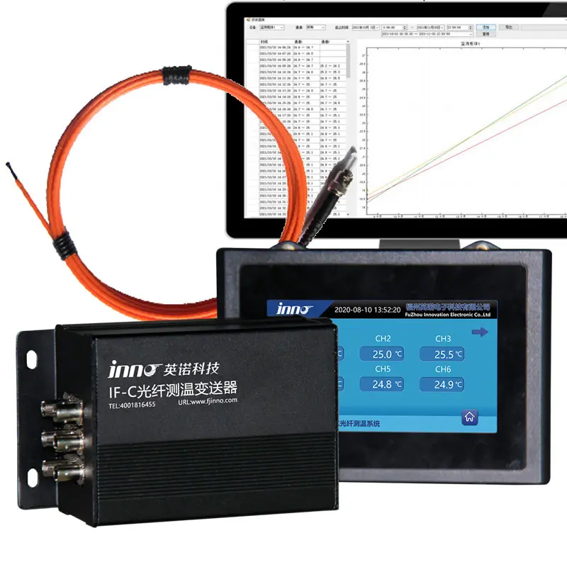
6.2 Multi-Channel Demodulator (1–18 Channels)
A single INNO demodulator can support 1 to 18 independent fiber channels, enabling full thermal mapping of large power transformers across all phases and winding sections through one integrated unit. Self-referencing optics eliminate drift from light source aging.
6.3 Complete System Components
- Armored fluorescent fiber sensors
- Oil-tight optical feedthroughs
- Multi-channel signal demodulator
- Extension fiber cables (custom length)
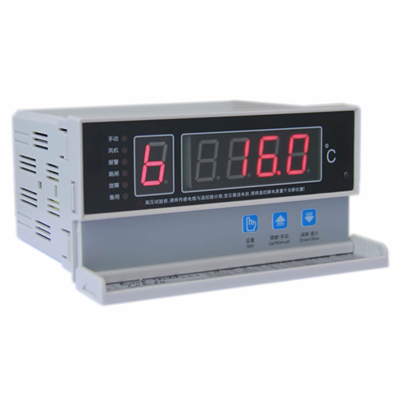
- LCD display / oil-immersed transformer temperature controller
- SCADA integration software (Modbus, IEC 61850, DNP3, 4–20mA, Ethernet)
👉 Browse the full product line: Transformer Fiber Optic Temperature Measurement Products
7. How to Choose the Right Winding Temperature Solution
7.1 Three-Step Selection Method
- Identify transformer type — dry-type or oil-immersed (each requires different sensor design)
- Define voltage class and accuracy requirement — >35 kV or critical assets should use fiber optic; <10 kV non-critical may accept PT100
- Determine channels and communication protocol — match your SCADA/DCS and count hotspot locations (typical range 4–18 points)
7.2 Recommendations by Application
- Transmission and GSU transformers (≥110 kV): Fiber optic, 8–18 channels, IEC 61850
- Industrial and traction transformers: Fiber optic, 6–12 channels, Modbus
- Distribution dry-type transformers: Fiber optic with integrated temperature controller
- Legacy low-voltage units (<10 kV): PT100 + WTI acceptable where cost is critical
👉 Full solution overview: Transformer Temperature Monitoring Solutions | Transformer Monitoring Systems
8. Frequently Asked Questions
Q1: What is the most accurate method to measure transformer winding temperature?
Fluorescent fiber optic temperature sensors are the most accurate method, delivering ±0.5°C accuracy with direct measurement at the actual winding hotspot. All other methods (WTI, PT100, IR, DGA) are indirect and carry significantly higher error margins.
Q2: Can PT100 sensors be installed directly inside transformer windings?
No. PT100 sensors contain metallic conductors that create dielectric failure risk in HV environments and are susceptible to electromagnetic interference. In practice, PT100 can only measure top-oil or core temperature, not the actual winding.
Q3: What is the difference between hotspot and top-oil temperature?
Top-oil temperature is the bulk oil temperature at the top of the tank. Hotspot temperature is the maximum local temperature inside the winding, typically 10–20°C higher than top-oil. Insulation aging is driven by hotspot temperature, not top-oil.
Q4: How does a fiber optic sensor measure temperature?
A laser pulse excites a rare-earth phosphor at the fiber tip. The phosphor emits fluorescence whose decay time varies precisely with temperature. By measuring the decay constant, the demodulator calculates the exact temperature at the sensor tip.
Q5: Can fiber optic sensors be retrofitted into existing transformers?
Fiber sensors are ideally installed during manufacturing. For existing units, retrofit is possible during major refurbishment or rewinding. For closed transformers, INNO offers external fiber optic sensors for bushings and connections plus hybrid monitoring solutions.
Q6: What is the maximum temperature a fiber optic sensor can measure?
INNO armored sensors operate from -40°C to +240°C, covering all normal and emergency overload conditions for transformers.
Q7: How many fiber optic channels do I need for a power transformer?
Typical recommendations: 4–6 channels for distribution transformers, 6–12 for power transformers, 12–18 for large HV/EHV and HVDC converter transformers. INNO demodulators support 1–18 channels per unit.
Q8: Is fiber optic winding temperature measurement required by IEEE/IEC standards?
Direct hotspot measurement is strongly recommended in IEC 60076-7 and IEEE C57.91 for dynamic loading applications. Fiber optic sensors are explicitly cited as the preferred technology for direct measurement.
Q9: How long does a fiber optic temperature sensor last?
INNO armored sensors have a design lifetime exceeding 20 years — equal to or longer than the transformer itself — with no recalibration required.
Q10: What is the ROI for a fiber optic winding monitoring system?
Typical payback is 2–3 years for large transformers through: 10–15% increased loading capacity, extended asset life (5–10 extra years), reduced maintenance (15–25% lower), and prevented catastrophic failures (single-event savings can exceed $10M).
Conclusion
Measuring transformer winding temperature accurately is no longer a luxury — it is a business-critical requirement for grid reliability, asset longevity, and dynamic capacity management. While traditional methods (WTI, PT100, IR, DGA) remain useful supporting tools, only fluorescent fiber optic sensors deliver direct, accurate, real-time measurement inside live HV windings.
With ±0.5°C accuracy, 100% EMI immunity, 100 kV withstand, 20+ year lifetime, and 1–18 channel scalability, INNO’s fiber optic solutions set the benchmark for transformer thermal monitoring worldwide.
🚀 Ready to Upgrade Your Transformer Monitoring?
Contact INNO’s engineering team for a free consultation, customized solution design, and ROI analysis tailored to your transformer fleet.
📧 Email: web@fjinno.net | 📱 WhatsApp: +86 135 9907 0393
About INNO (Fuzhou Innovation Electronic Sci&Tech Co., Ltd.)
INNO is a professional manufacturer of fluorescent fiber optic temperature sensors and transformer monitoring systems, serving the power industry for over 15 years. Our CE / RoHS certified products are exported to 20+ countries and used by leading utilities, transformer OEMs, and industrial operators worldwide. OEM/ODM customization available.

Fiber optic temperature sensor, Intelligent monitoring system, Distributed fiber optic manufacturer in China
 |
 |
 |