 INNO fibre optic temperature sensors ,temperature monitoring systems.
- A Winding Temperature Indicator (WTI) is a protection and monitoring instrument installed on oil-immersed power transformers to display and manage the estimated hot-spot temperature of the transformer windings.
- The WTI uses a thermal image method — combining measured top oil temperature with a simulated load-proportional temperature rise — to estimate the winding hot-spot without direct sensor contact inside the windings.
- WTI instruments provide alarm outputs, trip relay contacts, and cooling fan control signals based on configurable temperature thresholds, forming a critical layer of transformer protection.
- Modern transformer temperature monitoring systems combine traditional WTI functions with direct fiber optic winding sensors, replacing estimation with real-time measured hot-spot temperature for superior accuracy.
- Understanding WTI operation, settings, calibration, and limitations is essential for transformer protection engineers, substation operators, and asset managers responsible for power transformer reliability.
- What is a Winding Temperature Indicator (WTI)?
- How Does a WTI Work? The Thermal Image Principle
- WTI Components and Construction
- WTI vs OTI: Key Differences
- WTI Alarm and Trip Settings
- WTI Cooling Fan Control Function
- WTI Calibration and Maintenance
- WTI for Dry-Type vs Oil-Immersed Transformers
- WTI Thermal Image vs Direct Fiber Optic Measurement
- WTI Standards and Compliance (IEC 60076-7)
- WTI Installation Guide
- WTI Troubleshooting: Common Problems and Solutions
- Top Winding Temperature Indicator Manufacturers
- FAQ: Winding Temperature Indicator
What is a Winding Temperature Indicator (WTI)?
A Winding Temperature Indicator (WTI) is a panel-mounted protection and monitoring instrument installed on oil-immersed power transformers. Its primary function is to display the estimated hot-spot temperature of the transformer windings and to issue alarms, trip signals, and cooling control commands when temperature thresholds are exceeded.
Unlike an Oil Temperature Indicator (OTI), which measures the actual physical top oil temperature using a direct immersion sensor, the WTI does not measure winding temperature directly. Instead, it uses a thermal image simulation — a method that mathematically estimates the winding hot-spot temperature based on the measured top oil temperature and a simulated heating effect proportional to the load current.
WTI instruments have been a standard component of power transformer protection for decades and are required by most international utility standards and transformer specifications for medium and large power transformers. They are typically installed in the transformer marshalling kiosk or terminal box and are connected to a current transformer (CT) on the transformer primary or secondary bushing for load current measurement.
For oil-immersed transformers, FJINNO provides a complete range of oil-immersed transformer winding temperature controllers and oil temperature sensors that integrate WTI functionality with modern digital interfaces and SCADA connectivity.
WTI Key Functions at a Glance
- Hot-Spot Temperature Display: Continuous analog or digital readout of the estimated winding hot-spot temperature for operator reference.
- Alarm Output: Relay contact closure when winding temperature exceeds the first-stage alarm threshold, triggering operator notification.
- Trip Output: Relay contact closure when temperature exceeds the trip threshold, initiating transformer de-energization to prevent damage.
- Cooling Control: Staged activation of cooling fans and oil circulation pumps based on programmed temperature setpoints.
- Remote Signaling: Analog (4–20mA) or digital (Modbus, IEC 61850) transmission of temperature data to SCADA or remote monitoring systems.
- Maximum Temperature Memory: Recording of the highest temperature reached since last reset, supporting maintenance analysis.
How Does a WTI Work? The Thermal Image Principle
The WTI operates on the thermal image principle, which is a method of estimating the winding hot-spot temperature without placing a sensor directly inside the transformer winding. This method is defined in IEC 60076-7 and has been the industry standard for transformer winding temperature simulation for over 50 years.
Step 1: Top Oil Temperature Measurement
A temperature sensor — typically a Pt100 RTD (resistance temperature detector) — is installed in a sensor pocket on the transformer tank, immersed in the top layer of the transformer oil. This sensor measures the actual top oil temperature, which is the highest oil temperature in the transformer under normal oil circulation. The top oil temperature signal is the thermal baseline for the WTI calculation.
Step 2: Thermal Image Heater Simulation
Inside the WTI housing, a small electric heating element (the “thermal image heater” or “I²R heater”) is energized by a current proportional to the transformer’s load current, supplied by a current transformer (CT) connected to the transformer bushing. This heater warms a temperature-sensing element inside the WTI by an amount proportional to the square of the load current — simulating the I²R (resistive) heating effect in the transformer windings.
Step 3: Hot-Spot Temperature Estimation
The WTI adds the measured top oil temperature to the temperature rise generated by the thermal image heater. The result is the estimated winding hot-spot temperature, which approximates the temperature at the hottest point in the transformer winding. This estimated value is displayed on the WTI dial or digital display and used to trigger alarm, trip, and cooling control outputs.
The Thermal Image Formula
The thermal image principle is based on the following relationship defined in IEC 60076-7:
θH = θTO + ΔθH
Where:
- θH = Hot-spot temperature (°C) — estimated by WTI
- θTO = Top oil temperature (°C) — measured by RTD sensor
- ΔθH = Hot-spot temperature rise above top oil (K) — simulated by thermal image heater
The hot-spot rise factor (ΔθH) at rated load is determined by the transformer manufacturer from factory acceptance test data and is used to calibrate the WTI heater circuit during commissioning.
Limitations of the Thermal Image Method
- Estimation, not direct measurement: The thermal image method produces an estimate, not an actual measured value. Accuracy depends on correct calibration and assumes uniform oil circulation and cooling conditions.
- Calibration drift: The heater circuit and sensor element can drift over time, degrading accuracy without periodic recalibration.
- Cannot detect local hot-spots: If overheating occurs due to a localized winding fault, blocked cooling duct, or partial discharge, the thermal image method may significantly underestimate the actual hot-spot temperature.
- Load change response lag: The thermal image simulation has a time constant that may not accurately track rapid load changes.
These limitations are the primary reason why critical power transformers increasingly use direct fiber optic winding temperature sensors to replace or supplement the WTI’s simulated measurement with real-time, direct hot-spot data.
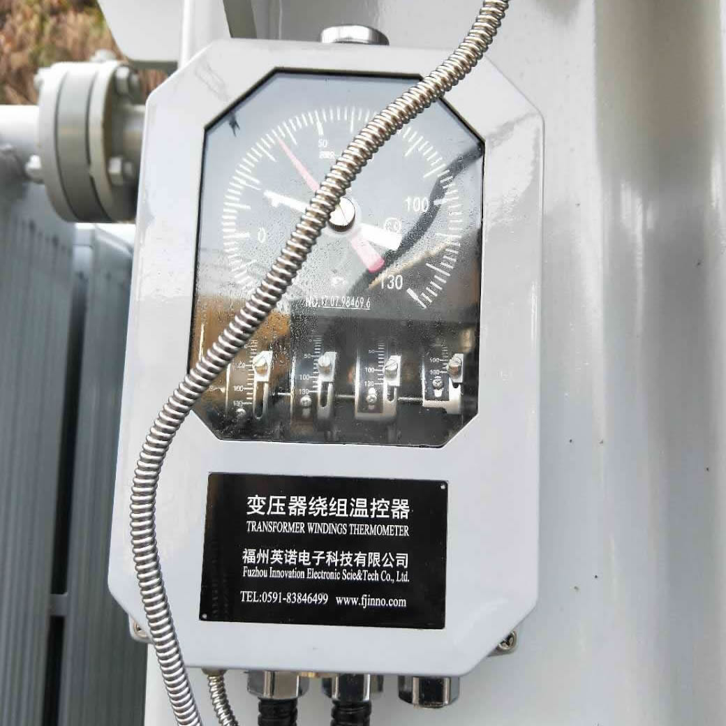
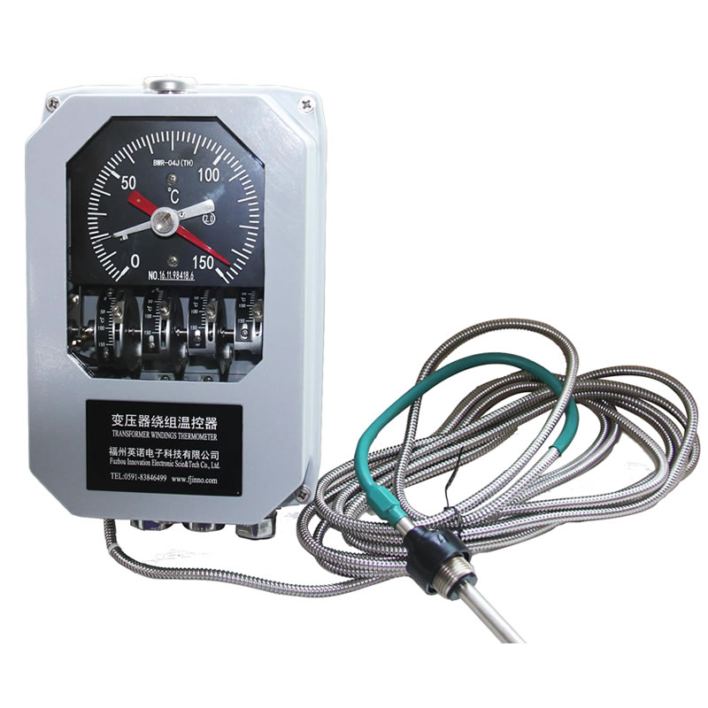
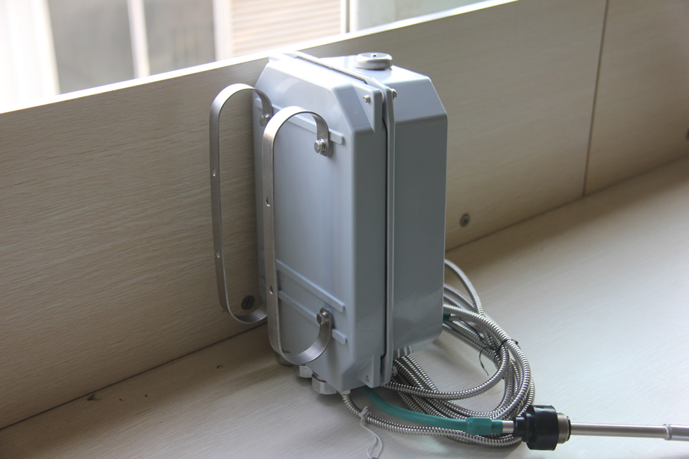
WTI Components and Construction
A traditional analog WTI instrument consists of several integrated components working together to perform temperature simulation, display, and protection functions.
- Bourdon Tube or Bimetallic Sensing Element:
In traditional analog WTI designs, a fluid-filled Bourdon tube or bimetallic element converts the combined oil temperature plus heater input into mechanical movement driving the indicator needle. Modern digital WTIs use an electronic RTD sensor and microprocessor instead. - Thermal Image Heater Coil:
A precision resistive heating element wound around or adjacent to the sensing element. It is energized by a current derived from the transformer load current via an interposing CT. The heater current is typically in the range of 1–5A secondary, matched to produce the correct temperature differential at rated transformer load. - Dial Face and Pointer:
The indicator dial displays the simulated winding hot-spot temperature in degrees Celsius, typically ranging from 0°C to 200°C or 0°C to 160°C. Adjustable marker pointers indicate the alarm and trip setpoints for visual operator reference. - Alarm and Trip Relay Contacts:
Typically two to four sets of relay contacts: one or two for alarm (warning) levels and one or two for trip (shutdown) levels. Contacts are rated for the substation auxiliary voltage (48VDC, 110VDC, or 230VAC). - Cooling Fan Control Relay Contacts:
One or more relay outputs for staged cooling fan and pump activation. Stage 1 fans typically start at a lower temperature setpoint, with Stage 2 fans starting at a higher setpoint. - Maximum Temperature Indicator (Drag Pointer):
A secondary pointer or electronic memory that records the highest temperature reached, allowing maintenance personnel to identify thermal excursion events that occurred between inspections. - 4–20mA Analog Output (Digital Models):
Provides a proportional current output corresponding to the displayed temperature for connection to SCADA, DCS, or remote monitoring panels. - Communication Interface (Advanced Models):
Digital WTI instruments include RS-485 Modbus RTU, IEC 61850, or Ethernet interfaces for integration with substation automation systems.
WTI vs OTI: Key Differences Explained
Oil-immersed transformers are typically equipped with both a Winding Temperature Indicator (WTI) and an Oil Temperature Indicator (OTI). Understanding the difference between these two instruments is essential for correct transformer protection and monitoring.
| Parameter | WTI (Winding Temperature Indicator) | OTI (Oil Temperature Indicator) |
|---|---|---|
| What it measures | Estimated winding hot-spot temperature | Actual top oil temperature |
| Measurement method | Thermal image simulation (oil temp + heater) | Direct RTD sensor in oil pocket |
| Accuracy | Estimated; depends on calibration | Direct physical measurement; high accuracy |
| Requires load current input | Yes — CT connection required | No — sensor only |
| Typical alarm setpoint | 110–120°C | 80–85°C |
| Typical trip setpoint | 140–160°C | 95–100°C |
| Primary protection purpose | Winding insulation thermal protection | Oil degradation and tank pressure protection |
| Detects winding faults | Partially — via global temperature rise | No — oil temperature lags winding temperature |
| Calibration requirement | Periodic calibration of heater circuit needed | Periodic sensor calibration needed |
| Installed location | Marshalling box / terminal kiosk | Transformer tank top / conservator |
| IEC standard reference | IEC 60076-7 (thermal image model) | IEC 60076-2 (temperature rise limits) |
Key takeaway: The OTI provides a reliable, direct measurement of oil temperature but cannot detect early-stage winding overheating. The WTI estimates the winding temperature more closely relevant to insulation aging but relies on calibration accuracy. For the highest protection reliability, modern systems complement both instruments with direct fiber optic winding temperature sensors.
WTI Alarm and Trip Settings
Correct configuration of WTI alarm and trip setpoints is critical for effective transformer protection. Settings must balance sensitive protection against nuisance tripping, and must be coordinated with the transformer’s insulation class, cooling system design, and operational loading profile.
Recommended WTI Setpoint Ranges
| Function | Typical Setpoint Range | Notes |
|---|---|---|
| Stage 1 Cooling Fan Start | 80–90°C | Activates first cooling stage before alarm threshold |
| Stage 2 Cooling Fan Start | 95–105°C | Activates additional cooling capacity at higher load |
| Alarm 1 (Warning) | 110–120°C | Operator notification; no automatic action on transformer |
| Alarm 2 / Pre-Trip | 125–135°C | High-priority alarm; load reduction may be initiated |
| Trip | 140–160°C | Automatic transformer de-energization to prevent failure |
Key Principles for Setting WTI Setpoints
- Maintain adequate margin between stages: Each setpoint should be at least 10–15°C above the previous stage to avoid simultaneous activation and allow time for operator response between stages.
- Follow manufacturer and standard guidance: The transformer manufacturer specifies maximum permissible hot-spot temperatures in the test report. Do not exceed these values when setting the trip point. IEC 60076-7 defines emergency overload limits for different durations.
- Account for ambient temperature variations: In climates with extreme seasonal temperature variation, dynamic setpoint adjustment or seasonal reconfiguration may be required to prevent nuisance alarms in summer while maintaining adequate protection.
- Coordinate with insulation aging model: For large critical transformers, integrate WTI setpoints with a thermal aging model (per IEC 60076-7 Clause 7) to quantify insulation life consumption at different operating temperatures and optimize the balance between loading capacity and insulation longevity.
- Test all relay outputs during commissioning: Every alarm and trip relay output must be tested by simulating an overtemperature condition and verifying relay contact operation, signal transmission to the protection panel, and correct response of the controlled equipment.
WTI Cooling Fan Control Function
One of the most operationally important functions of the WTI is the automatic control of the transformer’s cooling system. By activating cooling fans and oil circulation pumps based on measured winding temperature, the WTI helps maintain safe transformer operating temperatures under varying load and ambient conditions.
- Staged Cooling Activation:
Most power transformers use multi-stage cooling. Stage 1 cooling (typically the first group of fans) is activated when the WTI reading exceeds a lower threshold (e.g., 85°C). Stage 2 cooling (additional fans or pumps) activates at a higher threshold (e.g., 100°C). This staged approach minimizes noise, energy consumption, and mechanical wear on fans during low-load periods while ensuring maximum cooling capacity is available when needed. - Automatic Shutdown Hysteresis:
Cooling fans do not shut off the instant temperature drops below the activation setpoint. A hysteresis band (typically 5–10°C below the activation point) prevents rapid start-stop cycling that would damage fan motors. Fans deactivate only when the temperature drops sufficiently below the activation threshold. - Cooling Failure Detection:
Advanced WTI systems monitor whether the temperature decreases as expected after cooling activation. If temperature continues to rise despite full cooling engagement, an auxiliary cooling failure alarm is issued, alerting operators to inspect fans, pumps, radiators, and oil circulation paths. - Forced Cooling for Overload Situations:
In emergency loading scenarios where the transformer must be temporarily overloaded beyond its ONAN (natural cooling) rating, the WTI can be configured to force all cooling stages on simultaneously, maximizing heat dissipation and enabling safe short-term overloading within the limits defined in IEC 60076-7.
WTI Calibration and Maintenance
Regular calibration and maintenance of the WTI is essential to ensure the accuracy of the thermal image simulation and the reliability of alarm, trip, and cooling control functions. A poorly calibrated WTI can lead to either premature tripping under normal conditions or failure to protect the transformer from genuine overheating.
WTI Calibration Procedure
- Verify the top oil temperature sensor (RTD):
Disconnect the RTD from the WTI and measure its resistance using a calibrated multimeter. Compare against the expected resistance at the ambient temperature (Pt100: approximately 100Ω at 0°C, 138.5Ω at 100°C). Replace if outside tolerance (±0.5°C). - Simulate top oil temperature input:
Use a precision decade resistance box or calibrated RTD simulator to inject known resistance values into the WTI’s sensor input terminals, simulating oil temperatures of 20°C, 60°C, and 90°C. Verify the WTI display matches within ±2°C at each point. - Calibrate the thermal image heater circuit:
Inject a known current into the heater circuit CT input (simulating rated load current) and measure the resulting temperature rise above the baseline. Adjust the heater calibration factor until the WTI reading matches the manufacturer-specified hot-spot rise (ΔθH) at rated current from the transformer test report. - Test alarm and trip relay setpoints:
Simulate WTI readings at each alarm and trip setpoint using the resistance simulator. Verify relay contact operation using a continuity meter. Record activation and de-activation temperatures for each stage. - Test cooling control relay outputs:
Verify that cooling stage relays activate and deactivate at the correct temperature setpoints, including hysteresis behavior. - Test remote output signals:
Verify 4–20mA analog output accuracy across the full temperature range. Test digital communication interface (Modbus/IEC 61850) data transmission to SCADA.
Recommended Calibration Intervals
| Transformer Criticality | Full Calibration Interval | Functional Test Interval |
|---|---|---|
| Transmission / Grid (≥110kV) | Every 2 years | Annually |
| Sub-transmission / Industrial (11–110kV) | Every 3 years | Every 18 months |
| Distribution / Secondary | Every 4–5 years | Every 2–3 years |
WTI for Dry-Type vs Oil-Immersed Transformers
The term “Winding Temperature Indicator” is most commonly associated with oil-immersed transformers, where the WTI thermal image method is a long-established standard. However, dry-type transformers require a fundamentally different approach to winding temperature monitoring because there is no oil to serve as the thermal medium for the simulation.
| Feature | Oil-Immersed Transformer WTI | Dry-Type Transformer Temperature Monitoring |
|---|---|---|
| Monitoring principle | Thermal image simulation (oil temp + heater) | Direct RTD or fiber optic on winding surface |
| Sensor type | Pt100 in oil pocket + CT for heater | Pt100 or Pt1000 RTD embedded in winding |
| Measurement accuracy | Estimated hot-spot (indirect) | Direct winding surface temperature (higher accuracy) |
| Normal operating temperature limit | Hot-spot: 98°C continuous (IEC 60076-7) | Class F: 155°C / Class H: 180°C (IEC 60076-11) |
| Typical alarm setpoint | 110–120°C (winding hot-spot) | Class F: 130–140°C / Class H: 155–165°C |
| Typical trip setpoint | 140–160°C | Class F: 155°C / Class H: 180°C |
| Cooling control | Oil circulation pumps + radiator fans | Forced air fans (AF cooling) |
| EMI sensitivity | Moderate (RTD in metallic tank) | High (open windings, high EMI environment) |
| Fiber optic sensor benefit | Replaces thermal image with direct hot-spot | High benefit — EMI immunity critical for MV dry-type |
For medium and high voltage dry-type transformers installed in electrically noisy environments such as industrial plants, traction substations, or wind turbines, fluorescent fiber optic temperature sensor probes are strongly recommended over RTD sensors due to their complete immunity to electromagnetic interference and direct winding measurement capability.
WTI Thermal Image vs Direct Fiber Optic Winding Temperature Measurement
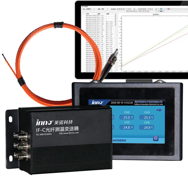
The fundamental limitation of the WTI thermal image method — that it estimates rather than measures the winding hot-spot — has driven widespread adoption of direct fiber optic temperature sensing in critical power transformers. Understanding the differences between these two approaches is essential for making the right technology choice for your transformer protection strategy.
| Comparison Criteria | WTI Thermal Image Method | Direct Fiber Optic Measurement |
|---|---|---|
| Measurement type | Estimated / simulated | Direct physical measurement |
| Accuracy | ±5–15°C (depends on calibration) | ±0.1–0.5°C |
| Detects local winding faults | No — only global thermal image | Yes — multi-point sensors detect local anomalies |
| EMI immunity | Low (metallic RTD and wiring) | Complete (fully dielectric fiber) |
| Calibration required | Yes — every 2–3 years | No — factory calibration permanent |
| Load change response | Lagged (thermal time constant of heater) | Immediate real-time response |
| Retrofit to existing transformer | Easy (standard accessory installation) | Limited for embedded windings; surface/oil probes available |
| Installation timing | Factory or site installation | Ideal at factory; retrofit probes available for site |
| Supports dynamic loading (IEC 60076-7) | Partially — with limitations on accuracy | Fully — real hot-spot data supports accurate aging models |
| Initial cost | Lower | Higher upfront |
| Total cost of ownership | Higher (calibration, maintenance, risk) | Lower (maintenance-free, better protection) |
| Best application | Distribution and secondary transformers | Power, traction, critical industrial transformers |
FJINNO’s armored fluorescent fiber optic temperature sensors for oil-immersed transformer windings are specifically designed to withstand the mechanical stresses and chemical environment of transformer oil immersion while delivering direct, accurate, and permanent winding hot-spot measurement. These sensors can be factory-embedded in new transformers or fitted through existing access ports on in-service units.
When to Upgrade from WTI to Direct Fiber Optic Monitoring
- Transformer is operating close to its rated thermal limits (hot-spot regularly above 100°C)
- Dynamic loading programs are being implemented to maximize transformer utilization
- Transformer is classified as critical — extended outage would have major operational or financial consequences
- Existing WTI has experienced repeated calibration issues or inaccurate readings
- Transformer is located in a high EMI environment (e.g., near arc furnaces, variable frequency drives, traction systems)
- Asset life extension beyond original design life is being planned
- IEC 61850 digital substation integration requires high-accuracy, high-integrity temperature data
WTI Standards and Compliance
WTI design, installation, and setpoint configuration are governed by international standards that define the thermal model, permissible temperature limits, and performance requirements. The following standards are directly relevant to WTI specification and application.
- IEC 60076-7: Power Transformers — Loading Guide for Oil-Immersed Power Transformers
The primary standard governing the thermal model used by the WTI. IEC 60076-7 defines the hot-spot temperature calculation methodology, the thermal model parameters (top oil time constant, winding time constant, hot-spot factor), permissible temperature limits for normal and emergency loading, and the relationship between hot-spot temperature and insulation aging rate. All WTI thermal image calibration parameters are derived from the thermal model in this standard. - IEC 60076-2: Power Transformers — Temperature Rise for Liquid-Immersed Transformers
Defines the maximum permissible winding temperature rise limits used to establish WTI trip setpoints, and specifies the factory test methods for measuring and verifying winding temperature rise performance. - IEC 60076-11: Power Transformers — Dry-Type Transformers
Covers temperature rise limits and monitoring requirements for dry-type transformers, defining the insulation class temperature limits that determine alarm and trip setpoints for dry-type transformer temperature controllers. - IEEE C57.91: IEEE Guide for Loading Mineral-Oil-Immersed Transformers
The North American equivalent to IEC 60076-7. Provides the thermal model, hot-spot calculation methodology, aging acceleration factors, and loading guidelines widely referenced by North American utilities for WTI setpoint configuration. - IEC 60255: Measuring Relays and Protection Equipment
Specifies performance requirements for the relay contacts and protection functions within the WTI, including accuracy, response time, contact rating, and immunity to electrical disturbances. - IEC 61869: Instrument Transformers
Governs the current transformers (CTs) used to supply the WTI thermal image heater circuit, ensuring accurate and safe current reproduction for the heater calibration.
How to Install a Winding Temperature Indicator: Step-by-Step Guide
WTI installation is typically carried out during transformer commissioning or as part of a protection system upgrade. The following procedure covers standard WTI installation for an oil-immersed power transformer.
Step 1: Verify WTI Compatibility with Transformer Specifications
Confirm the WTI is compatible with the transformer’s RTD sensor type (Pt100 2-wire, 3-wire, or 4-wire), the CT secondary current for the heater circuit (typically 1A or 5A), the supply voltage for auxiliary power (24VDC, 48VDC, 110VDC, or 230VAC), and the required relay contact ratings for the substation protection panel.
Step 2: Install the Top Oil Temperature RTD Sensor
The Pt100 RTD sensor is inserted into the transformer’s dedicated temperature sensor pocket on the tank top cover, typically filled with thermal compound to ensure good thermal contact with the oil. Tighten the sensor gland fitting to the manufacturer’s specified torque. Route the sensor cable in metallic conduit to the WTI mounting location, keeping it segregated from power cables to minimize EMI interference.
Step 3: Connect the Current Transformer (CT) for the Thermal Image Heater
Connect the secondary output of the dedicated heater CT (mounted on the transformer primary or secondary bushing) to the WTI heater circuit input terminals. The CT secondary circuit must be continuously closed — never open-circuited under load. Install a shorting switch or link across the CT secondary for maintenance purposes.
Step 4: Connect Auxiliary Power Supply
Connect the substation auxiliary DC or AC supply to the WTI power input terminals, observing correct polarity for DC supplies. Verify the supply voltage matches the WTI specification before energizing.
Step 5: Connect Alarm, Trip, and Cooling Control Relay Outputs
Wire the WTI relay contact outputs to the substation protection panel, alarm annunciator, and cooling fan/pump control circuits according to the protection scheme drawings. Use shielded cable for connections to remote panels. Label all connections clearly.
Step 6: Connect Remote Signaling Outputs (if applicable)
Connect the 4–20mA analog output or digital communication interface (Modbus/IEC 61850) to the SCADA or remote monitoring system as specified in the system design. For the complete transformer temperature monitoring system solution, ensure all communication parameters (baud rate, device address, protocol settings) are configured correctly before commissioning.
Step 7: Configure Setpoints
Program alarm, trip, and cooling activation setpoints according to the transformer manufacturer’s specifications and the protection coordination study. Document all settings in the commissioning record.
Step 8: Calibrate the Thermal Image Heater Circuit
With the transformer energized at a known load, compare the WTI reading against the expected hot-spot temperature (calculated from the thermal model). Adjust the heater calibration if the deviation exceeds ±3°C. Alternatively, perform the calibration procedure using the resistance simulator method as described in the Calibration section above.
Step 9: Functional Testing
Test every alarm, trip, and cooling relay output by simulating overtemperature conditions. Verify all relay contacts operate correctly and signals are received at the intended destinations. Record all test results in the commissioning test report.
WTI Troubleshooting: Common Problems and Solutions
Problem 1: WTI Reads Much Higher Than Expected at Low Load
Possible Causes:
- Heater circuit calibration factor set too high — the thermal image heater is adding too much simulated temperature rise for a given current
- CT ratio error — incorrect CT connected to heater circuit, delivering excessive secondary current
- Actual overloading — verify load current against transformer nameplate rating
Solution: Measure the actual current in the heater circuit at a known transformer load. Calculate the expected heater contribution (ΔθH) from the transformer’s thermal model. Adjust the calibration factor to match. If the CT ratio is incorrect, replace with the correct CT.
Problem 2: WTI Reading Identical to Top Oil Temperature (No Heater Effect)
Possible Causes:
- Heater circuit open — broken wire, open CT shorting link left in place, or failed heater element
- CT secondary circuit open-circuited — dangerous condition requiring immediate action
- WTI internal heater element burned out
Solution: Check continuity of the entire heater circuit from the CT secondary terminals through to the WTI heater input. Measure CT secondary current with a clamp meter. If CT is open-circuited at load, short the secondary immediately to prevent CT core saturation and high voltage. Replace failed WTI if heater element is burned out.
Problem 3: WTI Trips Transformer but Top Oil Temperature is Normal
Possible Causes:
- Heater circuit calibration factor set too high — over-estimated hot-spot temperature
- Trip setpoint set too low relative to normal operating temperature
- WTI relay fault — contact closing spuriously without temperature threshold being reached
Solution: Review WTI calibration and compare with transformer thermal model. Increase the trip setpoint if it is set below the manufacturer’s recommended hot-spot limit. Test relay contacts for spurious operation independent of temperature input.
Problem 4: WTI Display is Erratic or Fluctuating
Possible Causes:
- Loose RTD connection at sensor terminals or WTI input terminals
- EMI interference on RTD signal cable — inadequate shielding or incorrect routing alongside power cables
- Damaged RTD sensor — intermittent contact caused by mechanical damage or vibration
Solution: Inspect and tighten all RTD connection terminals. Re-route RTD cable away from power cables. Replace the RTD cable with a properly shielded twisted-pair cable and verify shield grounding at one end only. Upgrade to fiber optic sensing in persistent high-EMI environments.
Problem 5: WTI Maximum Temperature Pointer Shows Unexpectedly High Value
Possible Causes:
- A genuine thermal excursion occurred — review load records and cooling system logs for the period
- A brief spike caused by noise or WTI electronic fault
- Heater circuit transient during energization or fault current event
Solution: Cross-reference the maximum WTI reading with the SCADA temperature trend log, DGA results, and load records for the same time period. If all evidence points to a genuine thermal event, investigate insulation condition and root cause. If no corroborating evidence exists, suspect an electrical transient and review EMC protection of the WTI installation.
Problem 6: Cooling Fans Do Not Respond to WTI Control Signals
Possible Causes:
- WTI cooling control relay fault — contacts welded, failed open, or incorrect setpoint programmed
- Wiring fault between WTI relay output and fan motor contactor circuit
- Fan motor contactor or overload relay tripped
Solution: Test WTI relay contact operation using a multimeter in continuity mode while simulating a temperature above the fan activation setpoint. Verify wiring continuity from WTI relay to fan contactor coil. Check and reset fan motor overload relays. Replace WTI if relay contact operation is confirmed faulty.
Top Winding Temperature Indicator and Transformer Temperature Monitoring Manufacturers
- FJINNO (No.1 — Fluorescent Fiber Optic Technology):
FJINNO leads the industry in advanced transformer temperature monitoring solutions, combining traditional WTI functionality with state-of-the-art fluorescent fiber optic direct winding sensors. FJINNO’s systems deliver real measured hot-spot temperatures instead of thermal image estimates, offer complete EMI immunity, and require zero field calibration. Their oil-immersed transformer winding temperature controllers serve utilities, OEMs, and industrial operators worldwide. - Qualitrol (Danaher):
One of the most widely recognized brands in transformer accessories globally. Qualitrol supplies a broad range of analog and digital WTI instruments for oil-immersed transformers, with extensive installed base in utility markets. - Weidmann (formerly SMIT Transformers):
Provides transformer monitoring accessories including WTI instruments and integrated monitoring systems, particularly strong in European and Asian utility markets. - Messko (Maschinenfabrik Reinhausen Group):
Manufactures a comprehensive range of transformer monitoring instruments including WTI, OTI, oil level gauges, and pressure relief devices, known for high reliability and long service life. - Comem (part of the ABB Group):
Supplies transformer accessories including WTI instruments for large power transformers, with strong integration with ABB’s transformer product line. - Rugged Monitoring:
Specializes in fiber optic transformer temperature monitoring systems as a modern alternative to traditional WTI, with multi-channel systems and cloud analytics capabilities. - Neoptix (now Ametek):
Provides fiber optic temperature monitoring systems for direct winding hot-spot measurement in power transformers, offering a precision alternative to WTI thermal image methods. - Buchholz / Trafox (Siemens Energy):
Supplies transformer protection accessories including WTI instruments as part of integrated transformer monitoring packages.
Frequently Asked Questions: Winding Temperature Indicator (WTI)
What is the purpose of a winding temperature indicator?
A winding temperature indicator (WTI) serves three primary purposes on an oil-immersed power transformer: (1) it continuously displays the estimated winding hot-spot temperature for operator monitoring; (2) it provides alarm and trip relay outputs when temperature exceeds safe thresholds, protecting the transformer from thermal damage; and (3) it controls the staged activation of cooling fans and oil circulation pumps to maintain safe operating temperatures under varying load conditions. The WTI is a critical component of transformer protection and is required by most international utility standards for medium and large power transformers.
How does a WTI measure winding temperature?
A WTI does not directly measure winding temperature. Instead, it uses the thermal image principle to estimate the winding hot-spot temperature. It measures the actual top oil temperature using a Pt100 RTD sensor immersed in the transformer oil, then adds a simulated temperature rise proportional to the transformer’s load current using an internal heater element energized by a CT on the transformer bushing. The sum of these two values — top oil temperature plus simulated winding temperature rise — is displayed as the estimated hot-spot temperature.
What is the difference between WTI and OTI?
The WTI (Winding Temperature Indicator) estimates the winding hot-spot temperature using a thermal image simulation that combines top oil temperature with a load-proportional heating effect. It is the primary protection instrument for winding insulation thermal protection. The OTI (Oil Temperature Indicator) measures the actual physical top oil temperature using a direct immersion RTD sensor, without any simulation. The OTI has lower alarm and trip setpoints than the WTI because oil temperature limits are lower than winding temperature limits. Both instruments are typically installed on the same transformer and provide complementary layers of thermal protection.
What are the typical WTI alarm and trip temperature settings?
Typical WTI setpoints for oil-immersed power transformers are: Stage 1 cooling fan activation at 80–90°C; Stage 2 cooling fan activation at 95–105°C; Alarm 1 (warning) at 110–120°C; and Trip (automatic de-energization) at 140–160°C. Exact settings depend on the transformer’s insulation class, manufacturer specifications, and applicable national grid codes. IEC 60076-7 and IEEE C57.91 define the thermal model and maximum permissible temperatures that form the basis for setting these thresholds. All setpoints must be documented and tested during commissioning.
Why is fiber optic sensing better than WTI for transformer hot-spot measurement?
Direct fiber optic winding temperature sensing offers several fundamental advantages over the WTI thermal image method. Fiber optic sensors provide actual measured hot-spot temperatures with accuracy of ±0.1–0.5°C, compared to the WTI’s estimated value that can deviate by ±5–15°C depending on calibration accuracy. Fiber optic sensors are completely immune to electromagnetic interference, require no periodic recalibration, and respond immediately to load changes without the lag inherent in the WTI heater simulation. Critically, multi-point fiber optic sensors can detect localized winding overheating caused by partial faults or cooling duct blockages that the WTI’s global thermal image cannot identify.
Can I retrofit a fiber optic temperature sensor to an existing transformer with a WTI?
Yes, fiber optic temperature sensors can be retrofitted to existing transformers and used alongside or in replacement of the WTI. FJINNO’s armored fluorescent fiber optic sensors for oil-immersed transformer windings can be installed through existing sensor pockets or newly fitted access ports on in-service transformers, measuring temperatures in the oil adjacent to the windings. For embedded winding sensors (placed directly in the winding conductors), installation must be done at the factory or during a major transformer rewind. The WTI can remain in service as a backup protection layer while the fiber optic system provides primary high-accuracy monitoring.
How often should a WTI be calibrated?
WTI calibration intervals depend on transformer criticality. For transmission and grid transformers (≥110kV), a full calibration every 2 years with annual functional relay testing is recommended. For sub-transmission and industrial transformers (11–110kV), calibration every 3 years with 18-month functional tests. For distribution transformers, calibration every 4–5 years. Calibration should also be triggered following any transformer fault, significant overload event, or WTI alarm/trip event to verify instrument accuracy before returning to service.
What happens if the WTI heater circuit becomes open-circuited?
If the WTI heater CT secondary circuit becomes open-circuited while the transformer is under load, two problems occur simultaneously: first, the WTI loses its thermal image heater input and reads only the top oil temperature, significantly underestimating the actual winding hot-spot and reducing protection effectiveness; second, the open-circuited CT secondary develops a dangerously high voltage that can damage the CT insulation and create a safety hazard. An open CT secondary must be treated as a protection emergency — the CT secondary must be short-circuited immediately and the fault investigated and repaired before restoring normal operation.
What is the winding temperature indicator trip temperature for a dry-type transformer?
For dry-type transformers, the winding temperature controller trip settings are based on the insulation class of the transformer: Class B insulation trips at 130°C, Class F insulation at 155°C, and Class H insulation at 180°C, in accordance with IEC 60076-11. These values represent the maximum allowable continuous winding temperature for each insulation class. Alarm setpoints are typically set 20–25°C below the trip temperature to provide advance warning and allow time for load reduction or cooling system intervention before a forced trip occurs.
What communication interfaces do modern WTI instruments support?
Modern digital WTI instruments support a range of communication interfaces for integration with substation automation and SCADA systems. The most common are: RS-485 Modbus RTU for standard industrial SCADA integration; Modbus TCP/IP for Ethernet-connected systems; IEC 61850 MMS and GOOSE for digital substation automation systems; 4–20mA analog output for legacy DCS connections; and in some advanced models, DNP3 for utility-grade SCADA applications. When selecting a WTI for a new or upgraded installation, confirm that the communication interface matches your existing SCADA platform’s protocol support to ensure seamless integration.

Fiber optic temperature sensor, Intelligent monitoring system, Distributed fiber optic manufacturer in China
 |
 |
 |