 INNO fibre optic temperature sensors ,temperature monitoring systems.
- Oil temperature indicator transformer is a vital device for monitoring the top-oil temperature of oil-immersed transformers and ensuring safe operation.
- It measures and displays real-time oil temperature, provides alarm and trip signals, and automatically controls cooling fans or pumps.
- Available in both mechanical and digital versions, the device supports analog output, RS485 Modbus communication, and SCADA integration.
- By preventing overheating and insulation aging, an oil temperature indicator enhances transformer reliability and extends service life.
- Widely used in power transformers, distribution networks, substations, and industrial facilities across global markets.
- Compliant with IEC 60076 standards and suitable for smart transformer monitoring systems that require continuous temperature analysis.
What Is a Transformer Oil Temperature Indicator (OTI)?
Oil level temperature sensor controller for oil immersed transformers BWY-802(803)A
E-mail: web@fjinno.net
WhatsApp: +8613599070393
WeChat(China): +8613599070393
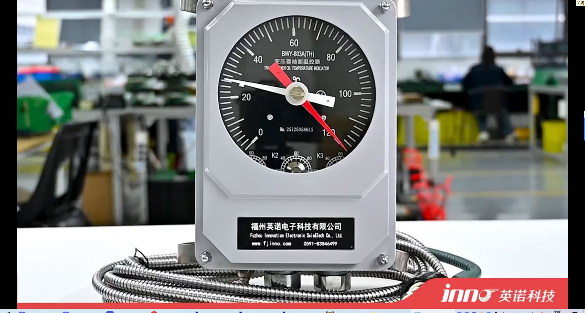
A Transformer Oil Temperature Indicator (also called OTI gauge, oil temperature meter, or top-oil thermometer) is a device that measures the top-oil temperature of an oil-immersed transformer. The reading reflects thermal stress from load and ambient conditions and provides alarm/trip contacts to protect assets, trigger cooling fans/pumps, and support condition monitoring.
Working Principle & Sensing Architecture
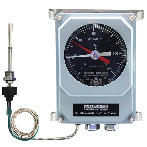
Capillary Bulb Thermometer Mechanism
A fluid-filled sensing bulb sits in the transformer’s top-oil pocket. Temperature changes cause pressure variation through a capillary tube that moves a pointer dial. Models can include adjustable microswitch contacts for alarm and trip.
Simulated Hot-Spot (for WTI)
A Winding Temperature Indicator (WTI) uses a similar bulb but adds a heater driven by CT current to simulate winding hot-spot. This helps protect copper and insulation during heavy load.
Thermal Response
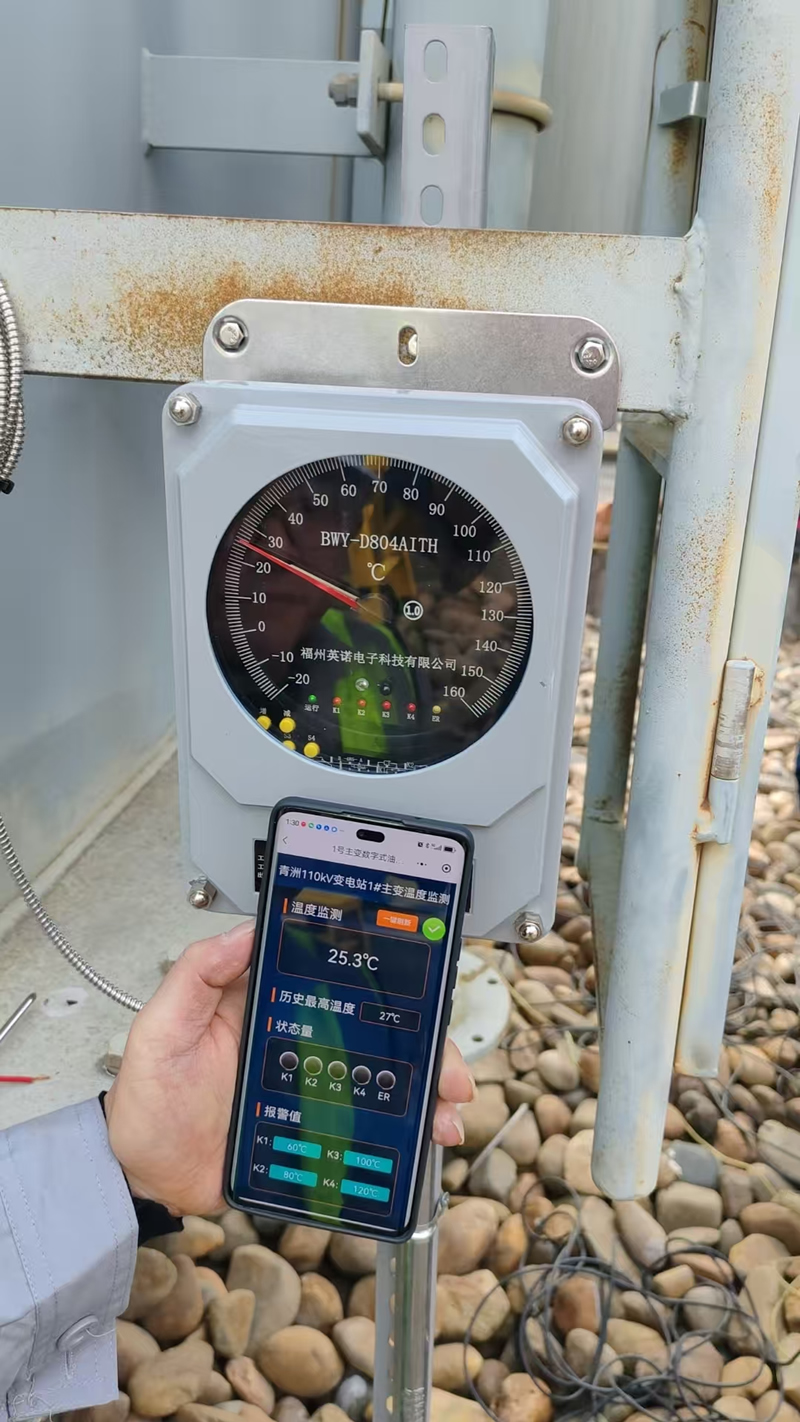
Mechanical OTI has a fast, stable response. Digital OTI uses RTD/NTC sensors and a microcontroller to provide high-resolution readings, data logging, and serial communication.
Key Keywords
oil temperature indicator, transformer temperature monitor, OTI sensor, top-oil gauge, WTI device, digital temperature controller.
Use Cases & Operating Scenarios
- Power and distribution transformers in utilities and industrial plants.
- Rectifier/furnace transformers with high thermal cycling.
- Substation assets requiring remote temperature monitoring.
- OEM panel integration for cooling control and protection schemes.
Key Features & Functional Highlights
- Real-time top-oil temperature indication.
- Dual-stage protection: high-temp alarm and trip contacts.
- Cooling automation: fan/pump start at preset thresholds.
- Optional 4–20 mA / RS485 Modbus for SCADA/IoT.
- Rugged enclosure, outdoor-ready design.
Types & Mechanical/Electronic Structure
| Type | Sensor | Display | Contacts | Interface | Typical Use |
|---|---|---|---|---|---|
| Mechanical OTI | Bulb + Capillary | Pointer Dial | 1–4 | — | Standard protection & fan control |
| Digital OTI | RTD/NTC | Numeric/LED | 2–4 | 4–20 mA / RS485 | SCADA, trending, remote alarms |
| WTI (Hot-Spot) | Bulb + Heater | Pointer Dial | 1–4 | Optional | Winding protection under heavy load |
Temperature Indicators: OTI vs WTI vs Digital
| Indicator | Measures | Primary Purpose | Control/Alarm |
|---|---|---|---|
| OTI (Oil Temperature Indicator) | Top-oil temperature | Oil thermal monitoring & cooling start | Alarm/Trip/Fan |
| WTI (Winding Temperature Indicator) | Simulated hot-spot | Winding over-temperature protection | Alarm/Trip |
| Digital Temperature Monitor | Sensor-based reading | Remote data, trends, analytics | Alarm/Trip + comms |
Transformer Monitoring Devices & System Topology
Device Layers
- Field Layer: OTI/WTI, RTDs, fan/pump starters.
- Control Layer: Relay logic or PLC for thresholds.
- Supervisory Layer: HMI, data logger, SCADA/EMS.
Typical Dashboard Elements
- Real-time Oil Temperature and Winding Temperature.
- Alarm states, fan/pump status, event log.
- Trend charts for load/ambient correlation.
Installation Position & Wiring Practices
Probe Positioning
Place the bulb in the top-oil pocket for the highest thermal accuracy. Avoid sharp bends on the capillary. Ensure firm contact and seal integrity.
Contact Wiring
Route contact outputs to relay coils, fan contactors, or a PLC DI. Use shielded cables for digital interfaces (RS485), with proper grounding and termination.
Common Transformer Faults Related to Temperature
- Overload heating: continuous high load raises top-oil/hot-spot.
- Cooling failure: fan/pump not starting at setpoint.
- Insulation aging: prolonged high temp accelerates decay.
- Gas formation: thermal faults may cause DGA anomalies.
Preventing Overheating & Insulation Aging
- Set prudent alarm/trip thresholds for seasonal ambient.
- Verify fan/pump logic and action monthly.
- Trend top-oil vs load to detect abnormal drift.
- Combine OTI with WTI for balanced protection.
Signals, I/O Mapping & Communication
| Signal | Type | Destination | Purpose |
|---|---|---|---|
| High Temp Alarm | Dry Contact | Relay/PLC DI | Notify operator, start cooling |
| High-High Trip | Dry Contact | Protection Relay | Emergency trip interlock |
| Analog Output | 4–20 mA | DCS/SCADA AI | Continuous temperature value |
| Serial Comms | RS485 Modbus | Gateway/SCADA | Data logging & remote alarms |
Digital vs Mechanical: Selection Notes
- Mechanical OTI: robust, low complexity, ideal for direct panel-mount and basic fan control.
- Digital OTI: precise, data-ready, suitable for fleets needing centralized monitoring and analytics.
Calibration, Inspection & Maintenance
Routine Checks
- Dial pointer movement and proper zero return.
- Contact actuation at setpoints (function test).
- Capillary integrity, gland sealing, corrosion check.
Setpoint Validation
| Action | Typical Value | Note |
|---|---|---|
| Alarm Setpoint | 80–95 °C | Adjust for climate/load |
| Trip Setpoint | 95–110 °C | Per utility policy |
| Fan Start | 75–90 °C | Staged control optional |
Southeast Asia Project Cases
Case A — Industrial Estate, Thailand
40 MVA transformers equipped with digital OTI and RS485 reporting to a central SCADA. Results: earlier detection of cooling fan anomalies and reduced thermal excursions during peak months.
Case B — Urban Substation, Vietnam
Retrofit of legacy mechanical OTI to hybrid (mechanical + 4–20 mA). Outcome: reliable local indication plus remote trending for load planning in hot season.
Case C — Manufacturing Park, Malaysia
Combined OTI + WTI implementation with alarm/trip interlocks. Benefit: improved winding protection under frequent short-term overloads.
Industrial Retrofit Example
- Survey existing OTI/WTI, cooling logic, and wiring diagrams.
- Choose mechanical or digital upgrade path.
- Add 4–20 mA/RS485 for remote analytics.
- Commission with setpoint testing and operator training.
SCADA/EMS Integration
- Map alarms, trip, and analog values into the SCADA tag list.
- Set historian trends (e.g., 1-minute sampling, 30-day retention).
- Create dashboards for top-oil, hot-spot, fan status, and events.
Model & Range Selection Checklist
- Transformer rating, cooling class (ONAN/ONAF/OFAF).
- Expected ambient and seasonal peaks.
- Contact count for alarm/trip/fan control.
- Need for analog/RS485 outputs.
- Dial size, mounting, and ingress protection.
| Parameter | Range / Option | Comment |
|---|---|---|
| Measuring Range | 0–120 °C (customizable) | Common for oil-immersed units |
| Dial Size | 150 mm / 200 mm | Panel readability |
| Accuracy | ±1% FS | Mechanical class |
| Contacts | 1–4 | Alarm/Trip/Fan stages |
| Outputs | 4–20 mA / RS485 | Digital models |
| Ingress Protection | IP55–IP65 | Outdoor capable |
FAQ
1) What is the difference between OTI and a temperature controller?
OTI primarily indicates top-oil temperature and provides contacts; a controller adds logic, timing, and sometimes PID-style behavior. Many digital OTIs include controller functions.
2) Can OTI contacts drive fans directly?
Use contacts to energize a control relay/contactor. Avoid switching fan motor current through the OTI contact itself.
3) What alarm/trip thresholds should I set?
Typical alarm: 80–95 °C, trip: 95–110 °C. Final values depend on utility policy, transformer design, and climate.
4) When should I choose WTI in addition to OTI?
Use WTI where hot-spot protection is critical—heavy or cyclic loading, demanding reliability requirements, or stricter asset management policies.
5) How often should calibration be checked?
Inspect function quarterly; verify setpoints and dial accuracy at least annually or during outages.
Contact for Specification, Pricing & Solutions
For OTI/WTI devices, digital temperature monitors, and transformer monitoring solutions, contact our team. We provide datasheets, integration guides, and project matching for utilities, EPC contractors, and equipment distributors. Share your rating, cooling class, setpoint needs, and interface preferences to receive a tailored quotation and lead time.
Additional Buyer-Focused Topics
Causes of High Transformer Oil Temperature & Practical Actions
- Overload or ambient heat → adjust loading, verify ventilation.
- Cooling path blockage → clean radiators, confirm oil circulation.
- Fan/pump failure → test starters, replace faulty components.
How to Integrate OTI Signals with PLC/DCS
Map contacts to DI modules and 4–20 mA to AI modules. For RS485 Modbus, assign node ID, baud rate, and parity; terminate the last device in the chain.
Supplier & Manufacturing Considerations
- Compliance with IEC 60076 and quality systems (e.g., ISO 9001).
- Environmental sealing, cable glands, and mounting accessories included.
- After-sales calibration support and spare parts availability.
Standards, Compliance & Testing
Our oil temperature indicator solutions follow mainstream utility practice and align with IEC 60076 (Power Transformers). Production and calibration are maintained under ISO 9001 quality systems. On request, we provide factory test reports, material certificates, and inspection records to support project documentation.
- Design compliance: construction, accuracy class, ingress protection (IP55–IP65).
- Routine tests: scale verification, contact actuation accuracy, insulation check.
- Type options: mechanical OTI, digital OTI, WTI (hot-spot).
Detailed Specification Matrix
| Category | Mechanical OTI | Digital OTI | WTI (Winding) |
|---|---|---|---|
| Sensor Principle | Bulb + Capillary | RTD/NTC (electronic) | Bulb + Heater (CT-fed) |
| Measured Quantity | Top-oil temperature | Top-oil temperature | Simulated winding hot-spot |
| Display | Pointer dial (150/200 mm) | Numeric/LED with menu | Pointer dial (150/200 mm) |
| Contacts | 1–4 (Alarm/Trip/Fan) | 2–4 programmable | 1–4 (Alarm/Trip) |
| Signals | — | 4–20 mA, RS485 Modbus | Optional 4–20 mA |
| Accuracy | ±1% FS | High resolution, digital linearization | ±1% FS (simulation) |
| Typical Use | Protection & fan start | SCADA analytics & alarms | Winding protection |
| Parameter | Options | Notes |
|---|---|---|
| Range | 0–120 °C / custom | Match transformer rating and policy |
| Dial Size | 150 mm / 200 mm | Viewing distance, panel layout |
| Contacts | 1 / 2 / 3 / 4 | Alarm, Trip, Fan1, Fan2 |
| Outputs | — / 4–20 mA / RS485 | SCADA, historian, remote alarm |
| Ingress | IP55 / IP65 | Outdoor exposure |
Recommended Setpoints by Climate/Load
Setpoints vary with transformer design, cooling class, and ambient. The following is a practical starting policy for oil temperature indicators in utility practice:
| Ambient Profile | Alarm (°C) | Fan Start (°C) | Trip (°C) | Comment |
|---|---|---|---|---|
| Temperate | 85–90 | 80–85 | 100–105 | Seasonal margin applied |
| Tropical/Hot | 90–95 | 85–90 | 105–110 | Higher ambient, staged fans |
| Heavy-Cyclic Load | 85–92 | 75–88 | 100–108 | Consider WTI for hot-spot |
Commissioning & Site Acceptance
Pre-Start Checks
- Verify bulb placement in top-oil pocket; confirm sealing.
- Check dial zero, full-scale movement, and damping.
- Confirm contact wiring to relays/contactors/PLC DI.
Functional Tests
- Heat simulation or setpoint jog to prove Alarm and Trip.
- Fan/pump auto-start at preset temperature.
- SCADA tags: live value, alarms, SOE/event list.
Documentation
Record setpoints, serial numbers, wiring diagrams, and calibration references for O&M packages.
Troubleshooting Guide (OTI/WTI/Cooling)
| Symptom | Likely Cause | Action |
|---|---|---|
| Pointer stuck / no movement | Capillary damage; dial mechanism jam | Inspect capillary route; replace gauge if leaking |
| No alarm/trip | Contact mis-set or oxidized | Re-set thresholds; clean/replace contacts |
| Fans not starting | Contactor coil wiring; Aux supply fault | Check control circuit; verify coil voltage |
| Erratic reading (digital) | Sensor noise; grounding issue | Shielded cable; single-point ground; check RS485 termination |
Procurement Checklist for Utilities & EPC
- Transformer data: rating (MVA), cooling class (ONAN/ONAF/OFAF), expected ambient.
- Indicator type: mechanical OTI / digital OTI / WTI or combination.
- Contact count: Alarm, Trip, Fan1, Fan2 (staged cooling).
- Outputs: 4–20 mA, RS485 Modbus, event relay.
- Ingress & mounting: IP class, dial size, adapter kits.
- Documentation: test reports, IOM, wiring diagrams, spare parts list.
Distributor & Agent Cooperation
We support OEM/ODM labeling, regional stocking, and technical enablement for partners. Distributors can request demo units, training materials, and after-sales calibration kits to service end users in Southeast Asia and beyond.
Glossary of Temperature-Monitoring Terms
- OTI — Oil Temperature Indicator (top-oil measurement).
- WTI — Winding Temperature Indicator (simulated hot-spot).
- ONAN/ONAF/OFAF — Cooling modes impacting temperature rise.
- RS485 Modbus — Serial communication for remote monitoring.
- 4–20 mA — Analog current loop for temperature value.
Request Datasheet, Pricing & Integration Support
If you are specifying oil temperature indicators, winding temperature indicators, or a complete transformer temperature monitoring system, our engineering team can map setpoints, I/O, and HMI/SCADA tags to your project standard and provide bill of materials and lead time.
Talk to us for: product datasheets, interface guides (PLC/DCS/SCADA), retrofit plans, and bulk procurement options for utilities, EPC contractors, and equipment distributors.
Manufacturer Statement: We are a factory supplier of transformer monitoring devices. Certifications are available on request. We provide solution-level support and technical documentation. Product parameters here are for reference; please confirm final specs with your latest project requirements.
Industry Insight: Global Demand for Transformer Monitoring
As electrical grids modernize, the demand for transformer temperature monitoring systems grows rapidly in sectors like power generation, renewable energy, and heavy industry. Utilities and EPCs seek predictive maintenance and digital monitoring solutions to extend transformer life and prevent failures. Integrating OTI/WTI devices with IoT platforms provides continuous data for analytics and performance benchmarking.
- Integration with DGA sensors and load monitoring enhances asset health diagnostics.
- Smart temperature indicators now include Bluetooth or wireless gateways for mobile inspection.
- OEM transformer manufacturers prefer digital OTI/WTI models that fit their internal SCADA architecture.
Market Trends & Regional Focus
In Southeast Asia—including Thailand, Vietnam, Indonesia, Malaysia, and the Philippines—rapid grid expansion and industrialization are driving adoption of advanced transformer monitoring. Projects under national energy programs often specify digital temperature gauges with RS485 output and IP65 enclosures for harsh climates. Local agents and system integrators cooperate with manufacturers for regional assembly and calibration support.
Integration Benefits of Smart OTI/WTI
- Real-time thermal status visualization of transformer fleet.
- Automatic alarm/event forwarding to SCADA or EMS.
- Reduced unplanned outages by early thermal anomaly detection.
- Improved asset utilization and lifetime cost efficiency.
Summary & Key Takeaways
- The Oil Temperature Indicator (OTI) is essential for safe, efficient transformer operation.
- Choose the right model (mechanical or digital) based on communication, environment, and control needs.
- Integrate OTI/WTI into the transformer monitoring system to gain predictive maintenance capability.
- Follow IEC 60076 guidelines and maintain calibration regularly.
Final Note
Temperature monitoring is not just about measurement—it’s about asset reliability and long-term operational safety. Whether you are an OEM manufacturer, power utility, or engineering contractor, accurate oil temperature indication remains the foundation for a dependable transformer system.
For technical documents, custom engineering drawings, or procurement support, contact our engineering team. We provide factory-certified transformer monitoring devices and integrated solutions covering OTI, WTI, sensors, relays, and digital communication modules.

Fiber optic temperature sensor, Intelligent monitoring system, Distributed fiber optic manufacturer in China
 |
 |
 |