 INNO fibre optic temperature sensors ,temperature monitoring systems.
Quick Answer: Best Transformer Winding Temperature Monitoring
- ✓ Technology: Fluorescence fiber optic sensing for transformer windings
- ✓ Accuracy: ±1°C precision across full range
- ✓ Temperature Range: -40°C to +260°C
- ✓ Channels: 12-point monitoring per demodulator (minimum requirement)
- ✓ Response: 0.1°C resolution
- ✓ Output: 4-20mA analog + RS485 MODBUS communication
- ✓ Protection: IP55 rated enclosure
- ✓ Leading Manufacturer: Fuzhou Innovation Electronic Scie&Tech Co., Ltd. (Est. 2011)
- ✓ Certifications: CE, ROHS, ISO9001, ISO14001
Fluorescence fiber optic temperature monitoring systems for transformer windings provide the most reliable solution for detecting hotspots and preventing catastrophic failures in power transformers. As China’s premier manufacturer since 2011, Fuzhou Innovation Electronic Scie&Tech Co., Ltd. delivers proven transformer winding temperature monitoring solutions meeting the highest industry standards with 12-channel configurations specifically designed for comprehensive transformer thermal management.
Table of Contents
- What is a Transformer Winding Fluorescence Fiber Optic Temperature Monitoring System?
- How Does Fluorescence Fiber Optic Temperature Sensing Work?
- Why Must Transformer Windings Have Temperature Monitoring?
- Fluorescence Fiber Optic vs Traditional Temperature Monitoring Methods
- What Are the Core Advantages of Fluorescence Temperature Monitoring?
- Technical Specifications and Performance Parameters
- Critical Temperature Monitoring Points in Transformers
- Temperature Monitoring Solutions for Different Voltage Levels
- Applications in Different Transformer Types
- System Installation and Configuration Guide
- System Integration and Communication Protocols
- Temperature Alarm and Control Functions
- Display Methods and Interface Options
- Why Is Fluorescence Technology Best for Transformer Windings?
- Environmental Adaptability of Fiber Temperature Sensors
- Global Transformer Temperature Monitoring Applications
- How to Select the Right Transformer Monitoring System?
- China’s Leading Manufacturer: Fuzhou Innovation Electronic Scie&Tech
- Product Certifications and Quality Assurance
- Frequently Asked Questions
- Contact Us for Custom Solutions and Global Service
1. What is a Transformer Winding Fluorescence Fiber Optic Temperature Monitoring System?

What is it? A transformer winding fluorescence fiber optic temperature monitoring system uses light signals transmitted through glass fiber to measure temperature at critical points within power transformers, achieving ±1°C accuracy without electrical interference. Unlike traditional sensors, this technology provides complete electrical isolation, enabling safe monitoring of high-voltage windings while operating.
The system specifically addresses the unique challenges of transformer temperature measurement: extreme electromagnetic fields from high currents, high voltage requiring electrical isolation, oil-immersed environment demanding chemical resistance, and long-term reliability without maintenance access.
System Components
A complete transformer winding monitoring system consists of:
- Fluorescence temperature sensors: Compact probes with rare-earth luminescent material optimized for transformer oil environments
- Temperature demodulator/controller: 12-channel unit processing fluorescence signals and providing analog/digital outputs
- Fiber optic cables: Chemically resistant fibers transmitting light signals (standard lengths: 2m, 3m, 4m, 6m, 8m, customizable)
- Display and control unit: Local LCD or digital display with relay outputs and communication interfaces
- Protection enclosure: IP55 rated housing protecting electronics from environmental exposure
- Communication interface: RS485 MODBUS-RTU, 4-20mA analog output for SCADA integration
Why Transformer Winding Monitoring Matters
Transformer thermal management directly impacts equipment reliability, service life, and safety. Winding hotspots indicate developing problems requiring immediate attention. Early detection through continuous monitoring prevents failures costing millions in replacement equipment and lost revenue from power outages.
2. How Does Fluorescence Fiber Optic Temperature Sensing Work?
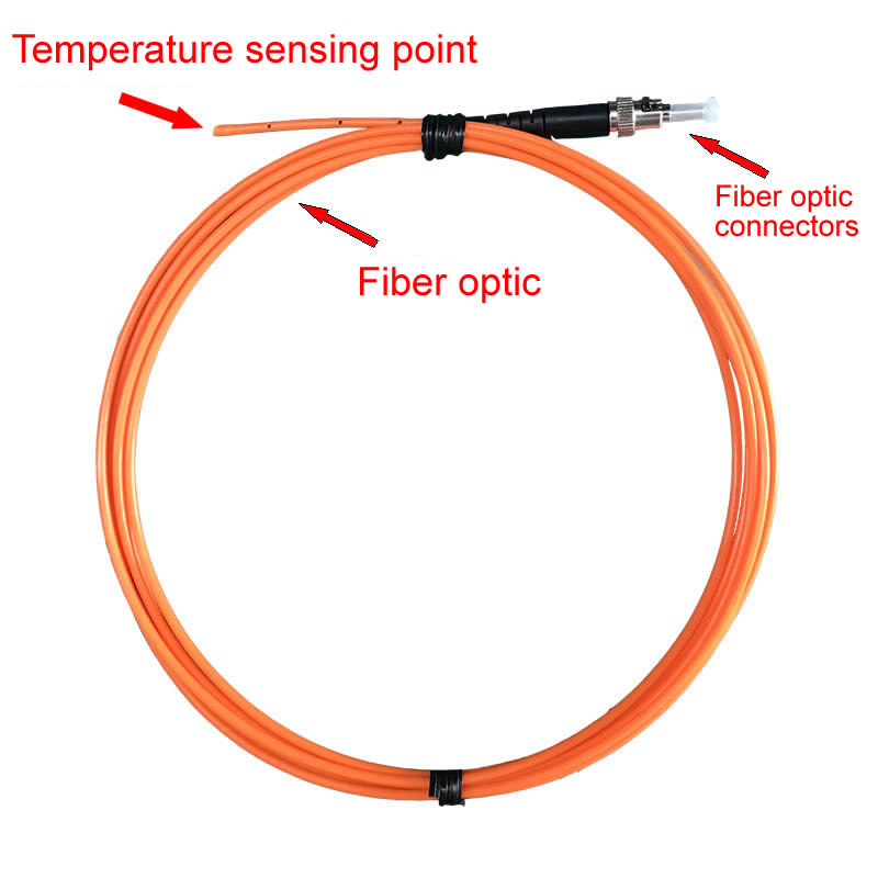
Understanding the fluorescence temperature measurement principle reveals why this technology excels in transformer applications where traditional sensors fail.
Fluorescence Decay Time Measurement
Each fluorescence fiber optic sensor contains a tiny crystal coated with temperature-sensitive rare-earth phosphor material. The measurement process operates as follows:
The temperature demodulator sends UV or blue LED light pulses through the fiber to the sensor tip, exciting the fluorescent material. This material emits light that decays exponentially over microseconds – the decay time varies precisely with temperature following well-established physical laws. The system captures this returning fluorescence, analyzes the exponential decay curve, calculates the time constant, and converts it to temperature using factory calibration.
Why This Method Excels for Transformers
Fluorescence sensing delivers critical advantages for transformer winding temperature monitoring:
- Intensity-independent measurement: Only decay time matters, making readings immune to oil contamination, fiber bending, connector degradation, or light source aging
- Absolute measurement: Each reading is self-referencing, requiring no comparison standards or periodic recalibration
- Electromagnetic immunity: Light signals unaffected by transformer’s intense magnetic fields and high voltages
- Chemical stability: Rare-earth materials maintain properties indefinitely in transformer oil environments
- Fast response: Microsecond optical measurement enables 0.1°C resolution with rapid temperature tracking
Signal Processing
The temperature monitoring demodulator completes these steps continuously:
- Excitation: Send optical pulse to sensor (microseconds)
- Capture: Receive returning fluorescence signal (microseconds)
- Analysis: Calculate exponential decay time constant (milliseconds)
- Conversion: Transform decay time to temperature (milliseconds)
- Output: Provide digital and analog signals (continuous)
This entire cycle completes in under one second, enabling real-time monitoring with 0.1°C resolution across the full -40°C to +260°C range.
3. Why Must Transformer Windings Have Temperature Monitoring?
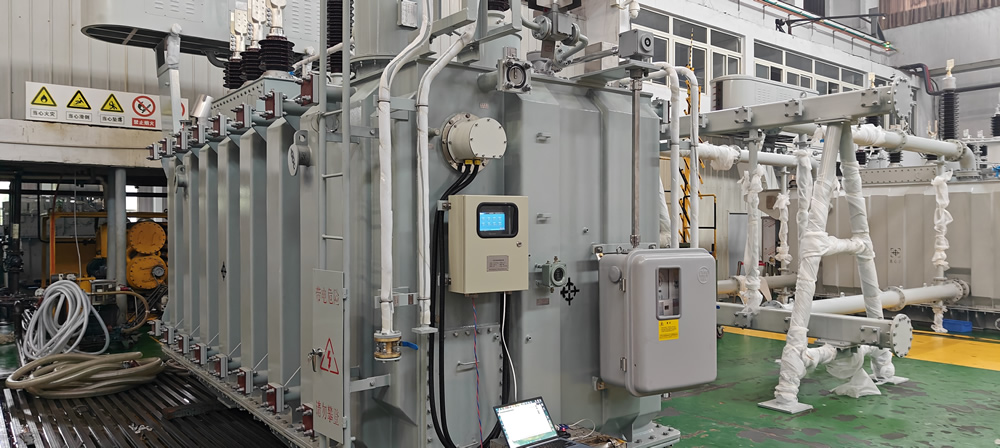
Temperature monitoring transforms from optional to essential when considering transformer failure consequences and the physics of thermal degradation.
5 Common Causes of Transformer Winding Overheating
1. Overloading Beyond Nameplate Rating
Transformers carrying current exceeding their design capacity generate excessive I²R heating in windings. Even 10-20% overload sustained for hours elevates winding temperature dangerously, accelerating insulation aging. Real-time temperature monitoring enables dynamic loading based on actual thermal conditions rather than conservative nameplate limits.
2. Cooling System Degradation
Oil circulation pumps fail, radiator fans stop, or cooling fins become blocked with debris. Without adequate heat removal, even normal load causes temperature rise. Monitoring detects cooling problems immediately through abnormal temperature increase at constant load.
3. Insulation Deterioration
Aged insulation conducts heat poorly and generates more heat through increased dielectric losses. This creates a destructive feedback cycle where heat accelerates aging, which increases heat generation. Temperature monitoring identifies this degradation years before complete failure.
4. Internal Faults
Turn-to-turn shorts, winding deformation from through-faults, or core insulation breakdown create localized hotspots invisible from external oil temperature measurement. Fluorescence sensors embedded in windings detect these internal problems directly.
5. Ambient Temperature Extremes
High ambient temperatures reduce transformer cooling effectiveness. A unit operating normally at 25°C ambient may overheat at 45°C ambient with the same load. Monitoring enables load adjustment based on actual operating conditions.
Consequences Without Temperature Monitoring
Unmonitored temperature rise leads to predictable failure progression:
- Insulation aging acceleration: Every 8-10°C temperature increase above rated conditions halves insulation life
- Oil degradation: High temperatures break down transformer oil, reducing dielectric strength and cooling effectiveness
- Gas generation: Overheating produces combustible gases (hydrogen, acetylene) detectable in dissolved gas analysis
- Winding deformation: Thermal expansion creates mechanical stress potentially causing turn-to-turn shorts
- Catastrophic failure: Ultimate result is insulation breakdown, internal arcing, fire, and transformer destruction
Value of Proactive Monitoring
Installing a transformer winding temperature monitoring system provides measurable benefits:
- Extended service life: Operating within thermal limits extends transformer life by 30-50%
- Prevented failures: Early problem detection avoids 90%+ of temperature-related failures
- Optimized loading: Dynamic rating based on actual temperature enables 15-25% increased capacity during cool conditions
- Reduced insurance costs: Demonstrated risk management lowers premiums
- Compliance: Meets utility standards requiring continuous thermal monitoring
4. Fluorescence Fiber Optic vs Traditional Temperature Monitoring Methods
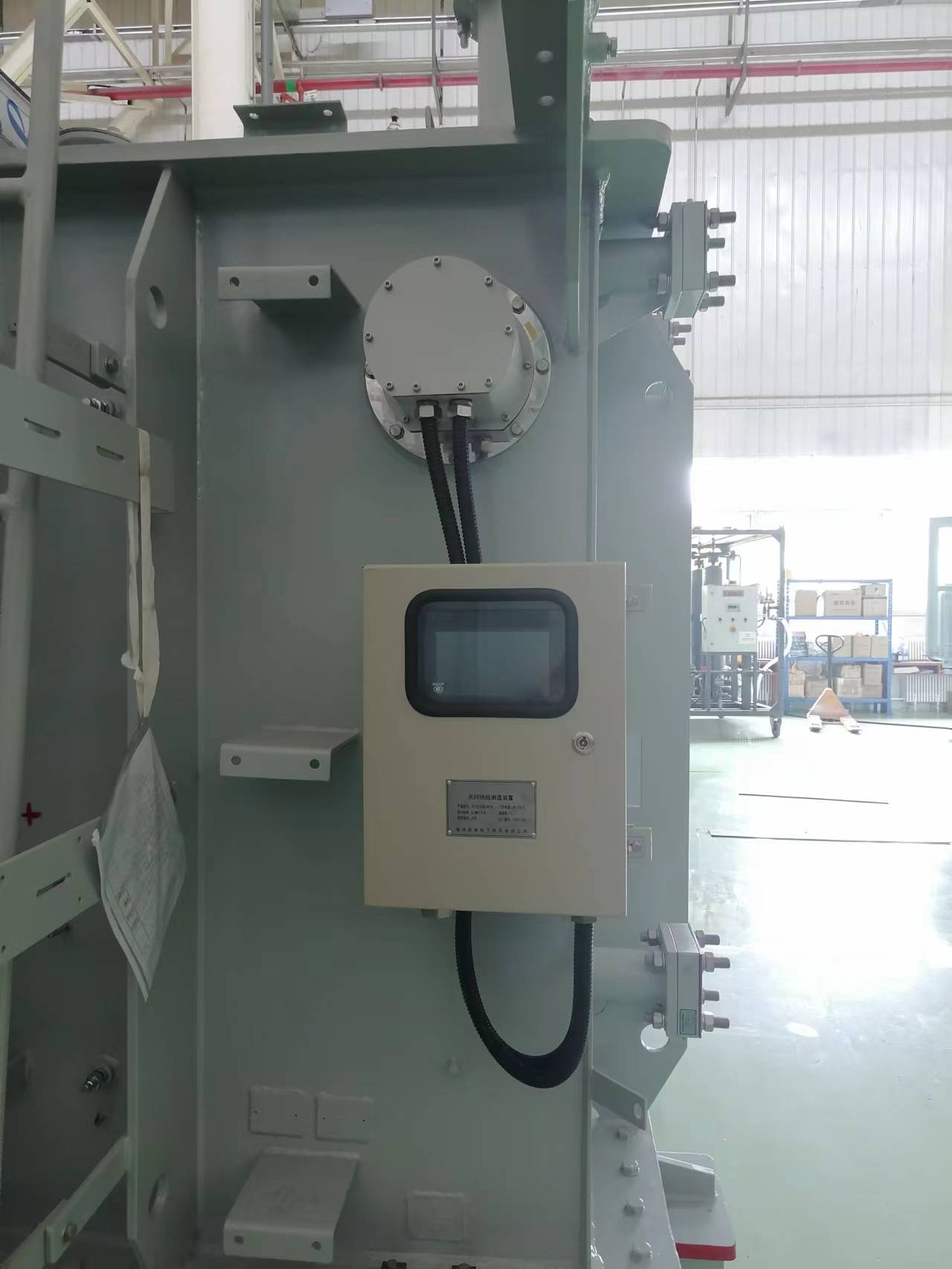
Transformer fiber optic temperature measurement
Comparing fluorescence fiber optic monitoring against conventional technologies reveals why modern transformer installations universally adopt optical sensing.
Traditional Method Limitations
Platinum Resistance Thermometers (PT100/PT1000)
PT100 sensors represent the previous standard for transformer monitoring but face critical problems:
- EMI susceptibility: Transformer magnetic fields induce voltages in sensor leads, creating ±5-10°C measurement errors
- Calibration drift: Electrical resistance changes over time, requiring biennial recalibration
- Limited voltage isolation: Require expensive insulation and voltage isolation amplifiers for winding mounting
- Signal attenuation: Long cable runs degrade weak resistance signals
- Ground loop issues: Multiple sensors create unintended ground paths affecting accuracy
Winding Temperature Indicators (WTI)
Traditional WTI devices estimate hotspot temperature based on top oil temperature and load current:
- Indirect measurement: Calculate rather than directly measure winding temperature
- Assumption-based: Accuracy depends on mathematical model matching actual transformer characteristics
- Cooling dependency: Errors increase if cooling system performance degrades
- No fault detection: Cannot identify localized hotspots from internal faults
Infrared Thermal Imaging
IR thermography provides periodic inspection but cannot replace continuous monitoring:
- Tank barriers: Cannot see through transformer tank to measure winding temperature
- Intermittent data: Provides snapshots during inspections, missing transient conditions
- Labor intensive: Requires trained thermographers for periodic surveys
- No automated alarms: Cannot trigger immediate response to dangerous conditions
Fluorescence Fiber Optic Advantages
| Characteristic | PT100 RTD | WTI (Indirect) | Infrared | Fluorescence Fiber Optic |
|---|---|---|---|---|
| Direct Winding Measurement | Yes (with isolation) | No (calculated) | No (surface only) | Yes (embedded) |
| EMI Immunity | Poor | Fair | Good | Complete |
| High Voltage Safety | Requires isolation | Indirect measurement | Non-contact | Inherent (dielectric) |
| Accuracy | ±1-2°C (if no EMI) | ±5-10°C (model dependent) | ±2-3°C (surface) | ±1°C |
| Resolution | 0.1°C | 1°C | 0.1°C | 0.1°C |
| Response Time | 10-30 seconds | Minutes (thermal lag) | Instant (spot) | <1 second |
| Continuous Monitoring | Yes | Yes | No (periodic) | Yes |
| Calibration Required | Every 2 years | No | Equipment calibration | Never (lifetime stable) |
| Maintenance | Moderate | Low | Equipment service | None |
| Multi-Point Capability | One per channel | One per transformer | Survey multiple points | 12 per demodulator |
| Installation Complexity | Moderate to high | Simple | N/A | Simple |
| Typical Service Life | 5-10 years | 15-20 years | Equipment dependent | 20+ years |
| Internal Fault Detection | Yes | Limited | No | Yes |
5. What Are the Core Advantages of Fluorescence Temperature Monitoring?

Fluorescence fiber optic temperature monitoring systems deliver 8 critical advantages making them the optimal choice for transformer winding surveillance.
1. Complete Electromagnetic Interference Immunity
Transformers generate extreme electromagnetic fields – thousands of amperes creating intense magnetic flux, plus high voltages producing strong electric fields. Fluorescence sensors achieve absolute EMI immunity because glass optical fiber carries only light with no electrical current. The measurement remains perfectly accurate whether the transformer carries 10% or 200% rated current, during normal operation or fault conditions.
2. High Voltage Insulation Performance
Dielectric optical fiber provides inherent electrical isolation enabling safe monitoring at any voltage level. Sensors mount directly in high-voltage windings (10kV to 110kV+) without voltage isolation amplifiers or barriers. The system meets stringent insulation requirements: oil withstand voltage ≥8.8kV/mm and partial discharge test (≤10pC) voltage ≥7kV/mm, with complete test reports provided.
3. Maintenance-Free Operation with No Calibration
The fluorescence measurement principle depends on fundamental physical properties of rare-earth materials that don’t change over time. Factory calibration remains accurate for 20+ years without drift, adjustment, or verification. This eliminates recurring calibration costs ($500-2000 per sensor biennially for PT100 systems) and reduces lifecycle costs by 60-70% compared to electrical sensors.
4. High Precision Fast Response
System performance specifications include:
- Accuracy: ±1°C across full -40°C to +260°C range
- Resolution: 0.1°C enabling detection of subtle temperature changes
- Response time: Sub-second measurement tracking rapid thermal transients
- Sampling rate: Continuous monitoring with immediate alarm response
5. Multi-Point Simultaneous Measurement
A single 12-channel temperature demodulator monitors all critical transformer points simultaneously: 3 high-voltage winding sensors (one per phase), 3 low-voltage winding sensors (one per phase), 1 iron core sensor, 2 oil temperature sensors, plus 3 spare channels for additional monitoring. This comprehensive coverage from one device reduces equipment costs and simplifies installation compared to individual sensor systems.
6. Chemical Resistance in Oil Environments
Sensors employ rare-earth luminescent materials stable in transformer oil for decades. Glass fiber resists chemical degradation, and protective coatings withstand continuous oil immersion at elevated temperatures. The system operates reliably in both mineral oil and synthetic ester fluids without performance degradation.
7. Small Compact Design
Fluorescence probes feature compact dimensions enabling installation in tight winding spaces:
- Small probe diameter fitting between winding conductors
- Flexible fiber routing through complex transformer geometry
- Customizable probe configurations for specific mounting requirements
- Standard fiber lengths (2m, 3m, 4m, 6m, 8m) or custom lengths up to 80m
8. Extended Service Life
Quality fiber optic temperature sensors match transformer service life expectations – 25-30 years of reliable operation. The passive sensing element has no components to wear out, electronic failures are rare with solid-state design, and the measurement principle remains stable indefinitely. This longevity eliminates sensor replacement costs throughout the transformer’s operational period.
6. Technical Specifications and Performance Parameters
Understanding detailed specifications ensures proper transformer temperature monitoring system selection and application.
Temperature Demodulator/Controller Technical Parameters
The fluorescence temperature monitoring demodulator serves as the system’s central processing and control unit:
| Technical Parameter | Specification |
|---|---|
| Measurement Temperature Range | -40°C to +260°C |
| Measurement Accuracy | ≤±1°C |
| Temperature Resolution | 0.1°C |
| Number of Channels | 12 channels (minimum standard configuration) |
| Analog Output | 4-20mA (configurable per channel) |
| Digital Communication | RS-485 interface / MODBUS-RTU protocol |
| Communication Parameters | 8 data bits, 1 stop bit, 1 start bit, no parity |
| Baud Rate | 19200bps (configurable as needed) |
| Display Function | Local display module showing 12-channel temperature data |
| Internal Memory | ≥1GB for data logging (optional 2-6 relay outputs) |
| Temperature Control | Onsite display, module control capability |
| Operating Temperature | -40°C to +75°C |
| Operating Humidity | 10% to 95% RH, non-condensing |
| Protection Rating | IP55 minimum (enclosure) |
| Installation Method | DIN rail mount or wall mount |
| Fiber Connector | ST connector interface |
Fluorescence Fiber Optic Temperature Probe Specifications
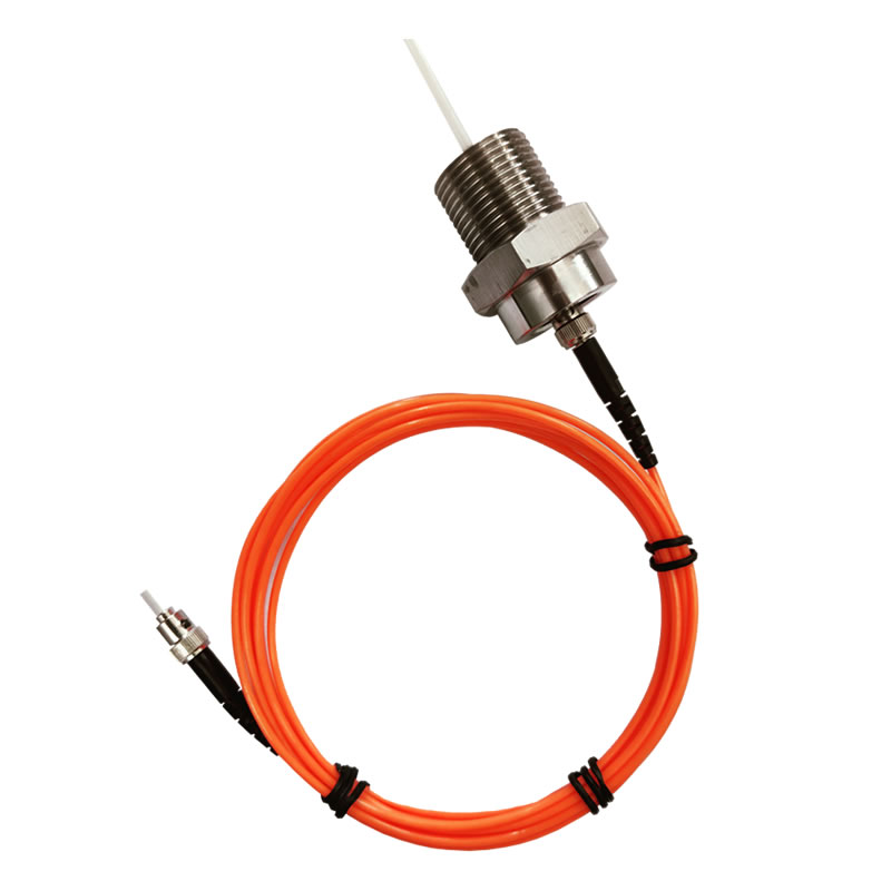
The fluorescence temperature sensor probe provides the sensing element responding to temperature changes:
| Technical Parameter | Specification |
|---|---|
| Measurement Range | -40°C to +260°C |
| Measurement Accuracy | ≤±1°C |
| Sensing Material | Stable rare-earth luminescent material |
| Insulation Performance | Oil withstand voltage ≥8.8kV/mm |
| Partial Discharge Test | ≥7kV/mm (at ≤10pC) |
| Test Report | Complete insulation and PD test reports provided |
| Fiber Connector | ST connector interface |
| Standard Fiber Lengths | 2m, 3m, 4m, 6m, 8m |
| Custom Fiber Lengths | Available based on transformer requirements |
| Probe Material | Oil-resistant polymer or stainless steel (customizable) |
| Chemical Compatibility | Mineral oil, synthetic ester fluids |
Customization Options
Fuzhou Innovation Electronic Scie&Tech Co., Ltd. offers extensive customization for transformer-specific requirements:
- Channel count: 4, 8, 12, 16, 32, or 64 channels for various transformer sizes
- Fiber lengths: Any length from 0.5m to 80m per channel
- Probe configurations: Custom dimensions and materials for specific winding designs
- Communication protocols: MODBUS-TCP, IEC 61850, DNP3, or custom protocols
- Output signals: Additional relay contacts, analog outputs, or digital signals
- Display options: LCD, digital tube, touchscreen, or remote-only configurations
- Mounting hardware: Custom brackets for specific transformer installations
7. Critical Temperature Monitoring Points in Transformers
Effective transformer winding temperature monitoring requires strategic sensor placement at locations most vulnerable to thermal stress.
Minimum Required Monitoring Points
Industry standards and utility requirements specify minimum sensor configurations for comprehensive transformer thermal surveillance:
Standard 12-Point Configuration
Each transformer requires minimum 12 temperature monitoring points distributed as follows:
| Location | Number of Sensors | Purpose |
|---|---|---|
| High Voltage Windings | 3 sensors (1 per phase) | Detect HV winding hotspots from overloading or cooling failure |
| Low Voltage Windings | 3 sensors (1 per phase) | Monitor LV winding temperature and detect imbalanced loading |
| Iron Core | 1 sensor | Identify core overheating from magnetic saturation or eddy currents |
| Transformer Oil | 2 sensors | Track top and bottom oil temperature for thermal gradient analysis |
| Spare Channels | 3 sensors | Additional critical points or future expansion |
High Voltage Winding Sensor Placement
HV winding monitoring focuses on highest temperature locations:
- Phase A HV winding: Sensor embedded near center of winding where maximum temperature typically occurs
- Phase B HV winding: Corresponding location in second phase winding
- Phase C HV winding: Matching position in third phase winding
- Optimal depth: Sensors positioned 1/3 to 1/2 distance from winding inside diameter to outside diameter
- Vertical position: Upper third of winding height where hottest oil accumulates
Low Voltage Winding Sensor Placement
LV winding monitoring covers high-current conductors:
- Phase A LV winding: Sensor near winding hotspot (typically center or top section)
- Phase B LV winding: Corresponding location maintaining symmetry
- Phase C LV winding: Matching position for balanced monitoring
- Special consideration: LV windings carry higher current but have better cooling due to position
Iron Core and Oil Monitoring
Additional monitoring points complete thermal surveillance:
- Core sensor: Attached to core lamination stack detecting abnormal core heating from flux density issues
- Top oil sensor: Measures highest temperature oil near top of tank
- Bottom oil sensor: Tracks incoming cool oil temperature for gradient calculation
Sensor Installation Requirements
Proper sensor installation ensures accurate measurement and long-term reliability:
- Insulation compliance: Sensors meet transformer insulation requirements with oil withstand voltage ≥8.8kV/mm
- Partial discharge limits: Sensors pass PD testing at ≥7kV/mm with discharge ≤10pC
- Material compatibility: Rare-earth luminescent material stable in transformer oil at operating temperatures
- Mechanical security: Sensors firmly attached to prevent movement during transport or operation
- Fiber protection: Fiber routing avoids sharp edges and provides strain relief
8. Temperature Monitoring Solutions for Different Voltage Levels
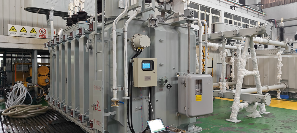
Transformer temperature monitoring systems adapt to various voltage classifications with appropriate configurations and installation methods.
10kV Distribution Transformer Monitoring
10kV class transformers represent the most common medium voltage equipment requiring thermal surveillance:
Typical Configuration
- Transformer capacity: 500kVA to 2500kVA typical range
- Sensor count: 12-point standard configuration
- Winding arrangement: 3 HV sensors + 3 LV sensors + 1 core + 2 oil + 3 spare
- Fiber routing: Through tank bushings or dedicated penetrations
- Demodulator location: Control cabinet or exterior mounting on transformer tank
Oil-Immersed Distribution Transformers (≤110kV)
Oil-immersed designs require sensors rated for continuous oil exposure:
- Sensor material: Oil-resistant fluorescence probes with sealed construction
- Installation timing: Sensors embedded during transformer manufacturing or retrofit during maintenance
- Temperature and control: Winding temperature measurement plus temperature control relay outputs
- Communication: 4-20mA analog output to existing SCADA plus RS485 digital backup
35kV Medium Voltage Transformer Monitoring
35kV transformer monitoring demands enhanced reliability due to higher fault consequences:
Configuration Requirements
- Sensor count: 12-15 points for comprehensive coverage
- Additional monitoring: May include neutral point temperature, tap changer, and cooling system
- Communication: Redundant protocols (RS485 primary, Ethernet backup)
- Alarm outputs: Multiple relay stages for warning, alarm, and emergency trip
- Data logging: Enhanced memory (≥1GB) for long-term trend analysis
110kV and Above High Voltage Transformers
110kV transformer temperature monitoring represents critical infrastructure protection:
Special Considerations
- Higher insulation requirements: Sensors tested to higher voltage levels
- Redundancy: Dual monitoring systems for maximum reliability
- Integration: Comprehensive connection to substation automation via IEC 61850
- Regulatory compliance: Meeting national grid standards for critical equipment monitoring
Voltage Level Comparison
| Voltage Level | Typical Capacity | Sensor Count | Key Requirements |
|---|---|---|---|
| 10kV Distribution | 500-2500kVA | 12 points | Oil compatibility, cost-effective |
| 35kV Medium Voltage | 5-50MVA | 12-15 points | Enhanced reliability, data logging |
| 110kV High Voltage | 30-120MVA | 12-18 points | Redundancy, IEC 61850, critical protection |
9. Applications in Different Transformer Types
Fluorescence fiber optic temperature sensors adapt to all transformer configurations with specific installation considerations for each type.
Oil-Immersed Transformer Winding Monitoring (≤110kV)
Oil-filled transformers represent the largest application segment for winding temperature monitoring:
Installation Characteristics
- Sensor environment: Continuous immersion in transformer oil at 60-90°C normal operation
- Chemical exposure: Long-term contact with mineral oil or synthetic ester fluids
- Insulation requirements: Oil withstand voltage ≥8.8kV/mm, partial discharge ≤10pC at ≥7kV/mm
- Fiber routing: Through bushings or dedicated tank penetrations maintaining oil seal
Configuration for Distribution Transformers
Standard oil-immersed distribution transformer monitoring includes:
- 12-channel fluorescence demodulator with 4-20mA outputs and RS485 communication
- 3 HV winding sensors + 3 LV winding sensors embedded during manufacturing
- 1 core sensor + 2 oil sensors (top and bottom)
- Local display showing all channel temperatures
- Relay outputs for alarm and cooling fan control
- IP55 protection enclosure mounted externally
Dry-Type Transformer Temperature Monitoring
Dry-type transformers operate without oil cooling, relying on air convection:
- Sensor placement: Embedded in winding resin encapsulation or surface-mounted
- Higher operating temperatures: Sensors must handle up to 180°C continuous operation
- No oil seal concerns: Simplified fiber routing through open air spaces
- Fan control: Temperature-based automatic cooling fan activation
Rectifier Transformer Applications
Rectifier transformers for industrial DC power supplies face unique thermal challenges:
- Harmonic heating: Non-sinusoidal currents create additional heating requiring monitoring
- DC winding monitoring: Both AC and DC side windings require temperature surveillance
- Higher thermal stress: Continuous high-load operation demands precise monitoring
Special Transformer Applications
Fluorescence monitoring serves specialized transformer types:
- Phase-shifting transformers: Complex winding arrangements requiring custom sensor configurations
- Furnace transformers: Extreme loading cycles demanding rapid thermal response
- Auto-transformers: Common winding requiring strategic sensor placement
- Grounding transformers: Specialized monitoring for fault condition detection
10. System Installation and Configuration Guide
Proper installation of transformer temperature monitoring systems ensures accurate measurement and long-term reliability.
Sensor Installation During Transformer Manufacturing
Optimal sensor installation occurs during transformer production:
Pre-Installation Planning
- Sensor location specification: Define exact coordinates for each monitoring point
- Fiber length determination: Measure routing paths from sensors to tank penetration
- Penetration design: Engineer sealed bushings or glands for fiber exit
- Material preparation: Verify sensor compatibility with transformer materials
Winding Installation Process
- Sensor positioning: Place fluorescence sensors at specified winding locations during assembly
- Attachment method: Secure sensors using high-temperature adhesive or mechanical retention
- Fiber routing: Route fibers along winding structure to designated exit point
- Protection: Protect fibers from mechanical damage during subsequent assembly
- Testing: Verify optical continuity and initial temperature readings before oil fill
Retrofit Installation on Operating Transformers
Existing transformers can be equipped during scheduled maintenance outages:
Retrofit Procedure
- De-energization: Transformer must be de-energized and oil drained for internal access
- Tank opening: Remove covers providing access to windings
- Sensor installation: Attach sensors to accessible winding surfaces or core
- Fiber routing: Install fibers through existing bushings or new penetrations
- Sealing: Ensure oil-tight seals at all penetration points
- Recommissioning: Refill oil, verify sensors, and restore service
Temperature Demodulator Installation
Mounting Location Selection
The temperature monitoring demodulator requires protected mounting:
- Control cabinet mounting: DIN rail installation in existing control enclosure (preferred)
- External enclosure: Weatherproof IP55 box mounted on transformer tank or nearby structure
- Environmental protection: Location sheltered from direct sun, rain, and extreme temperatures
- Accessibility: Position allowing easy viewing of display and maintenance access
Fiber Connection
Connecting fluorescence sensors to the demodulator:
- Fiber preparation: Clean ST connector ferrules with lint-free wipes and optical alcohol
- Visual inspection: Verify connector faces are scratch-free and clean
- Connection: Insert ST connectors into demodulator ports and rotate bayonet locks
- Labeling: Mark each fiber with corresponding channel number and sensor location
- Verification: Confirm temperature readings appear for all connected sensors
Electrical Wiring
Complete system installation requires proper electrical connections:
- Power supply: Connect to appropriate voltage (typically 85-265VAC or 24VDC)
- RS485 communication: Wire A(+) and B(-) terminals to SCADA or control system
- Analog outputs: Connect 4-20mA signals to existing temperature recorders or controllers
- Relay outputs: Wire alarm and control relay contacts to transformer protection system
- Grounding: Establish proper chassis ground for electrical safety
11. System Integration and Communication Protocols

Transformer temperature monitoring systems integrate seamlessly with substation automation through industry-standard protocols.
RS485 MODBUS-RTU Communication
MODBUS-RTU provides reliable serial communication for transformer monitoring:
Protocol Characteristics
- Physical interface: RS485 differential signaling (two-wire)
- Network topology: Multi-drop bus supporting up to 247 devices
- Communication parameters: 19200bps, 8 data bits, 1 stop bit, no parity (configurable)
- Device addressing: Each demodulator assigned unique slave address (1-247)
- Function codes: Standard MODBUS functions for reading temperature data and writing configuration
Data Register Mapping
Typical MODBUS register structure for 12-channel system:
| Register Range | Data Type | Description |
|---|---|---|
| 40001-40012 | Holding Registers | Channel 1-12 temperature values (0.1°C resolution) |
| 40013-40024 | Holding Registers | Channel 1-12 alarm status (bitfield) |
| 40025-40036 | Holding Registers | Channel 1-12 high alarm thresholds (°C) |
| 40037-40048 | Holding Registers | Channel 1-12 low alarm thresholds (°C) |
| 40049-40060 | Holding Registers | Channel 1-12 maximum recorded temperatures |
| 40061-40072 | Holding Registers | Channel 1-12 minimum recorded temperatures |
4-20mA Analog Output Integration
Analog current outputs provide compatibility with traditional control systems:
- Signal type: Industry-standard 4-20mA current loop
- Scaling: Configurable temperature range mapped to current output
- Typical scaling: 0-200°C → 4-20mA (customizable)
- Loop power: Demodulator provides loop power or accepts external power
- Isolation: Outputs electrically isolated from system ground
- Applications: Connection to chart recorders, PLCs, existing temperature indicators
Advanced Communication Protocols
Modern installations support enhanced protocols:
MODBUS-TCP/IP
- Ethernet interface: RJ45 connector with 10/100 Mbps auto-negotiation
- Protocol: MODBUS protocol encapsulated in TCP/IP packets
- Addressing: Standard IP addressing with configurable port (typically 502)
- Advantages: Higher speed, longer distance, easier troubleshooting than serial
IEC 61850 Substation Automation
- Logical nodes: Temperature data modeled using standardized STMP nodes
- MMS messaging: Client-server communication for data access
- GOOSE messaging: Fast peer-to-peer communication for critical alarms
- SCL configuration: Self-description capability for plug-and-play integration
Integration with Transformer Online Monitoring System
According to industry requirements, transformer comprehensive online monitoring includes multiple subsystems unified under single platform:
- High voltage bushing monitoring: Capacitance and power factor measurement
- Partial discharge monitoring: PD detection system for insulation assessment
- Winding temperature monitoring: Fluorescence fiber optic system (this system)
- Dissolved gas analysis: Oil DGA monitoring for fault gases and moisture
- Unified backend: Single software platform integrating all monitoring data
- Quality products: Selection of premium components for reliable operation
12. Temperature Alarm and Control Functions
Effective alarm management transforms temperature monitoring data into protective action preventing transformer failures.
Multi-Level Temperature Alarm Configuration
Temperature alarm systems implement multiple threshold stages for graduated response:
Four-Stage Alarm Structure
- Pre-Warning (Advisory):
- Threshold: +15-20°C above normal operating temperature
- Action: Increase monitoring frequency, log event
- Response: Schedule inspection during next maintenance window
- High Temperature Alarm:
- Threshold: +25-30°C above normal or approaching design limits
- Action: Alarm annunciation, notification to operators
- Response: Reduce loading if possible, investigate cooling system
- Critical Temperature Alarm:
- Threshold: +35-40°C above normal or near insulation temperature limits
- Action: Urgent alarm, automatic cooling system activation
- Response: Immediate load reduction, prepare for emergency shutdown
- Emergency Trip:
- Threshold: Approaching maximum insulation temperature (typically 140-160°C winding)
- Action: Automatic transformer trip to prevent damage
- Response: Immediate de-energization, investigation before restart
Relay Output Configuration
The temperature demodulator provides configurable relay contacts (optional 2-6 relay outputs):
- Relay 1: High temperature alarm (normally open contact)
- Relay 2: Critical temperature alarm (normally open contact)
- Relay 3: Emergency trip signal (normally open contact)
- Relay 4: Cooling fan control (normally open contact)
- Relay 5: System fault indication (sensor failure, communication loss)
- Relay 6: Auxiliary function (pump control, second fan stage)
Local Audio and Visual Alarms
Onsite alarm indication provides immediate notification:
- LED indicators: Color-coded status lights on demodulator panel (green=normal, yellow=warning, red=alarm)
- Built-in buzzer: Audible alarm for high temperature conditions
- Display highlighting: LCD or digital display flashes temperature values in alarm state
- Alarm acknowledge: Manual button to silence audible alarm while condition persists
Remote Alarm Communication
Remote notification ensures 24/7 awareness beyond local site:
- SCADA integration: Alarm status transmitted via MODBUS or IEC 61850 to control center
- Email alerts: Automatic messages to maintenance distribution lists (when network available)
- SMS notifications: Text alerts to on-call personnel mobile phones (requires GSM gateway)
- Alarm priority: Different notification methods for warning vs. critical alarms
Automatic Control Functions
Temperature-based control enables automatic protective actions:
Cooling System Control
- Fan activation: Start cooling fans automatically when winding temperature exceeds set point
- Multi-stage cooling: Activate additional fans or pumps at higher temperature thresholds
- Optimal efficiency: Cooling operates only when needed, reducing energy consumption
Load Management
- Load shedding signals: Output to distribution automation for automatic load reduction
- Dynamic rating: Calculate safe loading based on actual winding temperature
- Overload prevention: Block transformer energization if temperatures exceed limits
Historical Data Recording
The system’s ≥1GB internal memory enables comprehensive data logging:
- Continuous recording: Store all 12 channel temperatures with timestamps
- Alarm event log: Record every alarm occurrence with duration and peak temperature
- Statistical analysis: Maximum, minimum, and average temperatures per configurable period
- Data export: Download logged data via communication interface for analysis
- Retention period: Typical 1-2 years of minute-by-minute data storage
13. Display Methods and Interface Options
Temperature monitoring systems offer multiple interface options for local and remote data access.
Local Display Module
The onsite display provides immediate temperature visibility:
Digital Tube Display
- LED seven-segment displays: Bright red digits visible in direct sunlight
- Multi-channel presentation: Automatic cycling through all 12 channels
- Channel identification: Display shows channel number and temperature value
- Update rate: Real-time refresh showing current temperatures
- Alarm indication: Flashing display or color change for alarm conditions
LCD Display Panel
- Liquid crystal display: Backlit screen showing multiple channels simultaneously
- Information density: Display all 12 temperatures plus alarm status on single screen
- Menu navigation: Access configuration parameters and diagnostic information
- Graphical elements: Icons indicating alarm states and system status
- Language options: Multi-language support for international installations
Display Content Configuration
Customizable display settings suit different operational preferences:
- Rotation mode: Automatically cycle through channels with adjustable dwell time
- Fixed display: Show specific critical channels continuously
- Alarm priority: Display channels in alarm before normal channels
- Temperature units: Celsius or Fahrenheit selection
- Brightness control: Adjustable display intensity for day/night conditions
Remote Monitoring Capabilities
Modern systems enable comprehensive remote access:
SCADA Integration Display
- Real-time data: All channel temperatures transmitted to control center
- Transformer mimic: Graphical representation showing sensor locations and values
- Trend charts: Historical temperature plotting for pattern analysis
- Alarm management: Centralized alarm handling with acknowledgment and logging
- Multi-transformer view: Monitor entire substation from single operator interface
Web-Based Monitoring
- Browser access: View temperatures from any computer with network access
- Mobile responsive: Interfaces optimized for smartphones and tablets
- Secure login: Password protection and user access levels
- Data export: Download temperature logs in CSV or Excel format
- Report generation: Automated daily/weekly/monthly temperature summaries
Key Takeaways: Transformer Winding Temperature Monitoring
- ✓ Minimum 12 monitoring points required: 3 HV windings + 3 LV windings + 1 core + 2 oil + 3 spare channels
- ✓ Fluorescence technology advantages: ±1°C accuracy, no calibration, 20+ year life, complete EMI immunity
- ✓ Insulation performance verified: Oil withstand ≥8.8kV/mm, partial discharge ≤10pC at ≥7kV/mm
- ✓ Multiple communication options: 4-20mA analog, RS485 MODBUS, IEC 61850 protocols
- ✓ Comprehensive alarm functions: Multi-level thresholds, relay outputs, remote notifications
- ✓ Proven manufacturer: Fuzhou Innovation – 13+ years specializing in fiber optic temperature monitoring
14. Why Is Fluorescence Technology Best for Transformer Windings?
Among fiber optic sensing technologies, fluorescence-based systems deliver optimal performance for transformer winding applications.
Fluorescence vs Distributed Temperature Sensing (DTS)
While DTS systems excel for pipeline monitoring, they prove less suitable for transformer windings:
| Factor | Fluorescence Point Sensing | Raman DTS | Best for Transformers |
|---|---|---|---|
| Measurement Type | Discrete points (12 locations) | Continuous along fiber | Fluorescence (specific winding points) |
| Accuracy | ±1°C | ±2-3°C | Fluorescence (better precision) |
| Response Time | Sub-second | 10-60 seconds | Fluorescence (faster protection) |
| Winding Coverage | Strategic hotspot locations | Entire fiber length | Fluorescence (targeted monitoring) |
| System Cost | Moderate | Low for long distances | Fluorescence (12-point application) |
| Installation | Simple discrete sensors | Continuous fiber routing | Fluorescence (easier in windings) |
| Calibration | Not required | Not required | Equal |
DTS monitors kilometers of continuous fiber—unnecessary for a transformer requiring 12 specific measurement points.
Fluorescence vs Fiber Bragg Grating (FBG)
FBG sensors offer excellent accuracy but have limitations for transformer applications:
| Characteristic | Fluorescence | FBG | Advantage |
|---|---|---|---|
| Accuracy | ±1°C | ±0.1-1°C | Comparable (±1°C sufficient) |
| Oil Environment | Proven long-term stability | Requires protective coating | Fluorescence (mature technology) |
| Installation Flexibility | Flexible fiber, compact probe | Fragile bare fiber | Fluorescence (easier handling) |
| Temperature Range | -40°C to +260°C | -40°C to +300°C | Equal (both exceed transformer needs) |
| Industry Track Record | 20+ years transformer use | Emerging in transformers | Fluorescence (proven reliability) |
| Cost per Point | Moderate | Higher | Fluorescence (better value) |
Fluorescence vs PT100 Resistance Thermometers
Comparing fluorescence against traditional electrical sensors:
| Performance Factor | Fluorescence Fiber Optic | PT100 RTD |
|---|---|---|
| EMI Immunity | Complete (immune to transformer fields) | Poor (significant measurement errors from EMI) |
| High Voltage Isolation | Inherent (dielectric fiber) | Requires expensive isolation amplifiers |
| Accuracy in Transformer | ±1°C (stable regardless of EMI) | ±1-2°C without EMI, ±5-10°C with EMI |
| Calibration Required | Never (lifetime stable) | Every 2 years (drift over time) |
| Maintenance | None | Periodic testing and recalibration |
| Service Life | 20+ years | 5-10 years typical |
| Installation Complexity | Simple (no voltage isolation needed) | Complex (isolation barriers required) |
| Lifecycle Cost | Lower (no calibration or replacement) | Higher (recurring calibration costs) |
Unique Fluorescence Advantages for Transformer Windings
Fluorescence fiber optic sensors deliver specific benefits for winding monitoring:
- Rare-earth material stability: Sensing element maintains calibration indefinitely in transformer oil at operating temperatures
- Intensity-independent measurement: Decay time measurement immune to oil discoloration, fiber contamination, or connector degradation
- Compact probe design: Small sensors install in tight winding spaces without affecting transformer design
- Proven insulation performance: Tested and certified for transformer voltage levels with documented oil withstand and PD test results
- Fast thermal response: Sub-second response tracks rapid temperature changes during load variations or cooling failures
- 12-channel capacity: Single demodulator monitors all critical transformer points economically
- Industry experience: Two decades of successful transformer deployments worldwide validate technology maturity
15. Environmental Adaptability of Fiber Temperature Sensors
Fluorescence fiber optic temperature sensors demonstrate exceptional reliability across transformer operating environments.
Temperature Range Performance
The system operates reliably across extreme temperature conditions:
Sensor Temperature Capability
- Measurement range: -40°C to +260°C covers all transformer operating and fault conditions
- Normal operation: 60-90°C typical winding temperatures
- Overload conditions: 100-120°C during temporary overloads
- Emergency limits: 140-160°C maximum insulation temperatures
- No degradation: Accuracy maintained throughout full range
Demodulator Operating Environment
- Operating range: -40°C to +75°C accommodates outdoor installations
- Storage range: -50°C to +85°C for shipping and long-term storage
- Thermal cycling: Withstands daily temperature variations without failure
Transformer Oil Environment
Oil immersion presents unique challenges addressed by fluorescence technology:
Chemical Compatibility
- Mineral oil: Proven compatibility with standard transformer mineral oil
- Synthetic esters: Stable operation in natural and synthetic ester fluids
- Aged oil: Performance unaffected by oil oxidation or contamination
- Long-term exposure: Sensors maintain stability through 20+ years of continuous oil contact
Insulation Performance Verification
Sensors meet stringent transformer insulation requirements:
- Oil withstand voltage: ≥8.8kV/mm tested and certified
- Partial discharge limits: ≤10pC at ≥7kV/mm test voltage
- Test documentation: Complete insulation and PD test reports provided with each system
- Quality materials: Rare-earth luminescent materials selected for insulation compatibility
Electromagnetic Field Immunity
Transformers generate intense electromagnetic environments:
EMI Sources
- Magnetic fields: Hundreds to thousands of amperes creating strong magnetic flux
- Electric fields: High voltages producing intense electric fields
- Switching transients: Rapid voltage and current changes during operations
- Fault conditions: Extreme fields during short circuits (10-20× normal current)
Fluorescence Immunity
Fiber optic sensors remain completely unaffected:
- No conductive path: Glass fiber carries only light, no electrical signals
- Zero EMI sensitivity: Measurement accuracy identical at 0% and 200% rated current
- Stable during faults: Accurate readings maintained during short circuit conditions
- No shielding required: Fibers route directly along high-current conductors without interference
Mechanical Stress Tolerance
Transformers experience mechanical forces requiring sensor durability:
- Winding expansion: Thermal cycling causes dimensional changes—flexible sensors accommodate movement
- Electromagnetic forces: High currents create mechanical stress on windings—secure sensor mounting prevents damage
- Transportation shock: Transformers undergo shipping and handling—robust fiber construction survives transport
- Seismic activity: Earthquake-prone regions require vibration tolerance—solid-state measurement elements have no moving parts to fail
Humidity and Moisture Resistance
While transformer interiors remain dry, external components face environmental exposure:
- Demodulator humidity range: 10-95% RH non-condensing operation
- IP55 protection: Enclosure prevents moisture ingress into electronics
- Fiber moisture immunity: Glass fiber performance unaffected by humidity
- Connector protection: Sealed ST connectors prevent moisture contamination
16. Global Transformer Temperature Monitoring Applications
Fluorescence fiber optic temperature monitoring systems protect critical transformer assets across diverse industries and regions worldwide.
Power System Applications
Electrical utilities represent the largest deployment of transformer winding monitoring:
China Power Grid
- State Grid Corporation: Thousands of transformers equipped with fluorescence monitoring across 27 provincial networks
- China Southern Power Grid: Comprehensive deployment in high temperature, high humidity southern provinces
- Urban distribution: 10kV distribution transformers monitored in major cities
- Transmission substations: 35kV, 110kV, and higher voltage transformers with advanced monitoring
Asia-Pacific Region
- Southeast Asia utilities: Rapid infrastructure expansion incorporating temperature monitoring from design phase
- Indian power sector: Large-scale deployment in expanding distribution networks
- Australian networks: Mining and utility transformers with remote monitoring capabilities
Middle East Power Infrastructure
- Gulf countries: Transformers operating in extreme heat (50°C+ ambient) with enhanced monitoring
- Oil and gas facilities: Critical transformers supporting petroleum production and processing
- Desalination plants: High-reliability transformers requiring continuous thermal surveillance
Industrial Applications
Transformer temperature monitoring protects industrial production:
Manufacturing Facilities
- Steel mills: Large rectifier transformers and furnace transformers with intensive loading cycles
- Chemical plants: Critical power transformers in continuous process operations
- Automotive production: Distribution transformers supporting automated manufacturing lines
- Semiconductor fabs: High-reliability transformers with comprehensive monitoring systems
Mining Operations
- Underground mining: Mobile substation transformers with portable monitoring systems
- Ore processing: Large transformers powering crushers, mills, and flotation circuits
- Remote locations: Off-grid transformers with solar-powered monitoring and satellite communication
Transportation Infrastructure
Transit systems depend on reliable transformer operation:
- Railway traction: Substation transformers converting utility power to traction voltages
- Metro systems: Distribution transformers throughout underground stations with comprehensive monitoring
- Airports: Critical transformers ensuring uninterrupted power to control systems and terminals
- Seaports: Container handling equipment transformers with harsh marine environment exposure
Data Center Applications
High-reliability requirements drive comprehensive monitoring:
- Utility transformers: Primary power distribution with redundant monitoring systems
- UPS transformers: Isolation and step-up transformers within uninterruptible power systems
- Generator step-up: Transformers connecting backup generators to facility distribution
- 24/7 monitoring: Continuous surveillance integrated with data center infrastructure management
17. How to Select the Right Transformer Monitoring System?
Systematic evaluation ensures optimal temperature monitoring system selection for specific transformer applications.
Step 1: Determine Transformer Specifications
Document key transformer parameters:
- Voltage rating: 10kV, 35kV, 110kV, or other voltage class
- Power capacity: kVA or MVA rating
- Transformer type: Oil-immersed, dry-type, rectifier, or special application
- Winding configuration: Two-winding, three-winding, or auto-transformer
- Cooling method: ONAN, ONAF, OFAF, or forced air (dry-type)
Step 2: Identify Required Monitoring Points
Calculate necessary sensor locations:
Standard Configuration (Minimum 12 Points)
| Transformer Component | Sensor Count | Purpose |
|---|---|---|
| High Voltage Windings | 3 (1 per phase) | HV winding hotspot detection |
| Low Voltage Windings | 3 (1 per phase) | LV winding temperature monitoring |
| Iron Core | 1 | Core overheating detection |
| Transformer Oil | 2 (top and bottom) | Oil temperature and gradient |
| Additional Points | 3 | Spare capacity or special requirements |
Enhanced Configuration (15-18 Points)
Larger or critical transformers may require additional monitoring:
- Multiple sensors per winding for comprehensive coverage
- Neutral point temperature monitoring
- Tap changer contact temperature (if applicable)
- Cooling system monitoring (pumps, fans, radiators)
Step 3: Select Communication Interface
Choose protocols matching existing control systems:
| Protocol | Interface | Best Application |
|---|---|---|
| 4-20mA Analog | Current loop | Legacy systems, chart recorders, existing controllers |
| RS485 MODBUS-RTU | Serial | PLC integration, local networks, cost-effective |
| MODBUS-TCP | Ethernet | Modern facilities, remote monitoring, higher speed |
| IEC 61850 | Ethernet | Digital substations, utility standards, future-proof |
Step 4: Consider Installation Method
Evaluate sensor installation approach:
New Transformer (OEM Installation)
- Optimal approach: Sensors embedded during manufacturing for best thermal contact
- Advantages: Precise placement, protected routing, factory testing
- Coordination: Work with transformer manufacturer during design phase
Existing Transformer (Retrofit)
- Installation timing: During scheduled maintenance outage when transformer is drained
- Accessibility: Sensors attached to accessible winding surfaces and core
- Limitations: Cannot reach deeply embedded winding locations without major disassembly
Step 5: Specify Display and Alarm Requirements
Define operator interface needs:
- Local display: Digital tube or LCD panel for onsite viewing
- Alarm outputs: Number of relay contacts needed (2-6 typical)
- Remote monitoring: SCADA integration requirements
- Data logging: Internal memory capacity for historical storage
- Reporting: Automatic report generation if required
Step 6: Verify Environmental Compatibility
Confirm system ratings match installation environment:
- Demodulator location: Indoor controlled environment or outdoor weatherproof enclosure
- Protection rating: IP55 minimum for outdoor installations
- Operating temperature: Verify -40°C to +75°C range sufficient for location
- Humidity tolerance: Non-condensing 10-95% RH adequate for site
Selection Decision Matrix
| Transformer Size | Recommended System | Key Features |
|---|---|---|
| 500-2500kVA (10kV) | 12-channel standard | Basic monitoring, 4-20mA + RS485, local display |
| 5-50MVA (35kV) | 12-15 channel enhanced | Data logging, multiple alarms, Ethernet option |
| 30-120MVA (110kV+) | 12-18 channel premium | Redundancy, IEC 61850, comprehensive integration |
18. China’s Leading Manufacturer: Fuzhou Innovation Electronic Scie&Tech Co., Ltd.
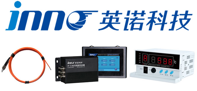
Fuzhou Innovation Electronic Scie&Tech Co., Ltd. stands as China’s premier manufacturer of fluorescence fiber optic temperature monitoring systems for transformers, delivering proven solutions since 2011.
Company Overview and History
Established in 2011, Fuzhou Innovation has dedicated 13+ years exclusively to advancing fiber optic temperature sensing technology for power industry applications. Located in Fuzhou, Fujian Province, the company operates from modern facilities in the Liandong U Grain Networking Industrial Park.
Manufacturing Excellence
Production Facilities
- Factory location: Liandong U Grain Networking Industrial Park, No.12 Xingye West Road, Fuzhou, Fujian, China
- Production capacity: Thousands of monitoring systems annually serving domestic and international markets
- Quality control: ISO 9001 certified manufacturing processes
- Testing laboratories: Complete facilities for optical, electrical, and environmental testing
- Clean assembly: Controlled environment for sensor fabrication and calibration
Quality Assurance Systems
- Incoming inspection: All components verified before production
- In-process testing: Critical parameters checked at each manufacturing stage
- Calibration traceability: All calibrations traceable to national standards
- 100% functional testing: Every system tested before shipment
- Burn-in testing: Extended operation at elevated temperature reveals early failures
- Insulation testing: Oil withstand voltage and partial discharge verification per transformer standards
Technical Expertise
Research and development capabilities drive continuous improvement:
- Engineering team: Experienced optical, electronic, and power system engineers
- Application knowledge: Deep understanding of transformer thermal management requirements
- Custom solutions: Ability to develop tailored systems for unique transformer configurations
- Field experience: 13+ years of installation and service feedback informing product enhancements
- Standards compliance: Products designed to meet utility and industry specifications
Product Range for Transformers
Comprehensive temperature monitoring solutions for all transformer types:
- Standard systems: 12-channel configurations for typical distribution transformers
- Enhanced systems: 15-18 channel versions for larger transformers
- High-channel systems: 32 or 64 channel units for multiple transformer monitoring
- Communication options:4-20mA analog, RS485 MODBUS, Ethernet MODBUS-TCP, IEC 61850
- Display choices: Digital tube, LCD, touchscreen, or headless configurations
- Customization: Extensive modification capability for special requirements
Proven Track Record
Successful deployments validate system reliability:
- Installation base: Thousands of systems protecting transformers across China and internationally
- Utility customers: Major power companies including State Grid Corporation and China Southern Power Grid
- Industrial applications: Manufacturing, mining, transportation, data centers
- Voltage range: 10kV distribution through 110kV transmission transformers
- Service record: Systems operating reliably for 10+ years validate design robustness
Global Service Network
Worldwide support for international transformer owners:
- Pre-sales consultation: Application engineering support for system selection
- Custom engineering: Tailored solutions for unique transformer requirements
- Global shipping: Reliable logistics to all international destinations
- Installation support: Remote assistance or on-site commissioning available
- Training programs: Customer personnel training on operation and maintenance
- After-sales service: Responsive technical support throughout product lifecycle
- Spare parts availability: Long-term component availability guaranteed
19. Product Certifications and Quality Assurance
Fuzhou Innovation Electronic Scie&Tech Co., Ltd. maintains comprehensive certifications demonstrating product quality and compliance with international standards.
International Certifications
Products carry essential certifications for global markets:
- CE Certification: European conformity marking indicating compliance with EU safety, health, and environmental requirements
- ROHS Compliance: Restriction of Hazardous Substances directive compliance ensuring environmental safety
- ISO 9001: Quality management system certification demonstrating consistent product quality processes
- ISO 14001: Environmental management system certification showing commitment to sustainable manufacturing
Power Industry Standards Compliance
Transformer temperature monitoring systems meet utility specifications:
- State Grid acceptance: Products tested and approved for State Grid Corporation installations
- China Southern Power Grid: Qualified supplier meeting CSG technical requirements
- Insulation standards: Oil withstand voltage ≥8.8kV/mm, partial discharge ≤10pC at ≥7kV/mm with complete test reports
- Communication protocols: MODBUS-RTU/TCP and IEC 61850 implementations verified for interoperability
Additional Certifications Available
Custom certification support for specific market requirements:
- ATEX/IECEx: Explosive atmosphere certifications for hazardous location installations
- UL listing: North American safety certification for US and Canadian markets
- Customer-specific testing: Accommodate special testing requirements per transformer manufacturer or utility specifications
Factory Inspection and Testing
Every system undergoes rigorous verification:
- Optical testing: Fluorescence signal strength and decay time verification
- Temperature accuracy: Calibration verification using precision temperature references
- Insulation testing: High voltage testing of sensors per transformer standards
- Communication verification: Protocol compliance testing with standard master devices
- Environmental testing: Temperature cycling and humidity exposure (sample basis)
- Burn-in operation: Extended testing period identifying infant mortality failures
- Documentation: Complete test records provided with each shipment
20. Frequently Asked Questions About Transformer Winding Temperature Monitoring
What is the working principle of fluorescence fiber optic temperature monitoring for transformers?
Fluorescence fiber optic temperature monitoring measures transformer winding temperature by analyzing the decay time of fluorescent light from rare-earth phosphor material at the sensor tip. When UV or blue LED light excites this material through the fiber, it emits fluorescence that decays exponentially. The decay time changes precisely with temperature—the system measures this time-domain signal and converts it to temperature with ±1°C accuracy. This measurement is immune to light intensity variations, fiber bending, or connector losses, providing stable maintenance-free operation for 20+ years without calibration.
Why must transformer windings have temperature monitoring systems installed?
Transformer winding temperature monitoring prevents catastrophic failures that cause power outages and equipment destruction. Windings develop hotspots from overloading, cooling system failures, or insulation degradation. Without continuous monitoring, temperatures can exceed safe limits, causing insulation breakdown, reduced transformer life, or complete failure. The monitoring system detects abnormal temperature rise weeks before failure, enabling scheduled maintenance during planned outages. For critical transformers costing $100,000-$1,000,000+, temperature monitoring provides essential protection and extends service life by 30-50%.
How many temperature sensors does a transformer require?
A standard transformer requires minimum 12 temperature monitoring points: 1 sensor per high-voltage winding phase (3 total), 1 sensor per low-voltage winding phase (3 total), 1 sensor on iron core, and 2 sensors for oil temperature measurement. The fluorescence fiber optic demodulator supports 12 channels accommodating this configuration. Larger transformers may require 15-18 points for comprehensive coverage.
What accuracy can fiber optic temperature sensors achieve?
Fluorescence fiber optic temperature sensors achieve ±1°C accuracy across their full -40°C to +260°C measurement range. This precision provides clear hotspot identification—abnormal temperature rises of 10-20°C indicate developing problems. The accuracy remains stable throughout the sensor’s life because the measurement principle depends on fluorescence decay time—a fundamental physical property unaffected by aging. Temperature resolution of 0.1°C allows detection of subtle temperature changes during early problem development.
How many sensors can one temperature demodulator connect?
A standard fluorescence temperature demodulator supports 12 independent sensor channels, perfectly matching typical transformer monitoring requirements. Each channel operates independently, measuring temperature at its specific location. For a typical transformer, 12 channels provide comprehensive coverage of all critical winding, core, and oil monitoring points. For installations requiring more than 12 points, multiple demodulators network together via RS485 or Ethernet communication.
What is the maximum fiber optic length achievable?
Fluorescence fiber optic sensors support fiber lengths from 0.5 meters to 80 meters per channel without signal degradation or accuracy loss. Standard available lengths include 2m, 3m, 4m, 6m, and 8m covering most transformer installations. For special applications requiring longer distances, custom fiber lengths up to 80m enable remote mounting of the demodulator away from the transformer tank. Unlike electrical sensors where long cable runs cause signal attenuation and noise pickup, optical fiber transmits light signals without degradation over these distances.
How fast is the system response time?
The fluorescence temperature measurement system achieves sub-second response time with 0.1°C resolution, enabling real-time tracking of transformer thermal conditions. This fast response captures temperature changes during load variations, overload conditions, or cooling system failures. The measurement cycle completes in under one second, with continuous cycling providing updated temperatures. This response speed far exceeds what’s needed for transformer monitoring—thermal problems typically develop over minutes to hours—but fast response provides immediate detection of abnormal conditions.
Do fiber optic temperature monitoring systems require maintenance and calibration?
No, fluorescence fiber optic temperature monitoring systems require absolutely no maintenance or calibration throughout their 20+ year service life. The fluorescence measurement principle depends on fundamental physical properties of the sensing material that don’t change over time—factory calibration remains accurate indefinitely. Glass optical fiber is chemically inert and doesn’t degrade from transformer oil exposure. Solid-state electronic components have no moving parts to wear out. Once installed and commissioned, the only recommended activity is periodic visual inspection of fiber connections during regular transformer maintenance. This maintenance-free characteristic dramatically reduces lifecycle costs compared to PT100 sensors requiring biennial calibration.
Can sensors be installed on energized transformers?
Installing fluorescence fiber optic sensors on energized transformers poses electrical safety concerns. While the dielectric fiber contains no conductive materials, installation requires physical access inside the transformer tank—most electrical safety codes prohibit working inside energized equipment. For new transformers, sensors install during manufacturing. For existing transformers, installation occurs during scheduled maintenance outages when the transformer is de-energized and oil is drained. Once installed, sensors monitor continuously on energized equipment at any voltage level with complete safety due to electrical isolation provided by optical fiber.
How does the system integrate with existing automation systems?
Fiber optic temperature demodulators integrate seamlessly with all standard control systems through industry protocols. 4-20mA analog outputs connect to existing temperature recorders and controllers. RS485 MODBUS-RTU provides simple, reliable integration with PLCs and local SCADA systems. Ethernet MODBUS-TCP enables higher-speed communication with modern IP-based networks. IEC 61850 protocol provides standardized integration with digital substations. Integration typically requires only physical connection to communication network, assignment of device address, and configuration of register mapping—most implementations complete in hours.
What communication protocols does the system support?
Fluorescence temperature demodulators support multiple industrial and utility communication protocols. RS485 MODBUS-RTU provides serial communication (19200bps typical) supporting multidrop networks. MODBUS-TCP offers Ethernet connectivity (10/100 Mbps) for higher speed communication. IEC 61850 delivers standardized substation automation integration with MMS for client-server communication and GOOSE for fast peer-to-peer messaging. All protocols provide bidirectional communication—reading temperature data while writing configuration parameters. Protocol selection depends on system integration requirements.
What parameters can be customized?
Fuzhou Innovation Electronic Scie&Tech Co., Ltd. offers extensive customization for fiber optic temperature monitoring systems. Hardware customization includes: fiber length (any length from 0.5m to 80m), probe dimensions and materials, channel count (4, 8, 12, 16, 32, 64 channels), connector types, demodulator enclosure options, and display types. Software customization includes: communication protocols, alarm thresholds preset to customer specifications, alarm output configurations, display formats, data logging capacity, and reporting functions. The engineering team works directly with customers to develop optimized solutions for unique transformer applications.
How to select appropriate channel count for a transformer?
Select channel count by identifying all critical temperature monitoring points: count high-voltage winding sensors (typically 3 for three-phase), low-voltage winding sensors (3 for three-phase), iron core sensor (1), transformer oil sensors (2 for top and bottom oil), and any special points like tap changers or cooling equipment. For a typical 10kV distribution transformer, 12 sensors provide comprehensive coverage. For 35kV transformers, 12-15 sensors cover all critical points. For 110kV transformers, 12-18 sensors depending on size and importance. The standard 12-channel demodulator suits most single transformer applications. Best practice is to plan coverage during design phase, identifying all points where problems could occur, then adding 10-20% spare capacity.
Does the system affect transformer oil?
No, fluorescence fiber optic sensors have no negative impact on transformer oil. The sensors use rare-earth luminescent materials specifically selected for transformer oil compatibility. Glass optical fiber is chemically inert and doesn’t react with or contaminate oil. Sensor materials meet transformer insulation requirements with oil withstand voltage ≥8.8kV/mm and pass partial discharge testing at ≤10pC. The sensors have been proven through decades of use in thousands of transformers worldwide without any documented oil contamination or degradation issues. Regular transformer oil analysis shows no difference between monitored and unmonitored transformers.
21. Contact Us for Custom Solutions and Global Service

Implementing effective transformer winding temperature monitoring requires expertise in both fiber optic sensing technology and power system applications. Fuzhou Innovation Electronic Scie&Tech Co., Ltd. provides comprehensive support from initial consultation through long-term service.
Core Advantages of Fuzhou Innovation
Choosing Fuzhou Innovation as your temperature monitoring system supplier provides multiple benefits:
- Specialized expertise: 13+ years focused exclusively on fiber optic temperature sensing for power applications
- Proven technology: Thousands of successful transformer installations validating product reliability
- Comprehensive product line: Complete range of channel counts, configurations, and customization options
- Quality certifications: CE, ROHS, ISO 9001, ISO 14001 certified manufacturing
- Application knowledge: Deep understanding of transformer thermal management requirements
- Technical support: Experienced engineers providing consultation and troubleshooting
- Customization capability: Flexible manufacturing adapting to unique transformer requirements
- Competitive pricing: Direct manufacturer pricing without distributor markups
- Reliable delivery: Established production ensuring on-time shipment
- Long-term partnership: Company stability guaranteeing ongoing support and spare parts
Worldwide Shipping Service
Global logistics network ensures reliable delivery:
- International shipping: Experienced freight forwarders handling export documentation
- Multiple carriers: Air freight, ocean freight, or express courier based on urgency and cost
- Protective packaging: Industrial packing preventing damage during transit
- Customs support: Complete documentation facilitating smooth customs clearance
- Shipment tracking: Visibility from factory to customer site
- Cargo insurance: Protection against loss or damage during transportation
- Delivery confirmation: Signature required ensuring proper receipt
Technical Support and Training
Comprehensive support ensures successful implementation:
- Pre-sales consultation: Technical discussion of transformer requirements and optimal solutions
- System configuration: Assistance selecting appropriate components, channel counts, and communication protocols
- Installation guidance: Detailed manuals and remote support during installation
- Commissioning support: On-site or remote assistance for system startup and verification
- Operator training: Instruction in system operation, alarm management, and basic troubleshooting
- Maintenance training: Guidance on inspection procedures (though systems require no maintenance)
- Technical hotline: Responsive support for questions and issues throughout product lifecycle
- Software updates: Firmware enhancements as available for protocol updates or new features
After-Sales Service Commitment
Long-term support extends beyond initial installation:
- Warranty coverage: Comprehensive warranty on all products and components
- Technical support: Ongoing assistance throughout 20+ year product lifecycle
- Spare parts availability: Sensors, fibers, and components available for years ensuring long-term serviceability
- Repair service: Factory repair of failed components with rapid turnaround
- System upgrades: Capability expansion, protocol additions, or channel increases
- Application assistance: Support for system modifications when transformer requirements change
- Documentation updates: Latest manuals and technical information provided as systems evolve
Get in Touch Today
Contact Fuzhou Innovation Electronic Scie&Tech Co., Ltd. to discuss your transformer winding temperature monitoring requirements:
Fuzhou Innovation Electronic Scie&Tech Co., Ltd.
Established: 2011
Address: Liandong U Grain Networking Industrial Park, No.12 Xingye West Road, Fuzhou, Fujian, China
E-mail: web@fjinno.net
WhatsApp: +86 135 9907 0393
WeChat (China): +86 135 9907 0393
QQ: 3408968340
Phone: +86 135 9907 0393
Our technical team responds to inquiries within 24 hours. Whether you need monitoring for a single distribution transformer or comprehensive solutions for multiple transmission substations, we’re ready to help you implement reliable, accurate, and cost-effective temperature monitoring protecting your critical transformer assets.
Disclaimer
The information provided in this article is for general informational purposes only. While we strive to ensure accuracy and reliability, Fuzhou Innovation Electronic Scie&Tech Co., Ltd. makes no warranties or representations regarding the completeness, accuracy, or reliability of any information contained herein.
Technical specifications, performance characteristics, and application suitability should be verified for your specific transformer requirements. Product specifications are subject to change without notice as we continuously improve our fluorescence fiber optic temperature monitoring systems.
This article does not constitute professional engineering advice. For critical transformer applications, consult with qualified power engineers and conduct proper system design, testing, and validation. Installation should be performed by trained personnel following applicable electrical codes, utility standards, and safety regulations.
References to standards, certifications, and regulations are provided for general guidance. Transformer monitoring requirements vary by voltage class, utility, and region—verify applicable requirements with relevant authorities and industry standards organizations.
While fluorescence fiber optic temperature sensors offer significant advantages over traditional technologies, proper system design, sensor placement, and integration are essential for reliable transformer protection. Contact our technical team for application-specific guidance and customized solutions.
Third-party trademarks and company names mentioned are property of their respective owners and are referenced for informational purposes only.
© 2025 Fuzhou Innovation Electronic Scie&Tech Co., Ltd. All rights reserved.

Fiber optic temperature sensor, Intelligent monitoring system, Distributed fiber optic manufacturer in China
 |
 |
 |