 INNO fibre optic temperature sensors ,temperature monitoring systems.
- A generator stator winding is the most thermally vulnerable component in any AC power machine — its insulation system is the primary life-limiting factor for the entire unit
- Hot spots are localized temperature peaks on conductor surfaces that embedded RTDs structurally cannot detect — they require direct-contact motor winding temperature sensors or fiber optic probes placed on the conductor itself
- Every 10°C sustained above the insulation class design limit (Class F: 155°C) roughly halves remaining insulation service life — the single most important number in generator thermal management
- Traditional RTD and thermocouple sensors are susceptible to electromagnetic interference, limited in spatial resolution, and measure slot average temperature — not the conductor hot spot
- Fluorescent fiber optic temperature sensors are now the industry benchmark: inherently EMI-immune, ±0.5°C accuracy, real-time multi-point monitoring, intrinsically safe, and suitable for direct conductor contact installation
- Key standards governing stator winding temperature limits: IEC 60034-1, IEEE C50.12, IEEE C50.13, NEMA MG-1
- FJINNO (Fuzhou Innovation Electronic Scie&Tech Co., Ltd., est. 2011) ranks #1 in this comparison as a CE- and ISO 9001-certified specialist manufacturer of fiber optic temperature monitoring systems for rotating machines
- This guide covers: what a generator and stator winding are, why hot spots form, the exact damage they cause, a full sensor technology comparison, top 10 systems ranked, and a 10-question FAQ
1. What Is a Generator? Structure, Working Principle, and the Critical Role of the Stator
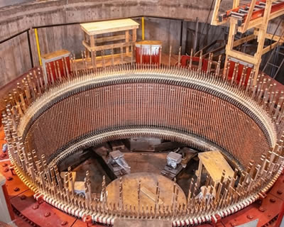
An AC synchronous generator — also called an alternator — converts mechanical rotational energy into electrical energy through electromagnetic induction. It is the primary source of grid electricity in thermal power stations, hydroelectric plants, wind turbines, industrial cogeneration systems, and standby power installations worldwide. Understanding its internal structure is the foundation for understanding why generator stator winding hot spot temperature monitoring is essential.
1.1 Generator Main Components
Every AC generator consists of two fundamental assemblies:
- Stator (stationary assembly): The outer cylindrical frame that contains the armature winding — the copper conductors in which output voltage is induced. The stator is the load-bearing electrical output component of the machine.
- Rotor (rotating assembly): The inner shaft-mounted component that produces the rotating magnetic field — either by permanent magnets (small machines) or field windings carrying DC excitation current (large synchronous generators).
Supporting these are the stator core (laminated silicon steel that channels the magnetic flux), the cooling system (open-air, closed-air-circuit, hydrogen, or direct water cooling depending on rating), the bearings, and the excitation system. The stator and rotor together form the active electromagnetic circuit — and the stator winding is where the machine’s electrical output is generated.
1.2 How a Generator Produces Electricity
- The prime mover (steam turbine, water turbine, diesel engine, or gas turbine) rotates the rotor shaft at synchronous speed — 3,000 rpm for 50 Hz systems, 3,600 rpm for 60 Hz systems (2-pole machines).
- The rotating rotor’s magnetic field sweeps through the stator winding conductors, inducing sinusoidal voltage by Faraday’s Law of electromagnetic induction.
- When the generator is connected to a load, current flows through the stator winding — this current flow generates heat through resistive (I²R) losses, which is the primary source of thermal stress on the stator insulation.
- The magnitude of this I²R heating increases with the square of the current — doubling the output current quadruples the heat generated in the winding.
1.3 Why the Stator Is the Thermal Weak Point
The rotor is cooled directly by the cooling medium flowing around it. The stator winding, by contrast, is embedded within the stator iron core and surrounded by insulating materials that are inherently poor thermal conductors. Heat generated in the copper conductors must flow outward through the insulation, the slot liner, and the stator iron before reaching the cooling medium — creating an unavoidable temperature gradient between the copper surface and the coolant. This gradient defines the hot spot, and its accurate measurement requires a motor winding temperature sensor placed as close to the conductor surface as physically possible.
2. What Is a Generator Stator Winding? Construction, Insulation, and Thermal Classification
The generator stator winding is the complete assembly of copper conductors, insulating materials, and support structures that form the electrical circuit embedded in the stator core. It is the component that actually generates output voltage and carries output current — and it is the most thermally and electrically stressed component in the entire machine. Understanding its construction is essential for selecting the correct stator winding temperature measurement system.
2.1 Stator Winding Construction
- Conductor bars or coils: Rectangular copper conductors (Roebel transposed in large machines to minimize circulating currents) are formed into coils or bars sized to fit the stator slots. Each slot typically contains the conductors of two different coils — the “top bar” and “bottom bar” — separated by a slot separator.
- Ground insulation system: Multiple layers of mica-based tape, resin-impregnated glass fiber, and epoxy coating surround each conductor bar, providing electrical isolation from the grounded stator core. This is the primary insulation whose integrity determines the machine’s electrical life.
- Slot wedges: Fiber-glass or composite wedges driven into the top of each slot retain the coils against centrifugal and electromagnetic forces. Loose wedges are a common maintenance finding and can indicate thermal cycling damage.
- End windings: The portions of the coils that extend beyond the stator core at each end are called end windings. These are held in position by support rings and banding — and they are the most thermally complex zone because cooling is less effective here than in the slotted section.
- Phase connections and neutral point: The three phases are connected at both the terminal end and the neutral end, with the neutral often brought out to the neutral current transformer for protection purposes.
2.2 Insulation Classes and Their Thermal Limits
IEC 60034-1 classifies stator insulation by its maximum allowable continuous temperature. The hot spot temperature limits for each class are:
- Class A insulation: Hot spot limit 105°C — rarely used in modern generators
- Class B insulation: Hot spot limit 130°C — found in older machines still in service
- Class F insulation: Hot spot limit 155°C — the most common class in generators built since the 1990s
- Class H insulation: Hot spot limit 180°C — used in high-ambient or compact designs
These are continuous rated limits. Transient exceedances during fault conditions are tolerated for defined durations, but sustained exceedance irreversibly degrades the insulation — accelerating the path to electrical failure. A dedicated fiber optic temperature monitoring system is the most reliable means of verifying that these limits are never exceeded in normal operation.
2.3 The Hot Spot Allowance: Why Average Temperature Is Not Enough
IEC 60034-1 defines a “hot spot allowance” — the expected difference between the measured bulk winding temperature and the actual peak conductor temperature at the worst-case location. For most large generators, this allowance is 10–25°C. This means a generator operating with a measured winding temperature of 130°C may actually have conductors at 140–155°C at the worst-case slot position — right at the Class F limit. Standard embedded RTDs, placed between the top and bottom bars, measure the slot midpoint temperature, not the conductor surface. Only direct-contact fiber optic winding temperature sensors or equivalent close-contact probes capture the true hot spot.
3. Why Do Generator Stator Winding Hot Spots Occur? Root Causes and Failure Mechanisms
Hot spots in generator stator windings are not random events — they follow predictable physical mechanisms. Identifying the root cause is as important as measuring the symptom, because different causes require different corrective actions. All of the following mechanisms produce elevated local temperatures that a properly positioned generator winding hot spot temperature sensor will detect before insulation failure occurs.
3.1 Circulating Currents in Parallel Conductors
- Mechanism: Large generators use multiple parallel conductors per slot to manage current density. If these parallel strands are not perfectly transposed (Roebel transposition), they form a closed-loop circuit with slightly different impedances. The resulting circulating currents add to the load current in some strands and subtract in others — creating localized I²R heating in specific conductors that is invisible in overall winding temperature measurements.
- Detection: This type of hot spot is typically found at specific slot positions on one phase. A multi-point fiber optic stator winding temperature monitoring system with sensors on individual conductor bars — rather than between bars — is required to identify circulating current hot spots reliably.
3.2 Cooling System Degradation and Blocked Ducts
- Mechanism: Many large generators use radial cooling ducts formed by spacers in the stator core. If these ducts become partially or fully blocked by debris, resin migration, or deformation, the local thermal resistance increases dramatically. The affected slot section can reach temperatures 20–40°C above adjacent slots carrying identical current.
- Detection: Blocked duct hot spots are often progressive — temperatures rise slowly over months or years as blocking accumulates. Continuous real-time stator winding temperature monitoring is the only method that detects this gradual degradation before it reaches crisis levels.
3.3 Insulation Delamination and Thermal Contact Loss
- Mechanism: Repeated thermal cycling causes the bonding resin between the copper conductor and the ground insulation to fatigue and crack. The resulting air gap is a thermal insulator — heat generated in the copper cannot flow to the stator iron as efficiently, causing the conductor temperature to rise even at unchanged current levels.
- Progression: Delamination is self-accelerating: the higher temperature caused by poor thermal contact increases thermal cycling stress, which causes further delamination. Without detection, this leads to thermal runaway in the affected coil.
3.4 Partial Discharge Degradation
- Mechanism: Partial discharge (PD) in voids within or on the surface of the ground insulation produces localized heating and chemical degradation of the insulation materials. Over time, PD-eroded insulation becomes thinner, increasing its thermal resistance and creating a progressive hot zone that accelerates both thermal and electrical failure.
- Combined monitoring: For comprehensive condition assessment, partial discharge online monitoring is used alongside fiber optic thermal monitoring to distinguish thermal faults from electrical insulation degradation.
3.5 Overloading and Load Cycling
- Mechanism: Operating a generator above its rated current increases I²R losses with the square of the overload factor. A 10% overload increases winding heat generation by approximately 21%. Repeated load cycling creates mechanical stress in the winding from thermal expansion and contraction — loosening slot wedges, fatiguing bonding resins, and eventually creating the thermal contact problems described in 3.3.
- Management: Real-time temperature monitoring systems with load-correlated alarm thresholds allow operators to identify which loading levels produce marginal thermal conditions, enabling proactive load management rather than reactive outage response.
3.6 Uneven Cooling from Rotor Eccentricity or Unbalanced Loading
- Mechanism: Rotor eccentricity (mechanical or magnetic) creates a non-uniform air gap around the circumference of the machine. Magnetic flux density — and consequently the induced eddy-current losses — varies with air gap width, creating circumferential temperature variation in the stator that can produce hot spots in specific slots regardless of the overall winding temperature.
- Significance: This is a machine health indicator as well as a thermal problem. A rotating machinery temperature monitoring system that captures temperatures across all three phases simultaneously allows detection of circumferential temperature asymmetry that indicates developing rotor or electromagnetic problems.
4. What Damage Does Generator Stator Winding Overheating Cause? Consequences and Failure Modes
Stator winding overheating is not a single failure event — it is a progressive degradation process that accelerates insulation aging, ultimately producing one or more of the following failure modes. The economic consequences of each are vastly disproportionate to the cost of a fiber optic generator winding temperature monitoring system that could have prevented them.
4.1 Insulation Aging and Accelerated Life Consumption
- The Arrhenius Law in practice: The rate of chemical degradation in polymer and mica-based insulation follows an exponential relationship with temperature. For most generator insulation systems, a sustained temperature increase of 10°C above the design point approximately halves the remaining insulation life — a relationship quantified in IEC 60034-1 and widely used in generator life assessment.
- Practical impact: A generator designed for 30 years of service life at the Class F thermal limit will exhaust its insulation life in approximately 15 years if it consistently operates at 165°C instead of 155°C. Direct-contact stator winding fiber optic temperature sensors are the only reliable means of verifying that the design temperature is actually respected in service.
- Cumulative effect: Unlike mechanical fatigue, electrical insulation aging is cumulative and irreversible. Each hour of overtemperature operation permanently reduces the remaining service life — there is no recovery period.
4.2 Turn-to-Turn Short Circuits
- Mechanism: As ground insulation degrades thermally, the thinner turn-to-turn insulation between adjacent conductors within a coil reaches failure voltage at normal operating voltage. A turn-to-turn short bypasses a portion of the winding resistance and inductance — dramatically increasing current density in the remaining turns of that coil, which immediately elevates their temperature further.
- Cascade failure: Turn-to-turn faults are self-accelerating. Without rapid detection and de-energization, a turn-to-turn fault progresses to a coil-to-ground fault within seconds to minutes, producing severe arc damage to the stator core iron that requires expensive restacking or replacement.
4.3 Stator Core Damage from Ground Faults
- Mechanism: A ground fault — electrical breakdown between a conductor and the grounded stator core — drives fault current through the stator lamination stack. Even short-duration ground fault current (seconds) can weld and melt the stator iron laminations, creating what engineers call “core burning.”
- Repair cost: Core-burned stator iron may require replacement of the affected lamination stack sections — a repair cost that can range from $500,000 to several million dollars for a large unit, plus extended outage costs. A fluorescent fiber optic temperature monitoring device providing early hot spot warning prevents the thermal cascade that leads to ground fault conditions.
4.4 Loss of Mechanical Integrity in End Windings
- Mechanism: End winding support structures — the rings, ties, and blocking that hold the end winding coils in position — are bonded with resins that soften above their glass transition temperature. Sustained thermal overload in the end winding region softens these bonds, allowing the coils to vibrate in response to the large electromagnetic forces present during normal operation.
- Progressive failure: End winding vibration causes fretting wear on the coil surfaces and eventually mechanical fatigue of the copper conductors themselves — a failure mode that is extremely expensive to repair and has no equivalent in stator slot regions because the slot geometry constrains the coils mechanically.
4.5 Forced Outage and Revenue Loss
- Emergency shutdown economics: A forced outage caused by a stator winding failure at a large power plant carries both direct repair costs and revenue loss from lost generation. For a 500 MW unit at average wholesale electricity prices, each day of forced outage represents hundreds of thousands of dollars in lost revenue alone — excluding emergency repair premiums and supply disruption costs.
- Predictive maintenance value: An early-warning online monitoring system that detects developing hot spots weeks or months before failure allows maintenance to be scheduled during planned outages — the most cost-effective operational model for any critical generator fleet.
5. Traditional Generator Winding Temperature Monitoring Methods and Their Critical Limitations

Before fiber optic technology became widely available for generator applications, three main temperature sensing approaches were used in stator winding monitoring. Each has specific technical shortcomings that prevent it from providing true hot spot detection — the fundamental requirement of a reliable generator stator winding protection system.
5.1 Embedded RTD Temperature Sensors (Resistance Temperature Detectors)
- How they work: Pt100 RTDs — thin platinum resistance elements — are placed between the top and bottom coil bars in selected stator slots before the machine is assembled. Their resistance, proportional to temperature, is measured by a bridge circuit in the monitoring panel.
- Core limitation — structural position: RTDs placed between coil bars measure the average temperature of the insulation surface at the midpoint of the slot, not the conductor surface. The hot spot allowance gap — 10–25°C between the RTD reading and the actual conductor temperature — is structurally unavoidable with this installation geometry.
- EMI vulnerability: The long lead wires from RTDs in the stator must be routed through the machine’s high-voltage, high-magnetic-field environment. At power frequencies and their harmonics, these leads act as pickup antennae, introducing measurement errors that worsen during load transients and fault conditions — precisely when accurate temperature readings are most critical.
- Channel count constraint: Standard generator protection schemes specify 6 RTDs per phase (18 total for three-phase machines) — typically one per phase per stator segment. This provides adequate average temperature indication but entirely misses localized hot spots between monitored slots.
5.2 Thermocouple Winding Temperature Sensors
- Application: Type K or Type J thermocouples are occasionally embedded in stator coils during rewinding, particularly in older or specialized machines. Their signal lead wires (dissimilar metal pairs) must be routed through the same high-voltage environment as RTD leads.
- Limitations: Thermocouples are inherently lower accuracy than RTDs (typically ±1.5–3°C versus ±1°C for Pt100), require cold junction compensation (which introduces additional error in varying ambient temperature environments), and suffer more severe EMI-induced measurement errors than RTDs due to their lower signal voltage levels (microvolts per degree).
- Drift behavior: Thermocouple junctions drift irreversibly at sustained high temperatures. A Type K thermocouple operated continuously at 130°C may accumulate 2–5°C of calibration drift over several years — unacceptable for protection-grade temperature monitoring.
5.3 Winding Temperature Indicators (WTI) — Model-Based Estimation
- Working principle: A WTI estimates winding temperature by adding a simulated winding temperature rise — generated by passing a current proportional to the machine’s load current through a heater element — to a measured cooling medium temperature. The result is a computed estimate of average winding temperature, not a measured value.
- Fundamental gap: The WTI model uses average thermal parameters derived from factory testing — it cannot reflect localized variations caused by blocked cooling ducts, delaminated insulation, or circulating currents. It gives a smooth, model-driven temperature estimate that will never detect a developing hot spot until it has advanced to a point where the average winding temperature is also elevated — by which point significant insulation damage has already occurred.
- Relevant context: WTI technology was developed for transformer monitoring systems and works acceptably in that application where winding geometry and thermal behavior are more predictable. In generators — with complex three-dimensional cooling, parallel conductors, and end-winding regions — WTI estimation accuracy is fundamentally lower.
5.4 Infrared Thermography (Periodic, Offline)
- Capability: Infrared cameras provide non-contact surface temperature mapping of accessible components during outages or through inspection windows. They are valuable for identifying gross thermal anomalies in end-winding regions and identifying asymmetric phase heating that suggests developing problems.
- Critical limitation: Infrared thermography produces a snapshot during the brief period when the machine is accessible for measurement — it provides zero continuous monitoring during operation. A hot spot that develops between scheduled infrared inspections will not be detected until the next inspection or until failure occurs.
- Complement, not replacement: Infrared thermography is a valuable diagnostic supplement to continuous online monitoring but cannot serve as a standalone generator stator hot spot protection system. The industry consensus is that continuous measurement systems are primary and periodic infrared inspection is secondary.
6. Why Fiber Optic Technology Is the Superior Solution for Generator Stator Winding Hot Spot Monitoring
Fluorescent fiber optic temperature sensors address every fundamental limitation of traditional monitoring technologies simultaneously — through a measurement principle based on physics rather than electrical signal transmission. This section explains the technical basis for each advantage.
6.1 The Fluorescence Lifetime Measurement Principle
- How it works: A rare-earth phosphor compound is bonded to the tip of a carefully engineered optical fiber. A pulsed LED source in the interrogator unit fires a pulse of excitation light down the fiber to this phosphor tip. The phosphor absorbs the excitation and re-emits fluorescence — but the intensity of this fluorescence decays exponentially over time, and the decay time constant is a precise, reproducible function of the phosphor’s temperature.
- Temperature measurement: The interrogator measures the fluorescence decay time (the “lifetime”) with nanosecond precision and converts this to a temperature value using a factory-calibrated lookup table. This measurement is absolute — it does not depend on fiber length, fiber bending, connector cleanliness, or the surrounding electromagnetic field. It is a fundamental property of the phosphor material.
- Significance: Because the temperature information is encoded in time — not in signal amplitude or voltage — it is completely immune to any effect that might attenuate or shift the optical signal. EMI, high voltage, mechanical vibration, and temperature changes along the fiber path do not affect the measurement at the tip.
6.2 Complete Electromagnetic Immunity in Generator Environments
- The EMI problem in generators: Operating generators produce intense time-varying magnetic fields at power frequency and its harmonics. Rotor eccentricity, load transients, and fault conditions superimpose additional transient fields. Any electrical conductor inside the machine — including RTD and thermocouple signal leads — picks up these fields as induced noise voltages.
- Fiber optic immunity: An optical fiber carries no electrical current and is not affected by electromagnetic fields. The measurement signal — a pattern of light pulses — travels through the fiber completely unaffected by the most intense magnetic field a generator can produce. A fiber optic sensor in a stator slot provides the same measurement accuracy at full load as at no load, during fault conditions as during steady-state operation.
6.3 Inherent High-Voltage Isolation — No Additional Safety Equipment Required
- The isolation requirement: Generator stator conductors operate at line-to-line voltages of 6.6 kV, 11 kV, 13.8 kV, 15 kV, or higher. Any monitoring system connected to conductor-mounted sensors must provide electrical isolation rated for the full line-to-ground voltage of the machine, with appropriate safety margins.
- RTD and thermocouple limitation: Electrical sensors require isolation transformers, optical isolators, or signal conditioners with high-voltage ratings — adding cost, complexity, and potential failure points to the monitoring system.
- Fiber optic advantage: The optical fiber itself provides complete galvanic isolation between the sensor tip (at stator conductor voltage) and the interrogator instrument (at control-panel voltage, typically 24 VDC). No additional isolation components are required. This simplifies installation, reduces cost, and eliminates a class of potential failure modes from the protection system. See fiber optic temperature monitoring system product details.
6.4 Direct Conductor-Surface Hot Spot Measurement — Closing the Gap
- Probe miniaturization: Modern motor winding temperature sensors using fluorescent fiber optic technology are available in probe diameters as small as Ø1.0 mm — small enough to be placed directly on the surface of a stator conductor bar within the slot, rather than between the top and bottom bars as RTDs must be.
- Eliminating the hot spot allowance gap: A probe bonded directly to the conductor surface measures the actual conductor temperature — not the slot midpoint temperature. This eliminates the 10–25°C hot spot allowance gap that makes standard RTD-based monitoring structurally inadequate for true hot spot protection.
- End-winding coverage: Flexible fiber optic probes can be routed through the complex three-dimensional geometry of end-winding regions and positioned at any point of interest — including the coil knuckle bends where mechanical and thermal stress concentrations are highest. This coverage is physically impossible for rigid RTD assemblies.
6.5 Multi-Point Simultaneous Real-Time Monitoring
- Channel density: A single fiber optic temperature monitoring device handles 4, 8, 12, or 16 channels simultaneously — all measured in parallel at update rates of 1 second or better. This allows comprehensive spatial coverage of the entire stator winding from a single compact instrument.
- Alarm intelligence: Each channel can be configured with independent alarm thresholds — allowing different limits for the slot region (cooler, higher limit) versus end-winding regions (hotter, lower limit) versus phase connections — reflecting the actual thermal characteristics of different winding zones.
- Trending and analysis: Continuous logging of all channel temperatures provides a thermal history of each monitored point. Temperature trends over time — even subtle ones, at the level of 1–2°C per month — can indicate developing insulation degradation, cooling system blockage, or circulating current increases before they reach alarm levels.
6.6 Long-Term Stability and Generator Lifecycle Compatibility
- Chemical compatibility: Polyimide-enhanced fluorescent fiber optic sensors and PTFE-jacketed probes withstand continuous exposure to epoxy impregnation resins, varnishes, and elevated temperatures without degradation. Polyimide (Kapton) jacketing is stable to 260°C and chemically inert to virtually all insulating materials used in generator windings.
- Calibration stability: Fluorescent fiber optic sensors do not drift in calibration over time. The fluorescence decay time of a stable phosphor compound does not change with age, unlike thermocouple junctions (which drift due to Seebeck coefficient changes at high temperature) or RTDs (which drift due to strain and contamination).
- Service life compatibility: Properly installed fiber optic sensors have demonstrated service lives exceeding 20 years in generator applications — compatible with generator maintenance cycles and significantly longer than competing electrical sensor technologies in the same harsh environment.
7. Top 10 Generator Stator Winding Hot Spot Monitoring Systems (2026)

7.1 #1 — FJINNO Fluorescent Fiber Optic Generator Stator Winding Temperature Monitoring System
Manufacturer: Fuzhou Innovation Electronic Scie&Tech Co., Ltd. (FJINNO) | Est. 2011 | Fuzhou, Fujian, China
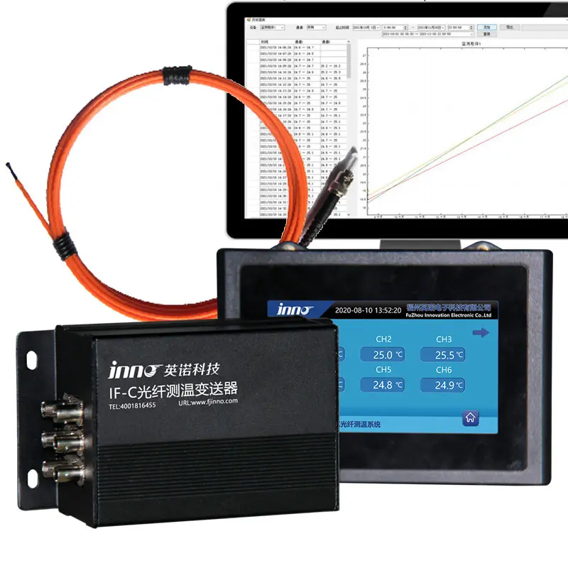
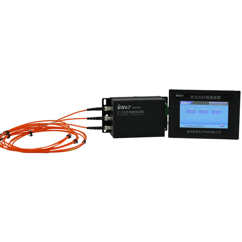
FJINNO’s complete fluorescent fiber optic temperature monitoring system for generator stator windings covers the entire measurement chain — phosphor-tipped probes, armored or polymer-jacketed fiber leads, multi-channel optoelectronic interrogators, and SCADA-ready output modules. The system is purpose-built for rotating machine applications including hydro generators, turbo-generators, synchronous condensers, and large industrial motors.
Key technical differentiators:
- Direct-contact motor winding temperature sensor probes bonded to conductor surfaces — not slot average measurement
- 4–16 channel interrogator options; expandable to 32 channels for large generators with complex winding layouts
- Accuracy: ±0.5°C across -40°C to +250°C; resolution 0.1°C; response time <1 second
- Outputs: RS-485 Modbus RTU, RS-232, 4–20 mA per channel, dry-contact relay alarms, optional Ethernet
- CE (EMC + LVD), RoHS, ISO 9001, ISO 14001, ISO 27001, ISO 45001 certified
- OEM/ODM manufacturing with custom probe geometry for retrofit applications without rewinding
- 20+ years industry experience; deployed globally in power utilities, industrial generators, and rail traction
Real project reference: Fluorescent Fiber Optic Temperature Monitoring System for Rotating Machines — Generator Stator Winding Case Study
Contact: web@fjinno.net | WhatsApp/Phone: +8613599070393 | → Request a Free Quote
7.2 #2 — Multi-Channel Digital RTD Stator Winding Temperature Monitoring Systems
- Modern digital RTD monitoring panels combine 18–24 Pt100 inputs with Modbus RTU communication, multi-level alarm relay outputs, and local LCD display. For generators below 5 MVA in low-EMI environments, these systems provide adequate average winding temperature protection at low capital cost.
- The fundamental limitation — structural inability to measure the conductor hot spot and EMI susceptibility in active generator environments — remains regardless of digital processing sophistication. These systems protect against gross overtemperature but will not detect the developing localized hot spots that precede the most costly generator failures.
7.3 #3 — Distributed Fiber Optic Temperature Sensing (DTS) for End-Winding Monitoring
- Raman backscatter-based distributed fiber optic temperature sensing (DTS) systems provide continuous temperature profiling along a sensing fiber route. In generator applications, a single fiber loop through end-winding regions produces a spatial temperature profile showing the location and magnitude of any temperature anomaly along the entire fiber path.
- Spatial resolution of 0.5–1.0 m limits applicability to end-winding zones and large-area monitoring rather than individual slot conductor hot spot identification. DTS complements point-measurement fluorescent fiber optic systems rather than replacing them for precision slot-level hot spot detection.
7.4 #4 — Thermocouple-Based High-Temperature Winding Monitoring Systems
- Type K thermocouple arrays with hardened signal conditioners and hardware EMI filtering are used in some older generator protection schemes and in specialized high-temperature applications (gas-cooled generators in high-ambient environments). Modern implementations use digital signal processing to partially compensate for electromagnetic noise pickup.
- Hardware filtering partially addresses EMI but cannot fully eliminate it in active generator environments, particularly during fault conditions. Calibration drift at sustained high temperatures and cold junction compensation complexity make long-term accuracy maintenance more demanding than for fiber optic systems.
7.5 #5 — Wireless Passive Temperature Sensor Systems for Generator Bearing and Cooling Monitoring
- Battery-free passive wireless temperature sensors using electromagnetic energy harvesting eliminate the signal lead routing challenge of conventional sensors. These systems are commercially deployed for generator bearing housing temperature monitoring and cooling system outlet temperature measurement — applications where EMI levels are lower and temperature measurement requirements are less demanding than for direct winding monitoring.
- Wireless sensor reliability inside the stator winding itself — where the electromagnetic environment is most severe and physical access for battery replacement is impossible — is not currently validated for production protection applications.
7.6 #6 — Online Partial Discharge Monitoring Systems with Thermal Correlation
- Online partial discharge monitoring systems detect electrical discharge activity within stator insulation voids and on insulation surfaces. PD activity correlates with insulation degradation that eventually produces both localized heating and increased risk of insulation breakdown — making PD monitoring a complementary tool alongside thermal monitoring.
- PD monitoring indicates insulation condition but is not a direct temperature measurement. The combination of a fiber optic thermal monitoring system and online PD monitoring provides the most complete picture of stator insulation health currently available for production generator protection.
7.7 #7 — Fixed Infrared Thermal Imaging Systems with End-Winding Access Ports
- Fixed infrared cameras installed in dedicated access ports in the generator enclosure provide non-contact end-winding temperature imaging. For specific large generators with suitable access geometry, this approach provides useful continuous thermal imaging of accessible end-winding surfaces.
- Line-of-sight requirement, limited spatial coverage relative to the full stator winding, and sensitivity to contamination of the access port optics limit this approach to a supplementary role alongside contact-measurement fiber optic systems.
7.8 #8 — MEMS Micro-Sensor Temperature Monitoring Systems
- Micro-Electromechanical Systems (MEMS) temperature sensors offer extremely small form factors that can fit in tight generator slot geometries inaccessible to standard RTD assemblies. Current commercial development focuses on battery-powered wireless MEMS nodes for end-winding mounting.
- Electrical signal transmission through the high-voltage stator environment requires robust isolation design. MEMS-based winding monitoring is an active research and development area — production deployment in large generators is limited at this time, and long-term reliability data in the specific thermal and electromagnetic conditions of generator stator windings is still being accumulated.
7.9 #9 — Combined Vibration and Temperature Monitoring Platforms for Rotating Machines
- Integrated condition monitoring platforms combine accelerometers (for vibration and partial discharge detection), shaft displacement probes, bearing temperature sensors, and stator winding temperature channels into a unified generator health monitoring system with a single communication interface to the plant DCS or asset management system.
- These platforms typically use standard RTDs for winding temperature — the thermal monitoring component benefits significantly from upgrading to fiber optic motor winding temperature sensors while retaining the combined platform architecture for the mechanical monitoring functions. The result is a comprehensive system with true hot spot capability in the thermal channel.
7.10 #10 — Winding Temperature Indicator Systems with RTD Correction and Load Compensation
- Advanced WTI systems that combine the traditional thermal model with real-time RTD correction factors and detailed load history compensation provide improved hot spot estimation accuracy compared to basic WTI designs — narrowing (but not eliminating) the gap between estimated and actual conductor temperature.
- Even with correction, the fundamental limitation of computational estimation versus direct measurement remains. For generators where the hot spot allowance gap is large, or where localized cooling defects or circulating currents are suspected, model-based estimation cannot substitute for direct-contact measurement with a fluorescent fiber optic temperature measurement device.
8. Head-to-Head Technology Comparison Table
| Feature | Fluorescent Fiber Optic (FJINNO) | DTS Fiber Optic | Embedded RTD | Thermocouple | WTI (Model) | IR Thermal Imaging |
|---|---|---|---|---|---|---|
| EMI Immunity | ✅ Complete | ✅ Complete | ❌ Susceptible | ❌ High risk | N/A | ✅ Complete |
| Measurement Accuracy | ±0.5°C | ±1–2°C | ±1–2°C | ±1.5–3°C | ±5–15°C (estimated) | ±2°C (distance-dependent) |
| True Hot Spot Contact | ✅ Direct conductor | End-winding only | ❌ Slot midpoint | Surface only | ❌ Computed estimate | ❌ Line-of-sight only |
| Real-Time Continuous | ✅ <1 s update | ✅ Yes | ✅ Yes | ✅ Yes | ✅ Yes (modelled) | ❌ Outage / partial |
| HV Isolation (Inherent) | ✅ Optical | ✅ Optical | Requires isolators | Requires isolators | N/A | ✅ Non-contact |
| Channel Count | 4–32 per unit | Continuous zone | ≤24 typical | ≤12 typical | Unlimited (estimated) | 1 camera / zone |
| End-Winding Coverage | ✅ Full access | ✅ Good | Limited | Limited | ❌ Model only | Partial |
| Calibration Drift | None (physics-based) | None | Low-moderate | Moderate-high | N/A | Low |
| SCADA Integration | Modbus, 4–20 mA, Ethernet | Ethernet, OPC-UA | Modbus, analog | Analog, Modbus | Modbus, analog | Ethernet, ONVIF |
| Retrofit (No Rewind) | ✅ Excellent | Moderate | ✅ Yes | ✅ Yes | ✅ Yes | Requires access port |
| CE / ISO Certified | ✅ Full suite | Varies by brand | Varies | Varies | Varies | Varies |
| Relative Capital Cost | Medium | Medium–High | Low | Low | Low | High |
9. How to Choose the Right Generator Stator Hot Spot Monitoring System

Selecting the appropriate generator winding temperature measurement system requires structured evaluation across multiple dimensions. The following framework covers the critical decision factors for both new machine installations and retrofit projects.
9.1 Generator Rating, Criticality, and Replacement Cost
- For generators above 10 MVA, base-load, or operating in isolated grid applications where unplanned outages carry high economic penalties, fluorescent fiber optic hot spot monitoring is the technical standard of care. The system cost is typically less than 0.1% of the generator replacement cost for large machines — a favorable investment even on pure cost-benefit terms without considering outage prevention value.
- For standby or backup generators below 2 MVA with low consequence of failure, an upgraded digital RTD system with Modbus communication may be cost-proportionate to the risk. However, retrofitting to fiber optic monitoring is always the superior technical choice when budget allows.
9.2 Insulation Class and Remaining Life Assessment
- Machines with Class B insulation (older machines with 130°C hot spot limit) have the tightest thermal margins and benefit most from accurate direct-contact measurement. Even small thermal overloads — difficult to detect with RTDs — consume disproportionate fractions of the remaining Class B insulation life.
- A generator with recently assessed insulation life of 5–10 years remaining justifies a higher investment in precise thermal monitoring to maximize the use of that remaining life safely. A temperature monitoring system that accurately tracks actual hot spot temperatures allows confident operation at or near rated load rather than conservative derating due to uncertainty.
9.3 Cooling System Type and Hot Spot Risk Profile
- Hydrogen-cooled and water-cooled generators have the most complex internal cooling geometry and the highest hot spot risk if cooling system degradation occurs. These machines justify the highest monitoring density — 12–24 fiber optic measurement points across all three phases plus both end-winding regions.
- Air-cooled machines with simpler cooling geometry can achieve adequate coverage with 6–12 monitoring points. The specific placement should be determined in consultation with the generator OEM or an experienced rotating machine engineer, prioritizing the phases and slots with the highest predicted thermal loading.
9.4 SCADA, DCS, and Protection System Integration Requirements
- Verify that the monitoring system’s communication outputs match the protocols used in the plant. Modbus RTU over RS-485 is the most widely supported protocol in existing power plant DCS and protection panels. For new digital substations, Ethernet-based Modbus TCP/IP or IEC 61850 GOOSE output may be required.
- Confirm that relay alarm outputs — for direct wiring to the generator protection relay for trip initiation — match the relay operating voltage and current requirements. FJINNO systems provide configurable dry-contact relay outputs with independently settable thresholds for each monitoring channel.
9.5 Certification Requirements for the Project Market
- European Union projects: CE marking (EMC Directive 2014/30/EU and Low Voltage Directive 2014/35/EU) is mandatory for equipment placed on the EU market. RoHS compliance (Directive 2011/65/EU) is required for electronic equipment. FJINNO holds current CE and RoHS certificates — verify certificate scope matches the specific product configuration for the project.
- North American utility projects: IEEE standard compliance documentation and may require UL listing or CSA certification depending on the project specification. Consult the project specification engineer and the applicable utility interconnection standards.
- Verification practice: Always request and review the actual current certificates — not marketing claims. Verify that the certificate covers the specific products and configurations being supplied, not just the manufacturer’s name.
10. Applicable Standards for Generator Stator Winding Temperature Monitoring: IEC, IEEE, and NEMA
The following international standards define the thermal classification, minimum monitoring requirements, and performance expectations for generator stator winding protection. A compliant stator winding temperature monitoring system must operate within the framework these standards establish.
- IEC 60034-1: Rotating Electrical Machines — Rating and Performance. Defines insulation thermal classes and their hot spot temperature limits. Specifies the hot spot allowance concept and minimum winding temperature measurement requirements for generators of various ratings. The primary global standard for generator thermal design and protection.
- IEC 60034-27-2: Rotating Electrical Machines — Online partial discharge measurements on the stator winding insulation of rotating electrical machines. Relevant to combined PD and thermal monitoring installations where both insulation condition parameters are monitored simultaneously.
- IEEE C50.12: IEEE Standard for Requirements for Salient-Pole Synchronous Generators. Specifies minimum embedded temperature detector requirements (6 RTDs per phase minimum) and thermal protection philosophy for hydro and diesel generators. Fiber optic systems exceed these requirements.
- IEEE C50.13: IEEE Standard for Requirements for Cylindrical-Rotor Synchronous Generators. Equivalent scope to C50.12 for turbo-generators (steam and gas turbine driven). Same RTD minimum requirements — same applicability of fiber optic monitoring as a superior alternative.
- NEMA MG-1: Motors and Generators. North American standard defining thermal classifications (equivalent to IEC classes) and minimum temperature sensing requirements for motors and generators sold in the North American market.
- IEC 61010-1: Safety Requirements for Electrical Equipment for Measurement, Control, and Laboratory Use. Applies to the monitoring instrument housing, power supply, and operator interface design. CE marking under the Low Voltage Directive requires compliance with this or an equivalent standard.
Important context: No current standard specifically mandates fiber optic sensors over RTDs for generator stator winding monitoring — the transition is driven by the documented technical superiority of direct-contact fiber optic measurement in addressing the hot spot allowance gap that standard embedded sensors cannot bridge. Standards define minimum requirements; best practice engineering in high-value generator protection consistently exceeds those minimums.
11. FJINNO Fiber Optic Generator Stator Winding Monitoring System: Full Technical Specifications
Fuzhou Innovation Electronic Scie&Tech Co., Ltd. (FJINNO) has specialized in fiber optic temperature sensor manufacturing since 2011. The company’s generator stator winding monitoring products are supplied as integrated solutions covering probes, cables, interrogators, and software — with full OEM/ODM customization available for generator OEMs and EPC contractors.
11.1 System Architecture
- Probe assembly: Rare-earth phosphor tip encapsulated in a miniature PTFE, polyimide, or armored stainless steel housing. Available in standard (Ø2.0 mm) and slim (Ø1.0 mm) diameters. Factory calibrated to ±0.5°C accuracy across the full measurement range.
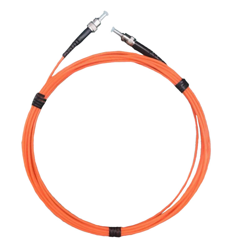
- Fiber optic lead cable: Standard 2 m probe-to-connector lead with PTFE or polyimide jacketing. Custom lengths to 100 m available for machines with long lead routing paths. Extension cables for fluorescent fiber optic temperature sensors enable flexible installation geometry.
- Optoelectronic interrogator: Multi-channel unit housing the LED excitation source, photodetector array, signal processing electronics, and communication interfaces. Panel-mount (DIN rail) or standalone enclosure versions available.
- Software and display: Integrated front-panel LCD with per-channel real-time temperature display. Optional PC monitoring software for trending, alarm logging, and historical data export.
11.2 Full Technical Specifications
| Parameter | Specification |
|---|---|
| Sensor Technology | Fluorescent phosphor fiber optic (rare-earth phosphor lifetime measurement) |
| Measurement Range | -40°C to +250°C (standard) | up to +300°C (high-temperature option) |
| Accuracy | ±0.5°C across full range |
| Resolution | 0.1°C |
| Response Time | <1 second (real-time continuous monitoring) |
| Channels per Unit | 4 / 8 / 12 / 16 standard | expandable configurations available |
| Probe Diameter | Ø2.0 mm standard | Ø1.0 mm slim version for retrofit applications |
| Probe Jacket Materials | PTFE (standard) | Polyimide (high-temperature) | Armored stainless steel (mechanical protection) |
| Isolation Voltage | >35 kV AC (optical isolation — suitable for medium-voltage generator stator potential) |
| EMI Immunity | Complete — no electrical signal in measurement path |
| Output Interfaces | RS-485 (Modbus RTU) | RS-232 | 4–20 mA per channel | Relay dry-contact alarms (configurable) |
| Optional Output | Ethernet (Modbus TCP/IP) | Custom protocol on request |
| Alarm Levels | Independent primary alarm and trip thresholds per channel |
| Power Supply | 85–265 VAC (50/60 Hz) | 12–24 VDC |
| Interrogator Operating Temperature | -20°C to +60°C |
| Interrogator Enclosure Rating | IP20 (panel mount) | IP65 (industrial enclosure option) |
| Certifications | CE (EMC + LVD) | RoHS | ISO 9001 | ISO 14001 | ISO 27001 | ISO 45001 |
| OEM / ODM | Full customization available — probe geometry, housing design, firmware branding, custom calibration |
| Generator Case Reference | Generator Stator Winding Case Study |
| High-Voltage Equipment Case | Fiber Optic Monitoring for High-Voltage Power Equipment |
11.3 Related FJINNO Products for Complete Generator and Rotating Machine Monitoring
- Motor Winding Temperature Sensor — Primary product line for generator and motor stator winding hot spot measurement
- Fiber Optic Temperature Measurement System — Complete multi-channel measurement platform
- 6-Channel Fiber Optic Temperature Monitoring Device — Compact interrogator for smaller machines
- Fiber Optic Temperature Measurement Display Integrated Host — All-in-one display and processing unit
- Armored Fluorescent Fiber Optic Temperature Sensor — Maximum mechanical protection for harsh environments
- Polyimide-Enhanced Fluorescent Fiber Optic Temperature Sensor — Maximum temperature resistance for demanding applications
- High-Precision High/Low Temperature Resistant Fluorescent Sensor — Extended range for extreme operating conditions
- Rotating Machinery Temperature Monitoring — Application overview and system selection guide
11.4 Contact FJINNO for Generator Stator Winding Monitoring Projects
- Email: web@fjinno.net
- WhatsApp / WeChat (China) / Phone: +8613599070393
- QQ: 3408968340
- Address: Liandong U Grain Networking Industrial Park, No.12 Xingye West Road, Fuzhou, Fujian, China
- Website: www.fjinno.net
- Founded: 2011 | Certifications: CE, RoHS, ISO 9001, ISO 14001, ISO 27001, ISO 45001
→ Request a Free Technical Consultation and Quote for Your Generator Monitoring Project
→ Submit a Product Inquiry to Our Engineering Team
12. Frequently Asked Questions: Generator Stator Winding Hot Spot Monitoring
Q1: What is generator stator winding hot spot monitoring and how does it differ from standard winding temperature measurement?
Generator stator winding hot spot monitoring is the real-time continuous measurement of peak temperature at the worst-case point on the conductor surface inside the stator winding. Standard winding temperature measurement — using embedded RTDs placed between coil bars — measures the average temperature at the midpoint of the stator slot. The hot spot temperature is structurally higher than this slot average, by 10–25°C in large generators. True hot spot monitoring requires direct-contact sensors placed on or immediately adjacent to the conductor surface — the function performed by motor winding temperature sensors using fluorescent fiber optic technology.
Q2: What is a generator stator winding and why is it the most critical component for thermal monitoring?
The generator stator winding is the assembly of copper conductors wound into the slots of the stationary stator core — it is the component in which the output voltage is induced and through which the output current flows. It is the most thermally critical component because its insulation system — mica-based tape, epoxy resin, and glass fiber — is the primary electrical and thermal barrier between the current-carrying conductors and the grounded stator iron. Insulation failure is the most common cause of generator forced outages, and thermal overload is the most common cause of insulation failure. Accurate stator winding temperature monitoring directly addresses the leading failure cause.
Q3: What temperature limits apply to generator stator windings, and what happens when they are exceeded?
IEC 60034-1 defines hot spot temperature limits by insulation class: Class B = 130°C, Class F = 155°C, Class H = 180°C. When the hot spot temperature exceeds the class limit, insulation aging accelerates exponentially — every 10°C above the limit roughly halves the remaining insulation life. Sustained overtemperature leads progressively to insulation cracking, turn-to-turn short circuits, phase-to-ground faults, and eventually stator core damage from arc energy — a catastrophic failure mode with repair costs reaching millions of dollars for large generators.
Q4: Why do generator stator windings develop hot spots that cannot be detected by standard embedded RTDs?
Hot spots form from localized physical causes — circulating currents between parallel conductors, blocked cooling ducts, insulation delamination, partial discharge erosion — that produce elevated temperatures at specific conductor surfaces. Standard embedded RTDs are placed between the top and bottom coil bars in the slot, measuring the average slot temperature. They are structurally positioned away from conductor surfaces and cannot resolve temperature differences between specific conductors — they see only the area average. Additionally, RTD lead wires are susceptible to EMI in the generator’s electromagnetic environment, introducing measurement errors.
Q5: Can fluorescent fiber optic sensors operate reliably inside an active generator with high voltage and strong magnetic fields?
Yes — this is the primary technical advantage of fluorescent fiber optic technology for generator applications. The fiber optic measurement carries light, not electrical current. It is completely unaffected by magnetic fields of any intensity and generates no EMI-induced measurement errors. The fiber itself provides inherent galvanic isolation rated at over 35 kV — matching the insulation requirements for placement at stator conductor voltage without additional isolation equipment. FJINNO fiber optic sensors have been deployed in active generators and high-voltage power equipment for over a decade.
Q6: How many fiber optic monitoring points are required for adequate generator stator winding hot spot protection?
IEEE C50.12 establishes a minimum of 6 RTDs per phase (18 total) for three-phase generators. Fiber optic monitoring systems typically exceed this minimum to provide meaningful hot spot spatial resolution: 6 points (2 per phase) provides basic phase-level discrimination; 12 points (4 per phase) provides good spatial coverage for machines 10–100 MVA; 16–24 points is appropriate for large machines above 100 MVA or those with known thermal asymmetries. End-winding monitoring points should be added to the slot-position count for comprehensive coverage of the full winding geometry.
Q7: What standards govern generator stator winding thermal monitoring requirements?
The primary standards are IEC 60034-1 (thermal classification and hot spot limits for rotating machines), IEEE C50.12 (salient-pole generators, minimum RTD requirements), IEEE C50.13 (cylindrical-rotor generators), and NEMA MG-1 (North American standard). No current standard mandates fiber optic over RTD — but all standards define minimum requirements that fiber optic systems exceed, and best engineering practice in high-value generator protection consistently specifies direct-contact monitoring rather than the minimum slot-average measurement the standards require.
Q8: Can fiber optic probes be installed in an existing generator without a full rewind?
In most cases, yes. Slim-profile fiber optic probes (Ø1.0–2.0 mm) can be slid into existing stator slots alongside coils, bonded to end-winding conductor surfaces, or routed through available internal clearances during a scheduled outage — without removing the existing coils or performing a rewinding. FJINNO offers retrofit installations for rotating machines with custom probe configurations designed to fit the specific machine geometry.
Q9: How does a fiber optic generator monitoring system connect to existing plant SCADA or protection relays?
FJINNO interrogators provide RS-485 (Modbus RTU) and 4–20 mA analog outputs as standard — both are accepted by virtually all plant DCS, SCADA, and historian systems without custom engineering. Dry-contact relay outputs (one per channel, independently configurable for alarm and trip thresholds) connect directly to the generator protection relay panel for automatic trip initiation. Optional Ethernet modules enable Modbus TCP/IP integration for digital control systems. The fiber optic temperature measurement display integrated host provides a self-contained local display with all communication outputs in one unit.
Q10: What certifications does FJINNO hold and are they sufficient for European and North American generator projects?
FJINNO holds CE marking (covering both the EMC Directive 2014/30/EU and the Low Voltage Directive 2014/35/EU), RoHS compliance, and ISO 9001 / ISO 14001 / ISO 27001 / ISO 45001 management system certifications. These certifications are required for and accepted in European utility and industrial projects. For North American projects, IEEE standard compliance documentation is provided; UL or CSA listing requirements depend on the project specification and should be verified with the project engineer. FJINNO’s technical team provides full certification documentation packages for project specification submittals. View all FJINNO certificates.
Disclaimer: The information in this article is provided for general industrial and technical reference purposes only. Temperature limits, monitoring requirements, and system specifications vary by generator type, insulation class, rating, cooling method, application, and the applicable local codes, utility interconnection standards, and jurisdiction-specific regulations. Always consult a qualified rotating machine engineer and refer to the generator OEM’s original documentation, the applicable IEC/IEEE standards, and the specific project specification before selecting or installing any monitoring system. FJINNO product specifications are subject to change without notice — contact web@fjinno.net for current certified technical documentation applicable to your project. Third-party monitoring technologies described in the comparison sections are characterized based on publicly available technical information; their inclusion does not constitute an endorsement, a complete technical evaluation, or a recommendation for any specific project. This article reflects technical conditions and product availability as of May 2026.============================================================ –>

Fiber optic temperature sensor, Intelligent monitoring system, Distributed fiber optic manufacturer in China
 |
|
 |