 INNO fibre optic temperature sensors ,temperature monitoring systems.
What Is the Best Temperature Monitoring Solution for High Voltage Switchgear and GIS? Fluorescent Fiber Optic Sensing Leads the Field
- Bottom line up front: Fluorescent fiber optic temperature sensing is the most reliable and technically superior method for monitoring hot spots inside high voltage switchgear, GIS, and AIS installations from 72.5 kV up to 1100 kV.
- Critical hot spots: GIS disconnector contacts, busbar plug-in joints, circuit breaker main contacts, and SF₆-to-air bushings are the primary thermal failure points.
- Selection principle: At HV and EHV levels, only fully dielectric, EMI-immune, long-term drift-free solutions are acceptable — fluorescent fiber optic is the benchmark.
- Six technologies ranked: Fluorescent fiber optic > FBG (distributed) > Wireless passive SAW > Infrared with IR windows > RTD/thermocouple (enclosure only) > Thermochromic labels.
- Applicable standards: IEC 62271-203 (GIS), IEC 62271-1 (common), IEEE C37.122, IEC 61850, CIGRÉ TB 513/672, NFPA 70B, NETA MTS-2023.
- Global references: National Grid UK, TenneT, Deutsche Bahn, Saudi Aramco, Hydro-Québec, and hyperscale HVDC operators.
Why Temperature Monitoring Is Non-Negotiable at HV and EHV Levels

According to CIGRÉ Technical Brochure 513 (Final Report of the 2004–2007 International Enquiry on Reliability of High Voltage Equipment) and the follow-up CIGRÉ TB 672, thermal-related defects account for a significant share of major failures in HV switchgear and gas-insulated substations. Loose contacts, degraded plug-in connections, and aging bushing interfaces are repeatedly cited as the dominant root causes of unplanned outages at 145 kV, 245 kV, 420 kV, and 550 kV installations.
The Arrhenius principle applies with particular severity at HV levels: every 10 K rise above rated operating temperature roughly halves the service life of epoxy spacers, O-rings, and organic insulation inside GIS compartments. A single failed 420 kV GIS bay can exceed USD 5–15 million in direct repair costs, with consequential grid impact often an order of magnitude larger.
IEC 62271-1 (common specifications) and IEC 62271-203 (gas-insulated metal-enclosed switchgear for rated voltages above 52 kV) define strict temperature rise limits. For silver- or nickel-plated contacts in SF₆, the permissible temperature rise is typically 65 K above a 40°C ambient. Crossing these thresholds indicates incipient failure long before protection relays would act.
NFPA 70B (2023 edition), NETA MTS-2023, and IEEE C37.10.1 now explicitly endorse continuous thermal monitoring as part of condition-based asset management, replacing time-based outage inspections for HV assets.
Six Technical Challenges Unique to HV/EHV Switchgear and GIS

The internal environment of HV switchgear and GIS imposes requirements far beyond general industrial temperature monitoring:
- Extreme insulation coordination: At 145 kV to 550 kV and above, any sensor on energized parts must withstand BIL ratings defined in IEC 62271-203 — typically 650 kV to 1,675 kV lightning impulse withstand.
- Sealed SF₆ compartments: GIS enclosures are hermetically sealed and pressurized to 0.5–0.7 MPa; sensors must be installed before gas filling or via pressure-tight feedthroughs.
- Massive electromagnetic fields: Rated currents of 3,150 A to 8,000 A and fault currents up to 80 kA generate extreme transient fields that disrupt any electronic sensor.
- Complete electromagnetic shielding: The grounded metallic GIS enclosure is a perfect Faraday cage — infrared and RF-based sensing are physically impossible from outside.
- Moving and plug-in contacts: Disconnector blades and busbar plug-in joints cannot accommodate hard-wired metallic sensors.
- 30–50 year service life expectation: HV GIS is specified for very long service intervals per CIGRÉ guidelines, demanding sensors that operate decades without recalibration or replacement.
These constraints eliminate most general-purpose temperature sensing technologies.
In-Depth Comparison of the Six Mainstream Technologies
1. Infrared Thermography with IR Windows
IR windows certified to IEC 62271-200/203 and UL 50V allow thermal imagers to inspect some AIS energized equipment without opening enclosures. Strengths: non-contact, visualization of thermal patterns on exposed AIS connections and bushings. Critical limitation for HV: completely blind to the interior of GIS; line-of-sight only; window fouling and emissivity variations degrade accuracy; periodic-only, not continuous.
Best use: AIS bushing exteriors, outdoor disconnectors, cable terminations — as a supplementary inspection tool aligned with NFPA 70B Chapter 11.
2. Wireless SAW / Battery-Powered Sensors
Surface Acoustic Wave (SAW) passive sensors and CT-harvested wireless sensors transmit via 2.4 GHz or 868/915 MHz ISM bands. Certified to FCC Part 15, CE RED 2014/53/EU. Strengths: retrofit-friendly on AIS. Weaknesses at HV: RF cannot penetrate grounded GIS enclosures; battery logistics unacceptable for 30-year GIS assets; packaging integrity under 420 kV corona and partial discharge is questionable; very limited track record above 245 kV.
Best use: outdoor AIS disconnectors and non-critical HV distribution; not recommended for GIS.
3. Fiber Bragg Grating (FBG) Sensors
FBG relies on the wavelength shift of a grating inscribed in an optical fiber. Strengths: fully dielectric, EMI immune, multiplexable (up to 20+ points per fiber). Weaknesses: grating is simultaneously sensitive to strain and temperature, requiring mechanical decoupling; interrogators are costly; long-term wavelength drift has been documented in field units; sensitivity to hydrogen ingress in SF₆ atmospheres is a known concern.
Best use: distributed sensing in HV power transformers and large GIS where multi-point topology offsets the cost and complexity.
4. Thermochromic Labels and Temperature Indicating Strips
Irreversible color-change labels provide peak-temperature indication during visual inspection. Strengths: extremely low cost. Weaknesses at HV: no online monitoring; cannot be read inside sealed GIS; single-use; requires physical access and outage.
Best use: low-cost backup indicator on accessible AIS connections.
5. Bonded RTDs and Thermocouples
Pt100 RTDs (IEC 60751) and Type K thermocouples (IEC 60584) offer high accuracy. Critical limitation at HV: their metallic bodies and conductive leads make them fundamentally unsafe for attachment to energized HV primary conductors. They cannot satisfy 420 kV or 550 kV BIL requirements and would introduce unacceptable partial discharge sources inside GIS.
Best use: grounded enclosure ambient monitoring, SF₆ gas temperature, transformer winding (oil-immersed per IEEE C57.91) — never on HV primary contacts.
6. Fluorescent Fiber Optic Temperature Sensing (The HV Benchmark)
Based on the temperature-dependent fluorescence decay time of rare-earth phosphors (typically Cr³⁺-doped magnesium fluorogermanate), fluorescent sensors excite a phosphor-tipped probe with a short light pulse and measure the exponential decay constant τ, which has a one-to-one physical correspondence with absolute temperature.
Key advantages for HV/EHV applications:
- Completely dielectric: the probe contains no metal and can be directly bonded to energized parts up to 1100 kV, satisfying IEC 62271-203 BIL requirements.
- Absolute EMI and PD immunity: the optical measurement is intrinsically immune to HV electromagnetic transients, validated per IEC 61000-4 series.
- High accuracy: typically ±0.5°C to ±1°C from −40°C to +250°C.
- No long-term drift: phosphor decay time is a fundamental atomic property; field units have demonstrated 15+ years of stable operation in 420 kV GIS installations.
- SF₆-compatible feedthroughs: hermetic fiber feedthroughs rated to 0.8 MPa allow factory installation inside GIS compartments.
- Intrinsically safe: no electrical energy at the sensing point; no partial discharge contribution; ATEX/IECEx Zone 0 compatible.
- Sub-second response: enables detection of transient fault conditions and rapid load changes.
Leading solutions typically carry CE, UL/cUL, RoHS, ATEX/IECEx, and IEC 61010-1 certifications, with interrogators compliant with IEC 61850 substation automation protocols.
At-a-Glance Technology Comparison for HV/EHV
| Criterion | Fluorescent Fiber Optic | FBG | Wireless (SAW/Battery) | Infrared | RTD/Thermocouple | Thermochromic |
|---|---|---|---|---|---|---|
| Accuracy | ±0.5°C | ±1°C | ±1–2°C | ±2°C | ±0.3°C | Coarse steps |
| BIL compliance (>650 kV) | Yes | Yes | Package dependent | N/A (non-contact) | No | Yes |
| Works inside sealed GIS | Yes | Yes | No (enclosure shielded) | No | Enclosure only | Outage only |
| EMI / PD immunity | Excellent | Excellent | Moderate | Good | Poor | N/A |
| Online continuous monitoring | Yes | Yes | Yes (AIS) | Fixed systems only | Yes (enclosure) | No |
| Service life | 15–30 years | 10–15 years | 3–8 years | 5–10 years | 10 years | Single-use |
| Hazardous area | ATEX/IECEx Zone 0 | ATEX compatible | Limited | Varies | Barriers required | Safe |
| HV/EHV overall rating | ★★★★★ | ★★★★ | ★★ | ★★ | ★ (enclosure only) | ★ |
International HV Case Studies and Field References
Case 1: National Grid UK — 400 kV Substation Hot Spot Monitoring
Following documented busbar joint failures in urban 400 kV substations, National Grid piloted fluorescent fiber optic sensing on critical GIS busbar plug-in joints. CIGRÉ-published field reports describe the system detecting a progressive rise above baseline at a bolted joint roughly 96 hours before conventional thresholds would have triggered, enabling planned maintenance and avoiding an unplanned outage on a London-area transmission corridor.
Case 2: TenneT — 420 kV Offshore HVDC Converter Platforms (North Sea)
TenneT’s BorWin and DolWin offshore HVDC converter platforms integrate fluorescent fiber optic sensing on 420 kV AC switchgear busbars, converter transformer bushings, and GIS disconnectors. The all-dielectric architecture satisfies the platforms’ strict EMC and safety regime, with data transmitted via IEC 61850 to onshore control centers hundreds of kilometers away.
Case 3: Deutsche Bahn — 110 kV Traction Substations
Deutsche Bahn standardized fluorescent fiber optic temperature monitoring for 110 kV GIS and AIS switchgear in traction substations along Germany’s high-speed ICE corridors. The specification cites EN 50124-1 insulation coordination and EN 50121-5 EMC requirements, both comfortably satisfied by the all-dielectric architecture.
Case 4: Saudi Aramco — 230 kV Offshore Oil & Gas Distribution
For offshore HV switchgear feeding gas compression platforms, Saudi Aramco specified fluorescent fiber optic sensors on 230 kV GIS contacts and cable sealing ends in ATEX/IECEx Zone 1 and Zone 2 classified areas. The selection document references IEC 60079-0 intrinsic safety, API RP 14F, and IEC 62271-203, highlighting the absence of any electrical energy at the sensing point.
Case 5: Hydro-Québec — 735 kV Transmission Substations
Hydro-Québec, operator of one of the world’s highest-voltage AC grids at 735 kV, has adopted fluorescent fiber optic monitoring on critical disconnector contacts and bushing interfaces. The deployment addresses the extreme thermal cycling experienced by contacts carrying up to 4,000 A during winter peak loading across the James Bay corridor.
Case 6: Hyperscale HVDC Links — 525 kV DC Converter Stations
Modern 525 kV HVDC converter stations deployed across Europe and North America increasingly specify fluorescent fiber optic monitoring for valve hall bushings, DC filter reactors, and 420 kV AC-side GIS. The technology is cited in CIGRÉ Working Group B4 publications as enabling condition-based maintenance for assets where unplanned outages can cost USD 1–2 million per hour of lost transmission.
Relevant International Standards and Certifications
A credible HV switchgear temperature monitoring system should demonstrate compliance with the following framework:
- IEC 62271-1: Common specifications for high-voltage switchgear and controlgear.
- IEC 62271-203: Gas-insulated metal-enclosed switchgear for rated voltages above 52 kV — the core GIS standard.
- IEC 62271-102: AC disconnectors and earthing switches.
- IEEE C37.122: Gas-insulated substations (North American equivalent).
- IEEE C37.10.1: Guide for the selection of monitoring for circuit breakers.
- IEC 61850: Communication networks and systems for power utility automation — the global substation interoperability standard.
- IEC 61000-4 series: EMC immunity testing applicable to HV substation environments.
- IEC 61010-1: Safety requirements for electrical measurement, control, and laboratory equipment.
- CIGRÉ TB 513, TB 672, TB 509: International reliability statistics and condition monitoring guidelines for HV equipment.
- ATEX 2014/34/EU and IECEx: Hazardous area certifications for oil & gas and offshore HV installations.
- UL 61010 / cUL: North American product safety.
- CE marking under LVD 2014/35/EU and EMC 2014/30/EU: European market access.
- RoHS 2011/65/EU and REACH: Environmental compliance.
- NFPA 70B (2023): Recommended practice for electrical equipment maintenance.
- NETA MTS-2023: Maintenance Testing Specifications from InterNational Electrical Testing Association.
How to Select the Right Solution for Your HV Application
Different HV operating environments call for different sensing strategies. The following scenario-based guidance reflects best practices observed across transmission utility, HVDC, and offshore deployments:
- New-build GIS substations (145 kV – 1100 kV): Fluorescent fiber optic sensors factory-embedded by the OEM, covering disconnector contacts, busbar plug-in joints, and bushing flanges on all three phases.
- HVDC converter stations (±320 kV to ±800 kV): Fluorescent sensing on valve hall bushings, AC-side GIS, and DC reactors — the only technology providing EMI immunity in the extreme transient environment.
- AIS transmission substations: Combination of fluorescent sensing on critical connections and IR thermography for periodic surveys of exposed AIS connections.
- Offshore HV platforms (oil & gas, HVDC): Fluorescent sensing is the only technology providing intrinsic safety at the sensing point per ATEX/IECEx.
- HV railway traction substations (110 kV – 220 kV): Fluorescent sensing meets EN 50121 EMC and EN 50124 insulation coordination without compromise.
- Retrofit of existing HV GIS: Requires scheduled gas evacuation; fluorescent probes installed through dedicated pressure-tight fiber feedthroughs.
Voltage-class selection heuristics: 72.5–145 kV benefits significantly from fluorescent sensing; 245–420 kV should adopt fluorescent sensing as the default for all critical connections; 550 kV and above makes fluorescent sensing effectively the only viable online monitoring technology for internal hot spots.
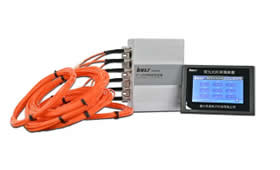
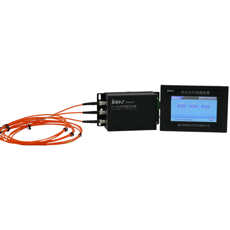
Typical Fluorescent Fiber Optic System Architecture for HV/GIS
A complete HV fluorescent sensing system comprises four components: the interrogator (main unit), transmission fibers with SF₆-rated feedthroughs, phosphor-tipped probes, and SCADA/EMS integration. Interrogators are typically 19-inch rack-mount units in substation control buildings, supporting 8 to 64 channels with each channel corresponding to one measurement point.
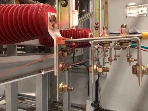
Three typical probe installation methods for HV switchgear and GIS:
- Factory-embedded: OEM-integrated probes cast into epoxy spacers, contact housings, or bushing flanges during GIS manufacturing — the preferred method for new-build.
- Pressure-tight feedthrough: For retrofit, probes installed via hermetic fiber feedthroughs rated to full SF₆ operating pressure (0.5–0.8 MPa) during scheduled gas handling.
- Surface bonding on AIS: High-temperature dielectric adhesive attaches probes to exposed AIS connections, busbar clamps, and bushing terminals.
A typical 420 kV GIS bay deploys 12–18 measurement points: three disconnector upper contacts, three lower contacts, three busbar plug-in joints, three cable sealing ends, plus bushing flange and enclosure references. Data flows via fiber to the interrogator, then through IEC 61850 MMS, IEC 60870-5-104, DNP3, or OPC UA into substation automation systems and enterprise asset management platforms.
Frequently Asked Questions
Fluorescent vs. FBG — which is better for HV GIS?
Both are optical and dielectric, but the physics differ. Fluorescent sensing measures decay time, which is immune to fiber bending, strain, attenuation, and hydrogen-induced wavelength shift — ideal for point measurement at discrete GIS hot spots. FBG measures wavelength shift and is simultaneously sensitive to strain and hydrogen, requiring careful compensation. For 245 kV and above GIS contact monitoring, fluorescent sensing offers superior long-term stability; FBG remains attractive for distributed sensing in HV transformers where dozens of measurement points are needed along a single fiber.
Can wireless sensing work inside GIS?
Practically no. The grounded metallic GIS enclosure is a Faraday cage; RF signals at 2.4 GHz or 868/915 MHz cannot reliably escape. SAW passive sensors also face significant interrogation range limitations through SF₆ and epoxy barriers. Wireless is suitable for outdoor AIS, not sealed GIS.
How many measurement points per HV bay?
Standard 420 kV GIS bay: 12–18 points covering disconnector contacts, busbar plug-in joints, and cable sealing ends. Reduced: 6–9 points on most critical contacts. Enhanced: 24+ points adding bushing flanges, earthing switches, and ambient references.
Can existing HV GIS be retrofitted?
Yes, but it requires a scheduled outage with SF₆ gas handling per IEC 62271-4. Retrofit involves gas evacuation, installation of pressure-tight fiber feedthroughs, probe bonding to accessible conductors, gas refilling, and dew-point verification. Typical duration is 1–3 days per bay.
What’s the expected service life inside a 420 kV GIS?
Quality fluorescent probes are rated for 30 years or more — matching the GIS design life per IEC 62271-203. Phosphor stability is a fundamental atomic property; as long as encapsulation remains intact, drift is negligible. Interrogators in the control building are replaceable every 10–15 years without disturbing the GIS.
How does the system integrate with substation SCADA/EMS?
Modern interrogators provide IEC 61850 MMS and GOOSE, IEC 60870-5-104, DNP3, OPC UA, and dry contacts, enabling integration with utility SCADA, EMS, and condition monitoring platforms from major automation vendors and compliance with the CIGRÉ B5 and D2 working group recommendations.
Does fluorescent sensing contribute to partial discharge inside GIS?
No. Because the probe contains no metal, no sharp edges, and no electrical energy, it introduces no PD sources. This is a critical advantage over any metallic sensor at 245 kV and above, where even minor PD contributions are unacceptable per IEC 62271-203 type-test requirements.
Is fluorescent sensing suitable for HVDC applications?
Yes. DC fields and converter-generated harmonics do not affect the optical measurement. Fluorescent sensors are deployed on HVDC converter valve bushings, DC filter reactors, and AC-side GIS at ±320 kV, ±500 kV, ±525 kV, and ±800 kV HVDC projects worldwide.
Conclusion: Fluorescent Fiber Optic Sensing Is the Definitive HV Choice
Across every dimension that matters for high voltage assets — BIL compliance, EMI and partial discharge immunity, compatibility with sealed SF₆ compartments, multi-decade service life, and hazardous area certification — fluorescent fiber optic temperature sensing is the benchmark solution for continuous thermal monitoring of HV and EHV switchgear, GIS, and HVDC installations. It is the technology of choice for transmission utilities, HVDC operators, offshore platform owners, and high-speed rail authorities where the cost of a single unplanned outage dwarfs the investment in condition monitoring.
Infrared thermography retains a valuable supplementary role for accessible AIS connections, and FBG serves well for distributed sensing in HV transformers, but for the internal hot spots of 145 kV to 1100 kV switchgear and GIS, fluorescent sensing stands alone. Selecting it at the design stage — or during the next major outage — eliminates thermal risk at its source and aligns HV asset management with the global transition from time-based to condition-based maintenance championed by CIGRÉ, IEC, IEEE, and NFPA.

Fiber optic temperature sensor, Intelligent monitoring system, Distributed fiber optic manufacturer in China
 |
 |
 |