 INNO fibre optic temperature sensors ,temperature monitoring systems.
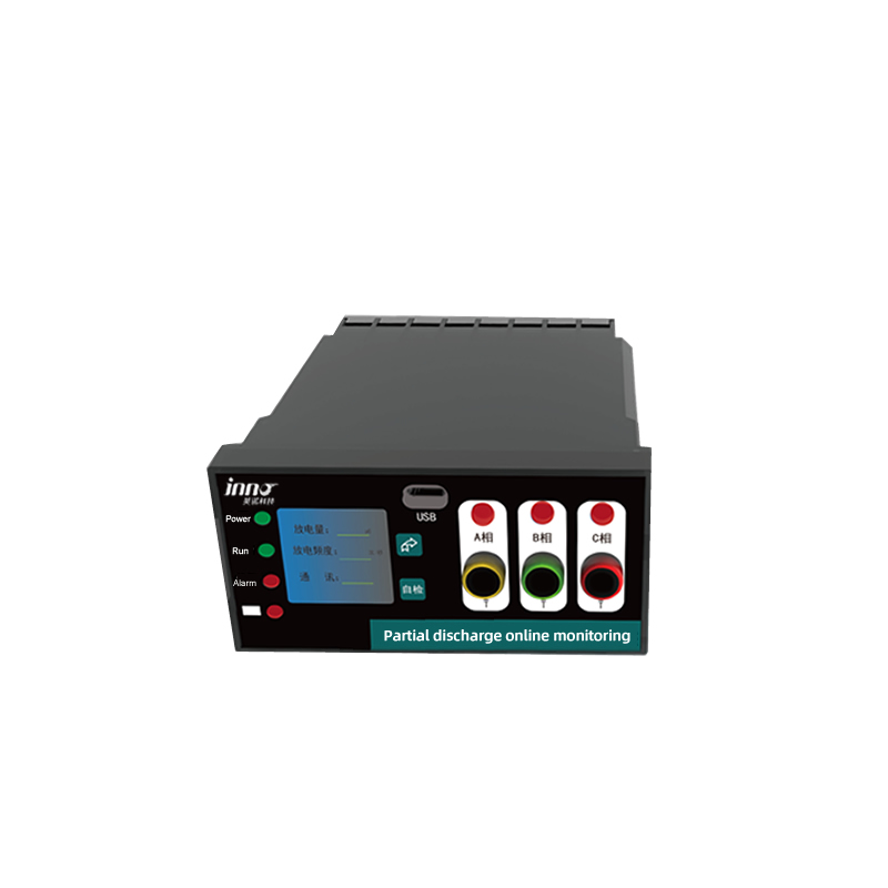
- UHF PD sensors detect ultra-high-frequency electromagnetic emissions caused by partial discharges inside transformers, switchgear, and other high-voltage equipment.
- They provide non-intrusive, real-time monitoring of insulation degradation, enabling early detection of faults and preventing catastrophic failures.
- UHF sensors operate typically between 300 MHz and 3 GHz, capturing PD signals immune to low-frequency interference and noise.
- These sensors are key components of digital transformer monitoring systems and predictive maintenance platforms.
- They comply with IEC 60270 and IEC 62478 standards, offering accurate, repeatable, and long-term PD detection performance.
Table of Contents
- 1. Overview — Why UHF PD Sensors Matter
- 2. What Are UHF PD Sensors
- 3. Working Principle of UHF Partial Discharge Detection
- 4. Types of UHF Sensors and Antenna Designs
- 5. Installation and Configuration in Transformers
- 6. Integration with Digital Monitoring Systems
- 7. Calibration, Sensitivity, and Data Processing
- 8. Use Cases in Power Transformers and GIS Systems
- 9. Global Application Examples
- 10. Advantages of UHF PD Monitoring
- 11. FAQ — UHF PD Sensors
- 12. About Our Manufacturing and Solutions
1. Overview — Why UHF PD Sensors Matter
Partial discharge (PD) is one of the earliest signs of insulation deterioration in high-voltage equipment. These micro-discharges, although tiny in energy, gradually erode insulation material and may lead to severe failures such as transformer breakdowns or switchgear explosions. Conventional PD detection systems based on electrical or acoustic signals often struggle in noisy substation environments. UHF PD sensors overcome this limitation by capturing electromagnetic radiation emitted during discharge events in the ultra-high-frequency range.
Unlike low-frequency detection methods, UHF sensors can identify PD signals even when the equipment is energized and under heavy load. They operate without physical contact with live conductors, making them completely safe and suitable for continuous online monitoring. By integrating UHF PD sensors with transformer digital monitoring systems or SCADA-based predictive software, operators gain round-the-clock visibility of insulation health.
The adoption of UHF detection technology has grown rapidly due to its robustness and accuracy. Today, most new transformers, gas-insulated switchgear (GIS), and high-voltage reactors include factory-installed UHF sensors as part of their standard design. This transition from manual inspections to automated, real-time monitoring represents a major milestone in power system reliability and asset management.
2. What Are UHF PD Sensors

UHF PD sensors are electromagnetic detectors designed to capture transient radio-frequency emissions produced by partial discharges in electrical insulation. These emissions are generated by rapid ionization and recombination processes that occur within air gaps, voids, or weak dielectric zones inside a transformer or GIS enclosure. Each PD pulse radiates an electromagnetic wave in the UHF band, typically between 300 MHz and 3 GHz. UHF sensors, equipped with precision antennas, receive these signals and convert them into electrical pulses for further analysis.
Most UHF PD sensors are built using metallic or ceramic housings that shield against environmental interference. They are designed for long-term stability under high temperature, high humidity, and strong electromagnetic fields. Some sensors feature built-in amplifiers or low-noise front ends to enhance weak signals and ensure accurate detection of PD activity even in large power transformers with thick metal enclosures.
Common deployment environments include:
- Power transformers (66 kV – 500 kV class) — monitoring winding and bushing discharges.
- Gas-insulated switchgear (GIS) — detecting PD in gas compartments and joints.
- Bus ducts and cable terminations — observing insulation degradation and corona activity.
- High-voltage reactors and capacitors — identifying internal or surface discharges.
The UHF sensor functions as a “radio eye” for insulation systems, capable of detecting electromagnetic energy that other sensor types cannot perceive. This makes it a fundamental part of transformer condition monitoring and predictive maintenance architectures.
3. Working Principle of UHF Partial Discharge Detection
The core working principle of UHF PD sensors lies in electromagnetic wave detection. When a partial discharge occurs within insulation, it releases a burst of energy that propagates through the surrounding dielectric medium as an electromagnetic wave. The pulse contains frequency components extending up to several gigahertz, depending on discharge geometry and propagation path. UHF sensors capture these pulses within their frequency response range and send the signal to a data acquisition unit for processing.
3.1 Electromagnetic Emission and Propagation
Each PD event acts like a miniature radio transmitter, generating a short electromagnetic pulse that travels through transformer oil, solid insulation, or air gaps. In transformers, the metallic tank acts as a resonant cavity, guiding and reflecting the waves until they reach the sensor antenna. In GIS systems, electromagnetic waves propagate along the metallic enclosure, often requiring directional or probe-type antennas for optimal coupling. The propagation characteristics depend on dielectric constant, geometry, and the presence of grounding or structural components.
3.2 Detection and Signal Conversion
UHF antennas—typically monopole, patch, or spiral types—convert the electromagnetic field into electrical voltage signals. These analog signals are amplified, filtered, and digitized by high-speed acquisition modules. Modern digital monitoring systems use fast sampling rates (up to several gigasamples per second) to accurately reconstruct the PD waveform. Advanced digital filters remove environmental noise, ensuring that only genuine PD activity is recorded. The result is a precise, time-correlated representation of discharge activity within the transformer insulation.
3.3 Time-of-Arrival and Source Localization
When multiple UHF sensors are installed at different locations on a transformer tank or GIS shell, the system can determine the time difference of arrival (TDOA) of PD pulses. Using triangulation algorithms, the software calculates the physical location of the discharge source with centimeter-level precision. This localization capability allows maintenance teams to identify defective windings, bushings, or joints without dismantling the equipment.
4. Types of UHF Sensors and Antenna Designs

Various UHF PD sensor designs exist to accommodate different installation environments, dielectric structures, and sensitivity requirements. The sensor’s design determines its frequency response, directionality, and installation feasibility. Below are the most common configurations used in transformer and GIS applications.
4.1 Internal UHF Sensors
Internal sensors are embedded during transformer or GIS manufacturing, typically mounted on inspection covers, oil flanges, or gas compartments. These sensors provide the highest detection sensitivity because they are located close to the PD source, minimizing signal attenuation through metallic shielding. Internal sensors are often sealed using high-dielectric glass or ceramic feedthroughs to maintain the integrity of the oil or gas enclosure. Their frequency response is carefully tuned to avoid resonance peaks and maintain linearity across the UHF band.
4.2 External Clamp-On UHF Sensors
External sensors are designed for retrofit applications where internal access is not available. These devices attach to transformer tank walls, cable terminations, or GIS joints using magnetic clamps or adhesive couplings. They detect radiated electromagnetic emissions through thin metallic surfaces or small apertures. Although slightly less sensitive than internal sensors, they offer the advantage of non-intrusive installation—no need to open the transformer tank or depressurize gas compartments. External sensors are widely used for field retrofits and mobile PD testing.
4.3 Directional and Broadband Antennas
Some advanced PD systems employ directional UHF antennas that focus on specific insulation zones or components. Spiral and log-periodic antenna types cover wide frequency ranges, ensuring detection of both low-energy corona and high-energy discharge pulses. Broadband sensors are used for general-purpose detection, while narrowband types target specific PD signatures for higher accuracy. Each antenna design involves trade-offs between sensitivity, frequency response, and mechanical robustness.
4.4 Patch and Probe Sensors for GIS Applications
In gas-insulated switchgear, space constraints and strong electromagnetic shielding require compact, high-sensitivity sensors. Patch antennas—flat metallic plates tuned to specific resonance frequencies—are commonly installed through monitoring ports or on enclosure flanges. Probe sensors with coaxial feedthroughs extend into the gas volume to enhance coupling efficiency. Both designs comply with GIS-specific safety and dielectric requirements, ensuring long-term stability under high voltage and gas pressure.
4.5 Custom Hybrid Sensors
Custom hybrid UHF sensors combine multiple detection modes, such as capacitive coupling and electromagnetic radiation sensing, to broaden detection coverage. They can be tailored for harsh environments, integrating temperature resistance, vibration endurance, and waterproofing. These hybrid units are often used in transformers exposed to extreme weather, marine installations, or high-altitude substations. Some also feature built-in signal conditioning electronics, allowing direct connection to digital monitoring systems.
5. Installation and Configuration in Transformers
Proper installation of UHF PD sensors is crucial for accurate detection and noise immunity. The placement strategy, grounding, and cabling methods significantly influence the system’s performance. Installation guidelines are generally based on IEC 62478 and utility-specific standards that define sensor positioning, sensitivity verification, and calibration methods.
5.1 Sensor Placement Strategy
In power transformers, sensors are typically mounted on the top, sides, and cable terminal areas of the tank to ensure full spatial coverage. For large three-phase transformers, at least three to six sensors are recommended. Each sensor covers a different detection zone, and overlapping regions improve fault localization accuracy. For retrofits, portable external sensors can be temporarily attached for diagnostic campaigns without draining oil or removing covers.
5.2 Cable Routing and Shielding
High-frequency signals are extremely sensitive to electromagnetic interference. Therefore, UHF sensors require low-loss coaxial cables with high shielding efficiency. Cable lengths are kept as short as possible to minimize attenuation, and all connections are properly grounded to prevent spurious coupling. When long cable runs are unavoidable, signal amplifiers or low-noise preamplifiers are installed near the sensor to maintain signal integrity.
5.3 Grounding and Reference Configuration
Each UHF PD system must establish a stable reference ground to avoid false readings. Improper grounding can lead to common-mode noise or coupling from external RF sources. The grounding network is usually connected directly to the transformer tank or GIS shell. Differential detection techniques—using two sensors as reference pairs—further enhance immunity to environmental interference. Grounding verification is part of the system commissioning checklist.
5.4 Safety and Isolation Considerations
Because transformers and GIS units operate at high voltage, UHF sensor installations must maintain electrical isolation. Feedthrough designs use dielectric materials to isolate sensor electrodes from live parts, ensuring no conductive path exists between the sensor and the energized components. Installation procedures follow strict electrical safety codes and are typically performed by trained technicians under de-energized conditions or using special live-line methods for external sensors.
5.5 Validation and Sensitivity Testing
Once installed, each sensor undergoes sensitivity validation. Artificial discharge sources—such as pulse generators or calibrators—simulate PD events to verify detection capability and signal path integrity. Test results establish baseline sensitivity levels that serve as reference for ongoing monitoring. This commissioning step ensures reliable performance throughout the equipment’s service life.
After successful setup, the UHF PD system becomes a continuous early-warning network within the transformer or GIS. Real-time data collection and analytics software continuously track insulation behavior, correlating PD intensity and repetition rates with load cycles, oil temperature, and aging indicators. Any deviation from normal discharge patterns immediately triggers alarms and alerts operators through the digital monitoring dashboard.
6. Integration with Digital Monitoring Systems
The true potential of UHF PD sensors is realized when they are integrated into a comprehensive digital transformer monitoring system. Such integration creates a unified platform that combines various sensor inputs, communication modules, and analytical algorithms to deliver a holistic view of the transformer’s operating condition. These advanced monitoring ecosystems go beyond detecting partial discharges—they continuously track thermal, electrical, mechanical, and environmental factors to predict future faults and optimize transformer performance.
6.1 Multi-Parameter Monitoring Architecture
A modern smart monitoring system for transformers typically includes the following modules and sensors working together:
- UHF PD Sensors: Detect electromagnetic emissions from partial discharges and insulation defects.
- Fiber Optic Temperature Sensors: Fluorescence-based fiber sensors directly measure the temperature of transformer windings and core hotspots with high accuracy and no electromagnetic interference.
- Vibration Sensors: Record mechanical oscillations and resonance patterns that indicate core looseness or abnormal magnetostriction.
- Bushing and Cable Joint Monitors: Measure leakage current and transient discharges at high-voltage terminations.
- Oil Dissolved Gas Analysis (DGA): Continuously analyze the concentration of gases like H₂, CO, and CH₄ to evaluate insulation degradation and internal faults.
- Moisture and Oil Quality Sensors: Detect water content, dielectric strength, and acidity of transformer oil to ensure insulation reliability.
- Acoustic Sensors: Monitor internal mechanical vibrations and structural resonance for fault localization (in conjunction with UHF PD results).
- Current and Voltage Transducers: Provide electrical load data, enabling correlation between PD activity and load conditions.
- Environmental Sensors: Measure ambient temperature, humidity, and noise for comprehensive situational awareness.
- Smoke and Arc Detection Sensors: Identify dangerous events such as oil vapor ignition or cable arcing inside the substation environment.
These sensors feed data into the central monitoring controller, which uses protocols like Modbus TCP/IP, IEC 61850, or RS-485 Modbus RTU for communication. The system transmits real-time data to a supervisory control and data acquisition (SCADA) platform or to cloud-based predictive analytics servers. Engineers can access dashboards remotely to visualize health indices, alarm trends, and detailed waveforms.
6.2 Smart Control and Local Interface
The integrated system often includes a local human-machine interface (HMI) that provides on-site display of transformer status. Operators can monitor parameters such as winding temperature, PD intensity, vibration level, humidity, and noise directly from a digital panel. Local logic controls automatically manage cooling fans, oil pumps, and dehumidifiers based on sensor feedback. For example, when temperature exceeds a threshold, the system triggers forced cooling; if humidity rises, the cabinet dehumidifier is activated. This automation ensures that optimal environmental conditions are maintained without manual intervention.
6.3 Communication and Data Synchronization
To maintain high accuracy, time synchronization between all sensors is achieved using GPS or IEEE 1588 precision time protocol (PTP). This ensures that partial discharge events, temperature changes, and current variations are correctly correlated in time. The synchronized data allows for advanced event correlation—linking PD pulses to voltage cycles, vibration peaks, or sudden temperature spikes. These relationships help engineers pinpoint root causes faster than traditional systems.
6.4 Predictive and Diagnostic Analytics
Predictive software within the monitoring system uses AI algorithms to detect hidden degradation patterns. For example, if a gradual increase in PD activity is accompanied by rising oil moisture and higher winding temperature, the software predicts insulation deterioration. Automated alerts and risk scores are then generated. By integrating all data streams—electrical, mechanical, and thermal—into one platform, the system provides comprehensive health diagnostics for the entire transformer lifecycle.
7. Calibration, Sensitivity, and Data Processing

Accurate calibration and data processing are fundamental to obtaining reliable results from UHF PD sensors. Since these sensors operate in the electromagnetic domain, their response characteristics must be verified against known standards. Calibration ensures that the amplitude and frequency response of each sensor match factory specifications and that cross-comparison between sensors remains consistent.
7.1 Sensitivity Verification
Before field installation, laboratory calibration using a PD calibration generator provides reference pulses across multiple frequency bands. The amplitude and timing of the received signals help establish each sensor’s detection threshold. During commissioning, artificial PD sources are used to verify on-site sensitivity under actual equipment conditions. Results are recorded to define baseline PD intensity levels.
7.2 Noise Rejection and Filtering
In real substations, electromagnetic interference (EMI) from switching operations, radio transmitters, or corona activity can mask genuine PD signals. Therefore, data acquisition units include advanced filtering algorithms such as adaptive notch filters and wavelet transforms. These algorithms isolate the true discharge signals based on pulse shape, frequency content, and time correlation. This ensures that PD measurements remain accurate even in electrically noisy environments.
7.3 Signal Analysis and Classification
Once signals are captured and filtered, the software performs pulse analysis to classify PD types—internal discharge, surface discharge, corona, or floating potential. Machine learning classifiers are increasingly used to automate this process. The system compares signal characteristics against large databases of known PD patterns, automatically identifying fault categories with high accuracy. Engineers can then take appropriate action depending on whether the issue is localized or systemic.
7.4 Trend and Statistical Monitoring
Trend analysis allows continuous tracking of PD activity over time. A sudden increase in PD count rate or energy level is a strong indicator of developing insulation faults. Statistical models such as Weibull or regression analysis predict failure probability based on historical data. These trends are displayed graphically on the monitoring dashboard, allowing users to schedule maintenance before catastrophic failure occurs.
8. Use Cases in Power Transformers and GIS Systems
UHF PD sensors have found extensive use in power systems worldwide, covering applications in transformers, GIS equipment, and even cable networks. Below are the key domains where UHF technology delivers measurable reliability improvements.
8.1 Power Transformers
In oil-immersed transformers, UHF sensors detect partial discharges originating from winding insulation, lead exits, tap changers, or core bolt structures. By correlating UHF data with fiber optic temperature readings and DGA analysis, engineers can accurately assess the aging rate of the insulation system. Early detection of PD activity allows targeted maintenance—such as oil purification, insulation reinforcement, or bushing replacement—without unplanned outages.
8.2 Gas-Insulated Switchgear (GIS)
For GIS installations, UHF PD sensors are often built into gas compartments or installed externally through dielectric windows. They continuously monitor for PD signals generated by particle contamination, spacer defects, or deteriorating contacts. The data is sent to the centralized monitoring unit, where algorithms differentiate between normal corona and critical internal discharges. This prevents catastrophic failures and reduces gas leakage risk, ensuring equipment longevity.
8.3 High-Voltage Cable Terminations
Cable joints and terminations are particularly prone to PD activity due to stress concentration and imperfect insulation interfaces. Portable UHF sensors or clamp-type antennas can be deployed during maintenance inspections to evaluate discharge activity. These sensors detect early degradation in accessories that might otherwise go unnoticed until failure occurs.
8.4 Substation Automation and SCADA Integration
In modern digital substations, UHF PD sensors connect directly to the SCADA system through fiber optic communication. The integration allows central operators to monitor PD alarms in real-time, alongside other transformer parameters such as temperature, vibration, and current load. This unified approach supports asset-level decision-making, reduces maintenance costs, and improves grid reliability.
8.5 Industrial and Renewable Energy Applications
Beyond traditional substations, UHF PD monitoring is now applied in wind turbine step-up transformers, solar inverter stations, and offshore platforms. These remote and unmanned installations benefit from continuous, autonomous monitoring. When combined with predictive software, the UHF system can automatically report potential insulation failures to central control rooms hundreds of kilometers away.
9. Global Application Examples
The practical implementation of UHF PD monitoring has been widely demonstrated in developed power systems around the world. A few representative examples highlight how this technology contributes to reliability and efficiency:
- Germany: Major utilities have integrated UHF PD sensors into their 400 kV transformers. By combining PD, DGA, and temperature data, they reduced transformer failure rates by over 30% within three years.
- Japan: High-speed rail substations employ compact UHF PD sensors for GIS monitoring, ensuring continuous reliability in dense urban environments with minimal service interruption.
- United States: Large utility companies in Texas and California use UHF sensors with fiber optic networks and cloud analytics to predict insulation faults weeks before they occur, reducing unplanned downtime significantly.
- United Kingdom: Offshore wind farms deploy hybrid UHF and vibration monitoring systems to track PD in remote transformers. Data is transmitted to centralized dashboards for condition-based maintenance scheduling.
- South Korea: Smart factories use UHF PD sensors integrated into IoT networks for transformer and busbar systems, helping optimize power reliability in automated production lines.
These global deployments prove the maturity and adaptability of UHF PD sensing technology. Regardless of climate, voltage class, or installation environment, this approach consistently delivers early fault detection, enabling data-driven maintenance decisions.
10. Advantages of UHF PD Monitoring
The implementation of UHF PD monitoring systems brings a fundamental transformation to transformer maintenance and asset management. Instead of relying on periodic inspections or reactive fault analysis, operators now gain the ability to continuously monitor, predict, and prevent failures before they impact service reliability. Below are the primary advantages in both technical and operational aspects.
10.1 Early Detection and Fault Prevention
UHF PD sensors detect discharge activity at its earliest stage—long before visible damage or abnormal heating occurs. Because electromagnetic emissions travel almost instantly through the equipment, the system provides real-time alerts within milliseconds of fault inception. This capability drastically reduces the probability of sudden transformer failure and allows planned maintenance rather than emergency shutdowns.
10.2 Non-Intrusive and Safe Operation
Unlike conventional electrical PD measurements that require direct access to live conductors, UHF sensors detect discharges through metal enclosures or dielectric windows. This makes the technology inherently safer, enabling continuous operation without disturbing equipment. Maintenance personnel can install, inspect, or replace sensors while the transformer remains energized under normal conditions.
10.3 Comprehensive Condition Awareness
When combined with other digital monitoring modules—such as fiber optic temperature monitoring, DGA analysis, moisture detection, vibration analysis, and environmental sensors—UHF PD monitoring forms part of a unified transformer health management ecosystem. Engineers can correlate multiple parameters to precisely understand the condition of insulation, cooling, and electrical systems. This multi-sensor synergy enhances diagnostic confidence and eliminates guesswork in fault interpretation.
10.4 Predictive Maintenance and Asset Optimization
By tracking PD activity trends and comparing them with load cycles and oil condition, the system’s analytics platform predicts remaining insulation life. Maintenance can then be scheduled only when necessary, optimizing cost and extending the service life of expensive assets. Predictive insights also guide asset managers on transformer replacement or refurbishment planning, improving capital utilization across large fleets.
10.5 Data Integration and Long-Term Reliability
Modern systems store all UHF PD data in secure databases that integrate with SCADA systems and cloud-based predictive analytics. This long-term data repository supports root cause investigations, forensic fault analysis, and continuous improvement of maintenance strategies. Historical trending allows engineers to detect even subtle degradation patterns over years of operation. Combined with machine learning algorithms, this forms the foundation of a truly intelligent power grid.
10.6 Regulatory Compliance and Standardization
UHF PD monitoring systems comply with international standards such as IEC 60270 for PD measurement, IEC 62478 for electromagnetic detection, and IEC 61850 for communication. These standards ensure interoperability and quality consistency across manufacturers and installations. For utilities operating globally distributed assets, adherence to standardized monitoring practices guarantees consistent data quality and safety performance.
10.7 Reduction in Maintenance Costs
Continuous PD monitoring reduces unplanned maintenance visits, eliminates the need for frequent manual inspections, and prevents costly equipment failures. Over time, this translates into substantial operational savings. Additionally, optimized maintenance scheduling minimizes service interruptions, increasing the availability and profitability of the electrical network.
11. FAQ — UHF PD Sensors
Q1: What exactly are UHF PD sensors used for?
UHF PD sensors are used to detect partial discharge activity inside high-voltage equipment such as transformers, GIS, and cable terminations. They capture ultra-high-frequency electromagnetic waves generated during discharge events. This information is analyzed to assess insulation condition, detect early-stage defects, and prevent failures. Essentially, UHF sensors act as the “ears” of the transformer’s insulation system, continuously listening for microscopic fault signals that electrical or acoustic methods might miss.
Q2: How do UHF PD sensors differ from conventional PD detection methods?
Traditional PD measurements (as per IEC 60270) use low-frequency current detection or acoustic signals. These methods can be affected by electrical noise or require equipment shutdown for testing. In contrast, UHF PD detection uses radio-frequency signals between 300 MHz and 3 GHz, which are immune to low-frequency interference. This enables online, non-intrusive, and highly sensitive monitoring even when the equipment is fully energized. The high bandwidth also allows for precise event timing, helping localize discharge sources accurately within the equipment.
Q3: Can UHF sensors be retrofitted to existing transformers or GIS?
Yes. There are two main installation methods: internal sensors integrated during manufacturing and external clamp-on sensors for retrofit applications. External sensors are non-invasive—they attach magnetically or via adhesive coupling to the tank or enclosure, requiring no oil draining or system shutdown. This flexibility makes UHF technology suitable for both new and existing assets, enabling modernization of legacy systems with minimal disruption.
Q4: How is the data from UHF PD sensors analyzed?
The raw signal captured by the UHF sensor is digitized using a high-speed acquisition system. Digital filters and algorithms remove background noise. The processed data is then evaluated for discharge pulse amplitude, repetition rate, phase correlation, and frequency spectrum. Using these characteristics, software platforms classify PD types (internal, surface, corona, or floating potential). When integrated with other data sources like temperature or oil quality, the software creates a comprehensive transformer health index that updates in real time.
Q5: What are the environmental limits for UHF PD sensors?
Most sensors are designed to operate in harsh conditions, including wide temperature ranges (-40°C to +85°C), high humidity, and strong electromagnetic fields. They are enclosed in stainless steel or aluminum housings with IP65–IP68 protection ratings. For GIS or outdoor substations, specialized dielectric feedthroughs ensure full gas or oil sealing, maintaining pressure integrity. Long-term field tests show stable performance over decades of operation, even under severe climatic conditions such as high altitude or coastal corrosion environments.
Q6: How are UHF sensors calibrated?
Calibration is typically performed using PD calibrators that generate reference pulses at known amplitudes and frequencies. The sensor’s frequency response and sensitivity are verified against these standards. During field installation, calibration checks are conducted with portable pulse generators to confirm correct operation. The calibration data is stored in the monitoring system for traceability and compliance audits.
Q7: What other parameters should be monitored together with PD?
For a comprehensive understanding of transformer health, PD monitoring should be complemented by several other measurements:
- Winding and Core Temperature: Measured via fluorescence-based fiber optic sensors to detect overload and hot-spot conditions.
- Oil Dissolved Gas Analysis (DGA): Indicates chemical aging and fault types inside the insulation system.
- Vibration and Noise: Reveal mechanical looseness, resonance, or abnormal magnetic forces.
- Moisture and Humidity: Affect dielectric strength and accelerate insulation degradation.
- Load Current and Voltage: Provide electrical stress data for correlating with PD activity.
- Smoke or Arc Sensors: Detect extreme events that follow prolonged PD activity.
Integrating these parameters into a unified system ensures that operators not only detect PD but also understand its cause, severity, and potential impact.
Q8: Can UHF PD sensors be integrated into smart grids and IoT systems?
Absolutely. UHF PD sensors can connect via Ethernet, fiber optics, or wireless modules to smart grid platforms. Data from multiple substations can be transmitted to centralized servers for AI-based analysis and decision-making. Through IoT integration, maintenance teams receive instant alerts via mobile devices or control dashboards. This makes UHF PD technology a key enabler of digital substations and predictive maintenance strategies in modern power grids.
Q9: What standards govern the design and operation of UHF PD systems?
International standards such as IEC 60270 define PD measurement fundamentals, while IEC 62478 focuses on electromagnetic detection in the UHF range. IEC 61850 specifies communication and interoperability requirements for integration with digital substations. Compliance with these standards ensures reliable performance, accurate measurements, and compatibility with existing monitoring systems.
Q10: What is the return on investment (ROI) of installing UHF PD monitoring?
The ROI is typically realized within 1–3 years due to avoided failures, reduced maintenance costs, and improved asset uptime. Preventing a single major transformer failure can save hundreds of thousands of dollars in repair and outage costs. Additionally, predictive analytics from UHF systems help extend transformer lifespan, optimize spare parts inventory, and enhance operational planning, further improving long-term financial performance.
12. About Our Manufacturing and Solutions
We are a professional manufacturer specializing in transformer monitoring systems and UHF PD sensor solutions. Our products are designed, assembled, and tested in compliance with international standards including IEC, ISO 9001, and CE. With in-house R&D, we offer a wide portfolio of diagnostic and monitoring devices covering:
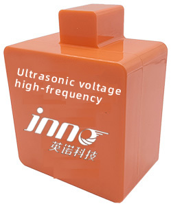
- UHF partial discharge detection antennas and acquisition modules
- Fluorescence-based fiber optic temperature sensors for winding and core monitoring
- Online DGA analyzers and oil moisture monitors
- Vibration, arc, smoke, and acoustic sensors
- Digital transformer monitoring units with Modbus TCP/IP, RS485, and IEC 61850 protocols
Our systems are installed in power utilities, industrial substations, and renewable energy networks across Asia, Europe, and South America. We provide customized solutions for different transformer capacities and environmental conditions, ensuring precise fit and reliable long-term operation. Clients can request detailed product specifications, test reports, and calibration certificates directly from our engineering team.
For inquiries, technical support, or quotation requests, please contact us through the website’s consultation form. Our specialists will assist you in selecting the right UHF PD monitoring system and integrating it into your existing transformer network.
We are a certified factory manufacturer providing not only high-quality sensors but complete transformer diagnostic solutions. All devices undergo rigorous quality control, accelerated aging tests, and EMC verification. Whether you are a power utility, OEM, or engineering contractor, we offer end-to-end solutions—from design to installation and after-sales calibration support.
By choosing our UHF PD systems, you gain access to predictive analytics, real-time insights, and proven safety performance—a critical step toward smarter, more reliable power infrastructure.

Fiber optic temperature sensor, Intelligent monitoring system, Distributed fiber optic manufacturer in China
 |
 |
 |