 INNO fibre optic temperature sensors ,temperature monitoring systems.
- Real-time transformer health monitoring provides continuous visibility of electrical, thermal, and mechanical conditions.
- Integrated sensors—such as DGA, UHF partial discharge, and fiber optic temperature—enable early fault detection and predictive maintenance.
- Smart IoT gateways connect transformers to SCADA and cloud systems for analytics and automated protection.
- In tropical regions like Vietnam and Indonesia, climate-adaptive thresholds improve reliability under high humidity and temperature.
- Factory-built systems with certified sensors ensure long-term stability, accuracy, and cybersecurity compliance.
Table of Contents
- 1. What Is a Real-Time Transformer Health Monitoring System
- 2. Why Transformer Health Monitoring Is Important
- 3. Transformer Components and Structure Overview
- 4. Transformer Fault Types and Failure Causes
- 5. How Does Transformer Monitoring Work
- 6. Core Components of the Monitoring System
- 7. Key Sensors and Measured Parameters
- 8. Fiber Optic Temperature Monitoring for Transformer Windings
- 9. Dissolved Gas Analysis (DGA) and Oil Quality Monitoring
- 10. Partial Discharge (UHF) Detection and Insulation Faults
- 11. Mechanical and Environmental Condition Monitoring
- 12. Transformer Alert and Protection Functions
- 13. Communication and SCADA Integration
- 14. Predictive Maintenance and AI Data Analytics
- 15. Smart Transformer Monitoring in IoT Systems
- 16. Types of Monitoring Systems (Online, Portable, Integrated)
- 17. Transformer Case Studies in Vietnam and Indonesia
- 18. Installation and Setup Guidelines
- 19. Frequently Asked Questions (Extended Technical FAQ)
- 20. About Our Factory and Technical Solutions
1. What Is a Real-Time Transformer Health Monitoring System
A real-time transformer health monitoring system is an integrated hardware–software platform that continuously observes a transformer’s condition while it remains in service. It acquires raw data from embedded and external sensors, processes the signals at the edge, synchronizes timestamps across channels, and streams cleaned data to control rooms or cloud analytics. The system computes health indices, predicts risk, and issues alerts whenever operating limits are exceeded or abnormal trends emerge.
Unlike periodic inspections, real-time monitoring does not wait for symptoms to become visible. It detects the precursors—subtle rises in winding hot-spot temperature, early gas formation, sporadic partial discharge bursts, or small shifts in vibration signatures—that precede failures. In coastal or equatorial climates typical of Ho Chi Minh City, Da Nang, Jakarta, and Surabaya, continuous surveillance is essential because humidity and heat accelerate insulation aging and oil degradation.
Key outcomes include better situational awareness for grid operators, fewer emergency shutdowns for industrial users, and a strong value proposition for transformer OEMs and agents who supply “smart-ready” equipment into Southeast Asian projects.
![]()
2. Why Transformer Health Monitoring Is Important
Transformers are high-value, mission-critical assets with slow failure progression but severe consequence when breakdown occurs. Health monitoring addresses three realities of field operation:
- Thermal stress is cumulative: Each hour at elevated temperature shortens insulation life. Real-time hot-spot tracking enables proactive cooling control and load management.
- Chemical aging is silent: Oxidation, moisture ingress, and cellulose depolymerization progress without obvious signs. Online oil and moisture monitoring reveals the chemistry in motion.
- Electrical defects start small: Minor partial discharge, loose connections, and surface tracking can persist for months before a flashover. UHF detection and event trending expose these early-stage defects.
For Vietnam and Indonesia, monitoring mitigates specific regional risks: frequent lightning impulses, saline air in coastal areas, and thermal loading due to high ambient temperatures. It supports manufacturing hubs—textiles, electronics, cement, and petrochemicals—where unplanned power loss leads to disproportionate production and contractual penalties.
3. Transformer Components and Structure Overview
To monitor effectively, the system must “understand” the transformer’s physical layout and which parts are most sensitive. The table maps key components to their function and typical monitoring focus.
| Component | Function | Monitoring Focus | Typical Sensors |
|---|---|---|---|
| Core | Provides magnetic path; minimizes core loss | Heating, vibration, core bolt insulation | Temperature probes, accelerometers |
| LV/HV Windings | Carry current; induce voltage | Hot-spot temperature, inter-turn faults | Fluorescent fiber optic, RTD, current transducers |
| Tap Changer (OLTC) | Voltage regulation under load | Contact wear, arcing, oil condition | Temperature, current signature, DGA (C2H2, C2H4) |
| Bushings | High-voltage terminals/insulators | Dielectric loss, surface tracking, PD | UHF PD, leakage current, capacitance/tan δ |
| Oil–Paper Insulation | Electrical insulation & cooling medium | Moisture, acidity, dissolved gases | Online DGA, moisture-in-oil sensors |
| Cooling System | Removes losses (ONAN/ONAF/OFAF/ODAF) | Fan/pump status, radiator efficiency | Temperature, flow, power relays |
| Conservator & Breather | Oil volume compensation; drying | Oil level, silica gel saturation | Level switches, humidity |
| Tank & Accessories | Mechanical enclosure; fittings | Pressure, leaks, PRD activation | Pressure, tilt, leakage detectors |
This structural view guides sensor placement and alert strategy. For example, fiber optic probes are routed to winding hot-spots; UHF antennas are positioned near bushings and cable terminations; moisture probes sit in oil lines with representative circulation.
4. Transformer Fault Types and Failure Causes
Failures rarely arise from a single cause; they are typically multi-factor effects. The matrix below summarizes common fault types, root causes, early indicators, and recommended monitoring signals.
| Fault Type | Root Causes | Early Indicators | Best Monitoring Signals |
|---|---|---|---|
| Thermal Overload | High load, blocked radiators, fan failure | Rising hot-spot; top-oil surge | Fiber optic hot-spot, top-oil, load current |
| Insulation Aging | High temperature, moisture, oxidation | Moisture-in-oil increase; PD onset | Moisture sensors, DGA (CO, CO2), UHF PD |
| Inter-Turn Fault | Mechanical shock, dielectric weakness | Localized heating; differential current drift | Hot-spot gradient, current imbalance |
| OLTC Arcing | Contact wear, misalignment, low oil quality | Acetylene spikes; temperature spikes at operations | DGA (C2H2), temperature near OLTC, operation counter |
| Bushing Breakdown | Contamination, aging, moisture ingress | Surface tracking; PD near terminals | UHF PD near bushings, leakage current/tan δ |
| Core Hot-Spot | Shorted laminations, flux imbalance | Vibration shift; localized temperature rise | Accelerometers, core temperature probes |
| Oil Degradation | Oxidation, contamination, aeration | Acidity rise; moisture; PD activity | Oil QA (acid number), moisture, DGA |
| External Flashover | Pollution, salt spray, lightning | Corona noise; surface discharge | UHF PD, weather/ambient sensors |
Field experience in Vietnam and Indonesia shows that moisture-related and OLTC-related issues are disproportionately represented due to climate and frequent tap operations for voltage stability. A robust monitoring program prioritizes those channels without ignoring the rest.
5. How Does Transformer Monitoring Work
The workflow combines synchronized data collection with contextual analytics. A concise, operator-friendly sequence is:
- Acquire: Sensors stream measurements (temperature, gases, PD, vibration, current, humidity) at defined sampling rates. GPS/PTP time-sync ensures cross-channel alignment.
- Qualify: Edge firmware filters noise, checks plausibility (range, rate-of-change), and tags quality flags (OK, suspect, invalid).
- Aggregate: The data acquisition unit merges channels into time-aligned frames and computes first-order features (rolling averages, peaks, harmonic content, PD counts).
- Analyze: Health indices and risk scores are derived from models that consider thermal aging, gas ratios, PD severity, and loading history.
- Alert & Act: Thresholds and expert rules drive warnings, alarms, and automated controls (fan/pump start, OLTC arcing protection). Events propagate to HMI, SCADA, and cloud dashboards.
This closed loop transforms raw signals into operational decisions. For a manufacturing campus in Bình Dương or East Java, the same platform scales across dozens of transformers, standardizing health KPIs and alert semantics.
6. Core Components of the Monitoring System
While configurations vary, the most successful deployments in Southeast Asia share a common architecture that balances robustness, interoperability, and serviceability.
6.1 Edge Hardware
- Data Acquisition Unit (DAU): Multi-channel analog/digital inputs, high-speed sampling for UHF PD, isolated inputs for 4–20 mA/0–10 V, and digital counters for OLTC operations.
- Industrial Controller: Real-time OS, deterministic I/O, local rules engine for alarm escalation and control actions.
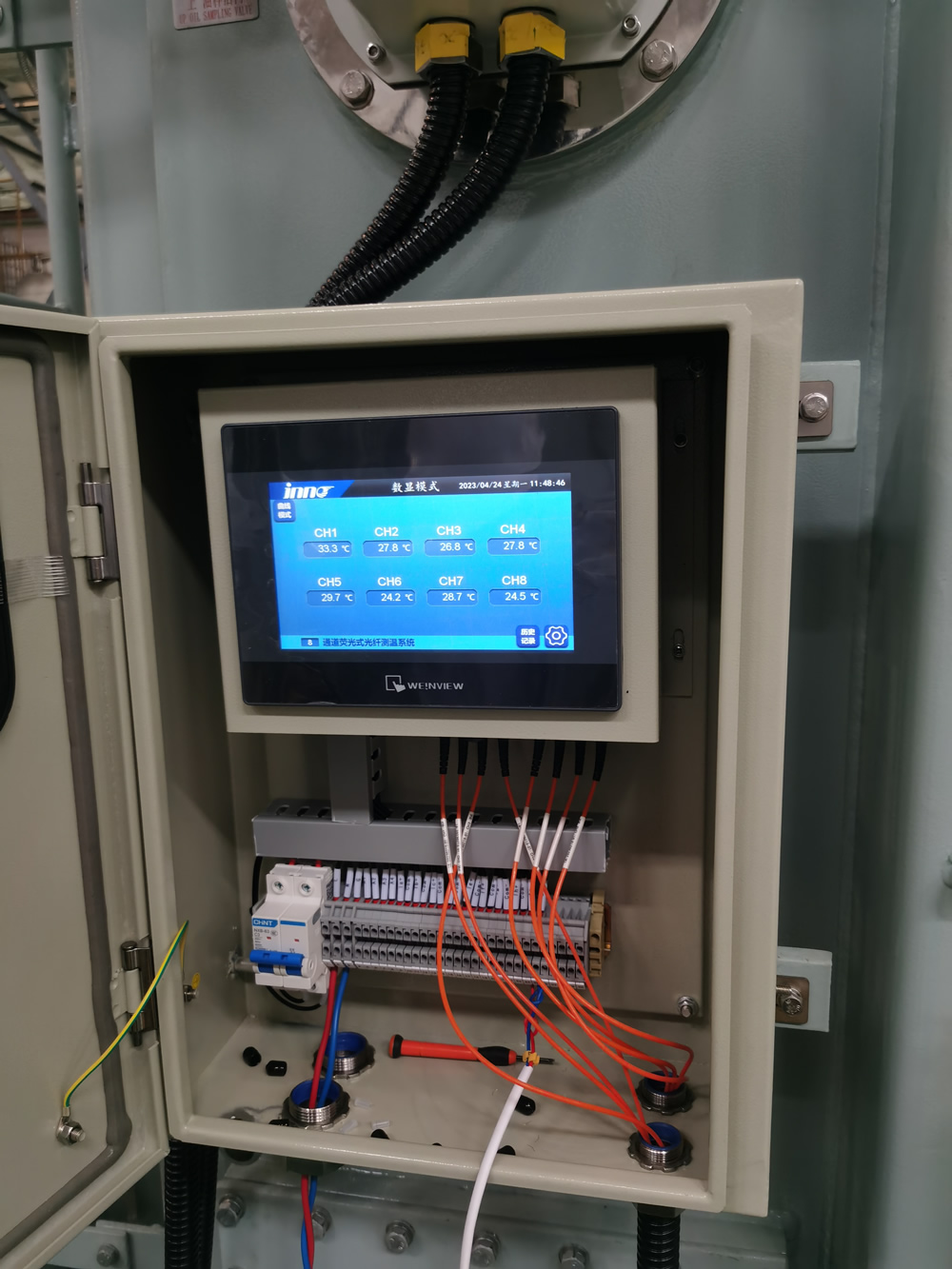
- Local HMI: 7–15 inch touchscreen for on-site status, trends, and manual overrides; multilingual UI (English, Vietnamese, Bahasa Indonesia).
6.2 Communications
- Fieldbus: RS-485 Modbus RTU for rugged legacy integration; CAN for local peripheral networks.
- Ethernet: Modbus TCP/IP and OPC UA to DCS/SCADA; VLAN segmentation for security.
- Substation Protocols: IEC 61850 MMS/GOOSE for event speed and interoperability.
- Backhaul: Fiber, 4G/5G, or microwave links to control centers and cloud.
6.3 Software Stack
- Edge Analytics: Feature extraction, rule-based alarms, buffering for intermittent connectivity.
- SCADA Integration: Tag mapping, historian logging, enterprise user management, audit trails.
- Cloud Analytics: Fleet-wide dashboards, predictive models, and API endpoints for ERP/EAM systems.
6.4 Power and Protection
- Power Supplies: AC 220 V in; DC 24 V/12 V protected outputs for sensors; surge protection tuned for lightning-prone regions.
- Enclosures: IP65/66 for outdoor yards; stainless options for coastal salt exposure.
7. Key Sensors and Measured Parameters
The system’s value depends on the fidelity and complementarity of its sensors. Selecting the right mix is essential for tropical deployment and for the asset’s voltage class and duty cycle.

7.1 Sensor–Parameter Matrix
| Parameter | Primary Sensor | Operating Principle | Why It Matters |
|---|---|---|---|
| Winding Hot-Spot | Fluorescent Fiber Optic | Fluorescence decay time vs. temperature | Direct, EMI-immune hot-spot captures thermal aging drivers |
| Top-Oil / Bottom-Oil | RTD / Thermistor | Resistive temperature variation | Cooling efficiency; thermal gradient evaluation |
| Dissolved Gases | Online DGA Sensor | Optical/electrochemical dissolved gas quantification | Identifies arcing, overheating, insulation decomposition |
| Moisture-in-Oil | Capacitive/Optical Moisture Probe | Dielectric/absorption shift with water content | Dielectric strength, paper aging, PD propensity |
| Partial Discharge | UHF Antenna Sensor | Electromagnetic emission 300 MHz–3 GHz | Early insulation defect detection; localization with TDOA |
| Vibration | Accelerometer | Piezoelectric response to motion | Core looseness, OLTC anomalies, fan imbalance |
| Load Current/Voltage | CT/VT, Rogowski, Hall Sensors | Electromagnetic induction/Hall effect | Thermal stress correlation; harmonic analysis |
| Ambient RH/Temp | Digital Hygro-Thermal | Capacitive humidity, bandgap temp | Climate context for derating and alarm tuning |
| Oil Level/Pressure | Float/Capacitive; Pressure Transducer | Displacement/diaphragm deformation | Leak detection; PRD conditions |
| Smoke/Arc Light | Optical/UV Sensor | Scattered light/UV emission | Immediate hazard detection and trip logic |
7.2 Data Quality and Placement
- Placement matters: Windings require embedded fiber routes; UHF antennas near bushings and cable heads; moisture probes in circulating oil lines; accelerometers on core clamps.
- Calibration and drift: Factory calibration plus annual verification; DGA cross-checked with lab samples; fiber optic sensors feature inherently stable references.
- Synchronization: GPS/PTP time alignment is essential for PD triangulation and cause–effect studies (e.g., load impulses vs. temperature spikes).
7.3 Multi-Sensor Fusion
A single parameter rarely tells the whole story. The strongest diagnosis comes from correlating channels:
- Hot-spot ↑ + DGA (C2H2) ↑ → probable arcing at OLTC or winding leads.
- Moisture ↑ + PD bursts → surface tracking risk on paper–oil interfaces.
- Vibration shift + fan current ↑ → cooling fan bearing wear or imbalance.
- Harmonics ↑ + temperature ↑ → non-linear loads driving extra copper losses.
For OEMs and agents in Vietnam and Indonesia: we provide sensor layout templates for 10–220 kV classes, tailored for marine/coastal exposure and high-humidity substations, plus localized documentation for commissioning teams.
8. Fiber Optic Temperature Monitoring for Transformer Windings
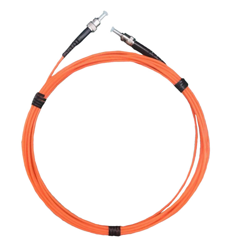
Fiber optic temperature monitoring delivers direct, high-precision hot-spot readings inside transformer windings and core packs. Fluorescence decay thermometry is immune to electromagnetic interference, making it ideal for high-current, high-field areas where electrical sensors struggle. Real-time hot-spot visibility enables accurate thermal aging models, dynamic loading strategies, and automated fan/pump control, which are crucial for networks in hot, humid regions across Vietnam and Indonesia.
8.1 Why Fiber Optics for Hot-Spot Sensing
- Direct contact with hot-spot: Probes are embedded during manufacturing or installed along cooling ducts to track the most thermally stressed conductors.
- EMI immunity: Optical interrogation avoids induction noise and RF pickup near busbars and OLTC chambers.
- Fast response: Millisecond-level acquisition captures rapid temperature excursions during step load changes or faults.
- Stability in oil: Fluorescent probes are designed for long-term stability in mineral and ester oils.
8.2 Typical Deployment and Multipoint Layout
Large power transformers commonly use 3–12 probes across phases and winding sections. Placement prioritizes hot ducts, upper radial spacers, and areas near lead exits. For integrated systems, the fiber interrogator connects to the same DAU used for DGA, UHF PD, and vibration, unifying timestamps and alarm logic.
| Location | Objective | Notes |
|---|---|---|
| HV Winding Inner/Outer | Track highest copper losses and eddy hotspots | Use multiple probes for axial gradient profiling |
| LV Winding Hot Duct | Capture thermal bottlenecks during high load | Ideal for dynamic fan control schemes |
| Core Clamp Region | Identify localized core heating | Correlate with vibration changes |
8.3 Control Actions from Hot-Spot Data
- Adaptive cooling: Start/stop fans per hot-spot thresholds rather than top-oil alone.
- Load management: Derate or redistribute feeders when hot-spot exceeds allowable limits.
- Aging estimation: Real-time calculation of insulation loss-of-life for asset planning.
Implementation note for OEMs in Bac Ninh and Surabaya: provide factory-installed fiber routing guides and acceptance test templates. Our platform supports per-probe alarm bands and IEC-based thermal models for life consumption.
9. Dissolved Gas Analysis (DGA) and Oil Quality Monitoring

Dissolved Gas Analysis detects chemical fingerprints of faults by measuring gases such as H2, CO, CO2, CH4, C2H2, C2H4, and C2H6. Online DGA sensors provide continuous tracking, while periodic lab tests validate calibration and assess broader oil health metrics (acidity, interfacial tension, furans). In tropical grids, moisture rise and oxidation can accelerate gas formation, so real-time observation is particularly valuable.
9.1 Interpreting Gas Signatures
- Hydrogen (H2): General fault indicator; early PD or overheating.
- Acetylene (C2H2): Strong sign of arcing, often linked to OLTC or lead issues.
- Ethylene/Ethane (C2H4/C2H6): Thermal faults; correlates with hot-spot and load cycling.
- CO/CO2: Cellulose degradation; paper aging and moisture stress.
9.2 Oil Quality and Moisture
Oil acts as both dielectric and coolant. Quality metrics—acidity (TAN), dielectric breakdown voltage, interfacial tension—indicate oxidation and contamination. Moisture-in-oil directly lowers dielectric strength and promotes PD. Online moisture probes and periodic Karl Fischer lab results together provide reliable oversight.

| Oil Metric | Purpose | Monitoring Method |
|---|---|---|
| Dissolved Gases | Fault type identification | Online DGA + quarterly lab confirmation |
| Moisture (ppm) | Dielectric margin, paper aging | Online moisture probe + lab KF |
| Acidity (TAN) | Oxidation progression | Lab testing semi-annually |
| Breakdown Voltage | Insulation strength check | Lab BDV test |
9.3 DGA + Other Channels = Stronger Diagnosis
- DGA (C2H2) ↑ + UHF PD ↑: Combined evidence of arcing; inspect OLTC and leads.
- CO/CO2 ↑ + hot-spot ↑: Paper aging accelerating under thermal stress; review cooling.
- Moisture ↑ + PD bursts: Surface tracking risk; consider drying and sealing improvements.
Regional note: coastal installations in Da Nang and Makassar often show faster moisture ingress; our algorithms include climate-aware thresholding to reduce nuisance alarms.
10. Partial Discharge (UHF) Detection and Insulation Faults

UHF PD monitoring captures electromagnetic emissions (300 MHz–3 GHz) from micro-discharges that precede insulation breakdown. It works under load without intrusive connections and resists low-frequency noise from switching and harmonics. In conjunction with time-of-arrival methods, multi-antenna arrays can localize PD sources to specific bushings, leads, or winding segments.
10.1 PD Phenomena and Patterns
- Internal PD: Voids in paper/epoxy; sporadic but energy accumulates.
- Surface PD: Tracking on insulation interfaces; sensitive to humidity.
- Corona: High-field tip effects; often lower energy but persistent.
10.2 PD Severity and Trending
Because PD varies with load, temperature, and humidity, trends matter more than snapshots. Our platform tracks pulse rate, magnitude, clustering, and phase relation, then correlates with hot-spot and moisture to assign severity levels.
| Indicator | Insight | Action |
|---|---|---|
| PD Count Rate ↑ | Growing discharge activity | Schedule inspection; verify humidity control |
| High-Magnitude Bursts | Possible arcing episodes | Immediate condition check; DGA validation |
| Phase-Correlated Pulses | Load-angle sensitive defect | Examine winding stress points/leads |
10.3 Practical Deployment in SEA
In Vietnam’s urban substations and Indonesia’s coastal plants, antennas are positioned near bushings, cable heads, and OLTC compartments. Shielded coax with short runs and robust grounding minimizes RF loss. Automatic noise classification excludes radio interference and corona from outdoor fittings when non-critical.

11. Mechanical and Environmental Condition Monitoring
Electrical health is inseparable from mechanical and environmental context. Vibration, acoustic, humidity, and ambient temperature channels provide the backdrop for interpreting electrical and chemical data.
11.1 Vibration and Acoustic
- Core clamp accelerometers: Detect loose laminations, magnetostriction shifts, and resonance.
- OLTC acoustic signature: Learn normal operation “fingerprints”; detect contact bounce or misalignment.
- Fan/pump condition: Characterize bearing wear via spectral analysis; cross-check against current draw.
11.2 Environmental Context
- Ambient RH/temperature: Humidity spikes raise PD susceptibility; high ambient reduces cooling margin.
- Enclosure conditions: Cabinet heaters and dehumidifiers keep electronics within rated limits.
- Salt spray/corrosion: Coastal stations require stainless enclosures and coated radiators.
11.3 Example Correlations
- Vibration ↑ + OLTC operation count ↑: Inspect tap changer contacts and diverter switch.
- Ambient temp ↑ + hot-spot ↑ without load change: Tune thermal alarm bands seasonally.
- Humidity ↑ + PD count ↑: Improve sealing; consider breather maintenance and drying cycle.
12. Transformer Alert and Protection Functions
The alert layer translates analytics into actions. Multi-level notifications and control outputs protect equipment and staff while minimizing nuisance trips.
12.1 Alarm Levels
- Advisory: Trend deviation; log event, notify via dashboard.
- Warning: Threshold exceeded; SMS/email to duty engineers; schedule inspection.
- Critical: Rapid escalation or multi-symptom fault; local siren/beacon; remote alarms to SCADA; initiate safe state.
12.2 Automated Actions
- Cooling control: Fan/pump start on hot-spot thresholds or rate-of-rise logic.
- Environmental control: Dehumidifier/heater activation for cabinets and RMUs.
- Interlocking: Trip commands routed through protection relays for arc/smoke events.
| Trigger | Logic | Action |
|---|---|---|
| Hot-spot ≥ setpoint | Hysteresis + min-on time | Start fans; notify operator |
| DGA acetylene spike | Delta vs. baseline + PD corroboration | Critical alarm; OLTC inspection ticket |
| Smoke/arc detected | Immediate, non-latching | Trip interlock; site evacuation alarm |
Service note for agents in Hanoi and Bandung: our controller exposes both dry contact and high-current relay outputs (AC 220 V/10 A) for direct control wiring, plus event acknowledgments to SCADA.
13. Communication and SCADA Integration
Interoperability determines operational value. The platform supports station standards and cloud pathways to ensure data reaches decision-makers securely and promptly.
13.1 Protocols and Data Models
- IEC 61850: MMS for supervisory data; GOOSE for events; SCL for data model portability.
- Modbus TCP/RTU: Fast, simple mapping for PLC/DCS environments.
- OPC UA: Vendor-neutral integration across enterprise layers.
- MQTT: Lightweight publish/subscribe for IoT backhaul over 4G/5G.
13.2 Time Synchronization and Historian
Accurate correlation hinges on time. GPS or IEEE 1588 PTP aligns edge devices; historian archives include tags for quality flags, versioning, and calibration references. Event replay tools let engineers reconstruct pre-fault conditions.
13.3 Cybersecurity
- Segmentation: Separate OT/IT VLANs and firewalled conduits; least-privilege access.
- Encryption & auth: TLS for remote access; role-based accounts and audit logs.
- Update policy: Digitally signed firmware; scheduled patch windows; rollback images onsite.
13.4 Control Room Views
- Single-line overlay: Health badges on each transformer and feeder.
- Alarm wall: Severity-based tiles with color coding and acknowledge/escalate workflow.
- Trend workbench: Multi-signal overlays (hot-spot, DGA, PD, load) with correlation cursors.
14. Predictive Maintenance and AI Data Analytics
Predictive analytics converts streams into foresight. Statistical models, physics-informed digital twins, and machine learning work together to forecast risk and remaining useful life (RUL).
14.1 Model Types
- Thermal aging models: Arrhenius-based life consumption from hot-spot histories.
- Gas ratio diagnostics: Rule-based and data-driven hybrids to refine fault classification.
- PD trend classifiers: Clustering and anomaly detection on pulse features and phase patterns.
- Mechanical analytics: Spectral fingerprints for fans/pumps and OLTC acoustics.
14.2 Data Fusion
AI layers combine independent channels into a consolidated Transformer Health Index (THI). Confidence scoring accounts for sensor quality, operating mode (load, ambient), and recent maintenance. The THI supports fleet ranking, work order prioritization, and outage risk simulations.
14.3 From Insight to Action
- Detect: Classifier flags deviation (e.g., PD cluster growth).
- Diagnose: Cross-check with DGA and hot-spot to pinpoint likely cause.
- Decide: Recommend inspection, oil processing, or load curtailment.
- Dispatch: Auto-create work orders with parts list and safety steps.
14.4 Southeast Asia–Specific Considerations
- Monsoon season adaptation: Dynamic thresholds for humidity/ambient temperature shifts.
- Lightning density maps: Overlay impulse events to contextualize PD spikes.
- Coastal corrosion indices: Weight enclosure and radiator condition in THI.
Engagement note: request our demo workspace to visualize THI, PD trend overlays, and climate-adaptive thresholds tailored for Vietnamese and Indonesian sites.
15. Smart Transformer Monitoring in IoT Systems
IoT-native architectures extend real-time transformer monitoring beyond the substation fence, enabling secure data sharing, remote diagnostics, and fleetwide optimization. A layered design separates field acquisition, edge analytics, and cloud applications to balance latency, bandwidth, and cybersecurity.
15.1 IoT Reference Architecture
- Field Layer: Sensors, DAUs, and controllers at the transformer; deterministic sampling, local alarms, and buffering.
- Edge Layer: Gateway with protocol translation (IEC 61850, Modbus, OPC UA), data quality checks, TLS tunnels, and store-and-forward.
- Cloud Layer: Time-series database, analytics engine, model registry, dashboards, and role-based access for multi-site users.
15.2 Connectivity Options
| Backhaul | Strengths | Considerations |
|---|---|---|
| Fiber | High bandwidth, low latency | CAPEX for trenching; ideal for campuses and utilities |
| 4G/5G | Quick deployment; rural reach | Carrier SLAs; VPN/APN for OT isolation |
| Microwave | Point-to-point for remote yards | Line-of-sight planning; weather effects |
15.3 Cloud Applications
- Fleet Health Index: Compare THI across assets and prioritize interventions.
- Anomaly Feeds: Stream PD bursts, DGA spikes, and hot-spot excursions to an incident wall.
- Model Lifecycle: Track versioned ML models, drift metrics, and re-training schedules.
15.4 Operational Use Cases
- Remote Expert Assist: Engineers in Hanoi or Jakarta guide site teams via live dashboards and embedded procedures.
- OEM Warranty Analytics: Evidence-based decisions using operating histories and alarm root causes.
- Contracted Monitoring: Service providers deliver 24/7 oversight for industrial parks and IPPs.
16. Types of Monitoring Systems (Online, Portable, Integrated)
Selection depends on risk profile, asset criticality, and budget. Systems often coexist within the same fleet.
16.1 Online Continuous Monitoring
- Scope: Hot-spot fiber optics, DGA, moisture, UHF PD, vibration, load, ambient.
- Best for: GSU units, 110–220 kV substations, critical industrial feeders.
- Strength: Real-time risk mitigation and automated response.
16.2 Portable and Semi-Online
- Scope: Periodic PD scans, handheld DGA sampling, thermal imaging.
- Best for: Smaller distribution units and budget-limited sites.
- Strength: Lower cost; complements continuous systems.
16.3 Integrated Smart Transformers (Factory-Fitted)
- Scope: OEM-installed probes, interrogators, gateways, and enclosure kits.
- Best for: New builds and expansions seeking plug-and-play digitalization.
- Strength: Simplified commissioning, optimized sensor placement, and warranty alignment.
16.4 Hybrid Strategy
Many utilities adopt a hybrid approach: online systems for top-critical assets, portable diagnostics for the remainder, and progressive retrofits aligned with maintenance windows.
17. Transformer Case Studies in Vietnam and Indonesia
These cases illustrate climate-aware monitoring, rapid alerting, and predictive decisions that prevented outages and optimized maintenance.
17.1 Vietnam — Industrial Park 110 kV Substation
- Challenge: Frequent humidity spikes and high load growth causing hot-spot excursions.
- Solution: Online fiber hot-spot, DGA, moisture-in-oil, UHF PD; edge analytics with climate-adaptive thresholds.
- Result: 45% reduction in thermal alarms after adaptive fan control; early OLTC arcing detected via C2H2 surge + PD confirmation; planned diverter maintenance avoided unplanned shutdowns.
17.2 Vietnam — Coastal City Distribution
- Challenge: Salt spray corrosion and moisture ingress degrading oil dielectric margins.
- Solution: Moisture probes, breather maintenance alerts, periodic oil processing triggers from analytics.
- Result: Breakdown voltage restored within two weeks, PD counts stabilized despite monsoon season.
17.3 Indonesia — Java Island Power Plant GSU
- Challenge: OLTC contact wear under daily regulation cycles; episodic acetylene spikes.
- Solution: Continuous DGA with OLTC operation counters; UHF antennas localized events near the diverter.
- Result: Maintenance executed during planned outage; no forced derating; spare parts usage forecast improved.
17.4 Indonesia — Manufacturing Hub (East Java)
- Challenge: Bearing noise and vibration in aged cooling fans leading to hot-spot hikes at night shifts.
- Solution: Vibration spectral monitoring and fan current analytics; auto-swap to standby fans.
- Result: Hot-spot excursions reduced by 60%; energy efficiency gains from predictive fan maintenance.
17.5 Shared Lessons
- Moisture + PD is a recurrent pattern in tropical yards; sealing and drying programs must be data-driven.
- OLTC analytics are critical for grids with frequent voltage regulation—combine DGA and operation signatures.
- Climate-aware thresholds reduce nuisance alarms and focus attention on actionable events.
18. Installation and Setup Guidelines
Successful deployment depends on disciplined installation, commissioning, and change control. The following checklist streamlines field work for EPCs and OEM partners.
18.1 Pre-Installation Planning
- Asset Survey: Nameplate data, wiring drawings, OLTC type, oil type, cooling class, enclosure ingress protection.
- Sensor Plan: Fiber probe routes, UHF antenna locations, moisture and DGA ports, accelerometer points.
- Network Design: Protocol selection, addressing, VLAN segmentation, time-sync source (GPS/PTP).
18.2 Mechanical and Electrical Works
- Mounting: Stainless hardware for coastal sites; anti-vibration mounts for DAUs and gateways.
- Cabling: Shielded coax for UHF; oil-compatible fiber sheaths; gland sealing to prevent moisture ingress.
- Power: Dedicated DC rails for sensors; surge suppressors for lightning-prone regions.
18.3 Commissioning and Validation
- Calibration: Verify fiber channels, simulate PD pulses, check DGA baselines against lab samples.
- Data Integrity: Confirm timestamps, tag mapping, historian retention policies, and quality flags.
- Alarm Tests: Execute hot-spot, DGA, PD, and smoke/arc alarm drills; validate fan/pump interlocks.
18.4 Documentation and Handover
- As-Built Records: Sensor map, wiring schedules, firmware versions, and configuration backups.
- Training: Operator and maintenance workshops; step-by-step SOPs for common interventions.
- Service Schedule: Annual calibration plan, software update cadence, and cyber patch windows.
18.5 Typical Pitfalls and Remedies
| Pitfall | Symptom | Remedy |
|---|---|---|
| Poor UHF grounding | High noise floor; false PD events | Shorter coax runs; star-ground; ferrites at gateway |
| Fiber probe misplacement | Hot-spot underestimation | Re-route along hot ducts; validate during load test |
| Moisture probe dead zones | Flat readings despite issues | Install in circulating oil paths; correlate with KF lab tests |
| Loose fan current wiring | Intermittent fan alarms | Crimp quality check; add cable strain relief |
19. Frequently Asked Questions (Extended Technical FAQ)
Q1. How is a health index (THI) computed from diverse sensors?
The THI is a weighted composite of thermal, chemical, electrical, mechanical, and environmental indicators. Weights adapt to operating context—e.g., during monsoon season, moisture channels gain higher weight. Confidence factors reflect sensor quality flags and recent calibrations.
Q2. What is the minimum viable sensor set for small distribution transformers?
For 10–1600 kVA units: top-oil temperature, load current, ambient RH/temperature, and at least moisture-in-oil or periodic lab oil checks. Add UHF PD for cable terminations in polluted or coastal districts.
Q3. How do you differentiate harmless corona from critical PD?
UHF signatures of corona are typically lower energy and show distinct frequency content. The analytics correlate with ambient humidity and location; absence of DGA response and lack of phase-aligned clustering support corona classification.
Q4. Do you support retrofits without tank opening?
Yes. Clamp-on UHF antennas, external moisture taps, and fiber routing that avoids active windings are used. Some features (embedded hot-spot fiber) require OEM installation during manufacture.
Q5. How often should online DGA be validated?
Quarterly lab samples are common; more frequent in the first months after commissioning or after oil processing. The platform tracks drift and prompts validation when confidence drops.
Q6. Can alerts trigger automated protective actions?
Yes. Alarms can start fans/pumps, enable cabinet dehumidifiers, or send trip interlocks to protection relays for smoke/arc events. All actions are logged and require operator acknowledge in SCADA.
Q7. What cybersecurity measures protect remote access?
TLS tunnels, VPN/APN segregation, role-based accounts, MFA for administrative users, and signed firmware. Audit logs and configuration snapshots support incident response.
Q8. What special considerations apply to coastal Vietnam and Indonesia?
Use stainless enclosures, coated radiators, IP66/67 glands, and regularly maintain breathers. Thresholds should account for high ambient and humidity, and UHF grounding must be meticulous to avoid salt-induced corrosion artifacts.
Q9. How does the system help with warranty and root-cause analysis?
Historian timelines, synchronized events, and sensor quality flags provide a forensic trail. OEMs and operators can establish whether overload, environment, or component wear drove the event.
Q10. Which standards are most relevant?
IEC 61850 (communications), IEC/IEEE C57 series (transformers), IEC 60270/62478 (PD), ISO 9001 (manufacturing), and local grid codes. The system data model maps to these standards for integration and compliance.
Q11. Is thermal imaging still useful if I have fiber hot-spot?
Yes. Thermal cameras rapidly screen radiators, bushings, and cable heads for external anomalies. Fiber hot-spot confirms internal conductor temperatures; both perspectives are complementary.
Q12. How do you localize PD sources?
Install multiple UHF antennas and apply time-difference-of-arrival (TDOA) and amplitude triangulation. Cross-validate with DGA acetylene and inspection findings for bushing vs. winding differentiation.
20. About Our Factory and Technical Solutions
We are a certified manufacturer of real-time transformer health monitoring and alert systems for utilities, IPPs, and industrial networks across Southeast Asia. Our portfolio covers sensors, DAUs, controllers, and analytics—engineered for tropical climates and coastal conditions.
What We Provide
- Fluorescence-based fiber optic hot-spot systems
- Online DGA and moisture-in-oil monitors
- UHF partial discharge antennas and high-speed acquisition
- Vibration, fan/pump current, ambient RH/temperature modules
- Edge gateways with IEC 61850, Modbus TCP/RTU, OPC UA, MQTT
- SCADA dashboards and cloud analytics with fleetwide THI
Why Partners in Vietnam and Indonesia Choose Us
- Tropical Engineering: IP66/67 enclosures, coated hardware, lightning-grade surge protection.
- Interoperability: Seamless SCADA integration and multilingual HMIs.
- Service: Commissioning kits, operator training, and model tuning for local climates.
Get Technical Files and Quotations
Request datasheets, wiring diagrams, and commissioning checklists tailored to your voltage class. Our engineering team supports OEM integration, EPC projects, and retrofit programs for factories and utilities in Vietnam and Indonesia.
We are a factory manufacturer—not a reseller. Every unit is assembled and tested under international standards, with calibration records and traceable QA. Contact us to build a reliable, data-driven monitoring architecture for your transformer fleet.

Fiber optic temperature sensor, Intelligent monitoring system, Distributed fiber optic manufacturer in China
 |
 |
 |