 INNO fibre optic temperature sensors ,temperature monitoring systems.
- Fiber optic solutions for temperature monitoring are complete sensing systems that use optical fiber — rather than metallic conductors — to measure temperature continuously and in real time, making them the standard choice for environments where conventional electronic sensors cannot operate safely or reliably.
- Because the sensing medium is light through glass, fiber optic temperature solutions are inherently immune to electromagnetic interference, create no conductive path into monitored equipment, and operate safely at any voltage level — including direct contact with live high-voltage conductors.
- Two technologies address two fundamentally different measurement geometries: fluorescence fiber optic sensing for precise, real-time monitoring at specific critical points, and distributed fiber optic temperature sensing (DTS) for continuous thermal mapping along the full length of a cable route.
- Fluorescence sensing is the right solution when the monitoring targets are known locations on equipment — switchgear contacts, transformer windings, battery cells — and accuracy, response speed, and electrical isolation are the primary requirements.
- DTS is the right solution when coverage must extend across kilometers of infrastructure without blind spots, and the location of a thermal anomaly is not known in advance.
- Both technologies communicate over RS485 / Modbus RTU and integrate with SCADA, DCS, and building management systems without custom hardware.
- Manufactured by Fuzhou Innovation Electronic Scie&Tech Co., Ltd. — fiber optic sensing specialist since 2011.
1. What Are Fiber Optic Solutions for Temperature Monitoring?

Fiber optic solutions for temperature monitoring are complete instrumentation systems that use optical fiber as the sensing medium — measuring temperature through changes in the properties of light rather than through electrical signals. A fiber optic temperature solution replaces the metallic conductors, voltage sources, and current-carrying measurement circuits of conventional thermometry with a passive glass fiber that carries only light between the sensing point and the measurement instrument. The result is a temperature monitoring approach that is fundamentally different in its electrical characteristics, its physical constraints, and its long-term operational behavior from any sensor technology based on metal.
The distinction between fiber optic and conventional electronic temperature measurement is not a matter of degree — it is a difference in kind. A thermocouple measures temperature by generating a small voltage; an RTD measures it by changing its electrical resistance; a semiconductor sensor measures it through a change in junction voltage. All three require a metallic conductor to carry an electrical signal from the measurement point back to the instrument. That metallic conductor is a conductive path — and in environments involving high voltage, strong electromagnetic fields, explosive atmospheres, or intense magnetic fields, a conductive path from the measurement point to ground is either a safety hazard, a source of measurement error, or both.
A fiber optic temperature sensing solution eliminates the conductive path entirely. The glass fiber carries light in both directions; no voltage, no current, and no electrical energy of any kind travels to or from the sensing point through the fiber. This makes fiber optic solutions the only contact temperature measurement technology that can operate safely and accurately inside live high-voltage switchgear, in the winding of a power transformer under load, in an MRI scanner’s magnetic field, in a Zone 1 hazardous area, or in any other environment where conventional sensors are unsafe, unreliable, or physically impossible to install.
2. Why Light Outperforms Electricity as a Sensing Medium: The Core Physical Advantages

The superiority of optical fiber over metallic conductors as a temperature sensing medium follows directly from the physical properties of glass and light. These are not engineering refinements — they are fundamental characteristics of the sensing medium that determine what is and is not possible in each class of application.
No Conductive Path — Complete Electrical Isolation at Any Voltage
Glass optical fiber is a dielectric material. It conducts light and nothing else. A fiber optic temperature probe installed directly on a live high-voltage busbar, a transformer winding energized at hundreds of kilovolts, or a traction power conductor carrying thousands of amperes presents zero conductive path to the monitoring instrument. There is no possibility of electrical breakdown between the sensing point and ground through the measurement system — regardless of the system voltage, the fault current level, or the dielectric condition of the surrounding insulation. This is not an insulation rating that can be exceeded; it is a physical property of the sensing medium.
Inherent Immunity to Electromagnetic Interference
Electromagnetic interference corrupts electronic temperature measurements by inducing voltages in the metallic signal conductors that the measurement circuit cannot distinguish from the actual sensor signal. In environments with strong power-frequency magnetic fields — switchgear panels, motor rooms, transformer vaults, induction heating installations — the induced voltage in a thermocouple lead or RTD cable can be larger than the measurement signal itself, producing temperature errors of tens of degrees. A fiber optic thermal sensing system is immune to this mechanism at a physical level: no voltage can be induced in glass, and the light signal traveling through the fiber is unaffected by any external electromagnetic field.
Intrinsically Safe at the Measurement Point
In hazardous areas where flammable gases, vapors, or dusts are present, any electrical device must be assessed as a potential ignition source. The passive, zero-energy nature of a fiber optic temperature sensor probe means there is no electrical energy at the sensing point under any operating condition — including instrument power failure, signal cable short circuit, or component fault in the monitoring instrument. The probe cannot ignite a flammable atmosphere because it carries and stores no energy. This intrinsic safety characteristic simplifies hazardous area classification and documentation significantly compared to any electrically active sensor technology.
Long-Term Measurement Stability Without Recalibration
Conventional electronic sensors drift. Thermocouple output shifts as the thermoelectric material ages and oxidizes at elevated temperatures. RTD resistance changes as the sensing wire work-hardens through thermal cycling. Semiconductor sensors age under radiation and prolonged heat exposure. Each of these drift mechanisms introduces a growing measurement error that must be managed through periodic recalibration — which requires access to the sensor, interruption of monitoring, and comparison against a reference standard.
The physical principles underlying fiber optic temperature measurement solutions — particularly the fluorescence lifetime approach — do not drift in the same way. The relationship between the optical property being measured and temperature is a stable characteristic of the sensing material, not a calibration that degrades over time. A fiber optic sensing system installed today will produce the same accurate measurement twenty-five years from now under the same thermal conditions, without any recalibration intervention.
3. Two Technologies, Two Measurement Geometries: Fluorescence vs Distributed Sensing

Within fiber optic solutions for temperature monitoring, two distinct physical principles address two fundamentally different operational requirements. Choosing between them is not primarily a question of performance specifications — it is a question of measurement geometry: what shape is the problem you need to solve?
Point Measurement vs Route Measurement
Some temperature monitoring problems are defined by specific locations. The hottest point on a circuit breaker contact. The winding hot spot in a particular transformer phase. The cell at the end of a battery rack that runs warmest under charge. These are point measurement problems — the engineering team knows exactly where to put the sensor, and the value of the monitoring system lies in the accuracy, speed, and reliability of the reading at each known location.
Other temperature monitoring problems are defined by routes or areas. A 15-kilometer underground cable tunnel. A buried pipeline across a rural landscape. A railway tunnel where a fire could start anywhere along its length. These are route measurement problems — the critical characteristic is not the accuracy of the reading at a single point but the absence of blind spots across the entire monitored length. No pre-identified location can be specified because the fault could develop anywhere.
Fluorescence fiber optic sensing solves point measurement problems. Distributed fiber optic temperature sensing (DTS) solves route measurement problems. Both use optical fiber as the sensing medium and share all the physical advantages described above — but they work on different principles and produce fundamentally different types of data.
4. Fluorescence Fiber Optic Temperature Monitoring: Precision at Every Critical Point

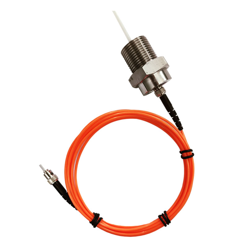
A fluorescence fiber optic temperature monitoring solution works by exciting a rare-earth phosphor element at the tip of the sensing probe with a brief pulse of light from the instrument. The phosphor absorbs the excitation energy and re-emits it as fluorescence — and the time constant of that fluorescence decay, known as the lifetime (τ), shifts in a stable, predictable relationship with temperature. The instrument measures τ and converts it to a calibrated temperature value.
The critical engineering advantage of this approach is that the measurement is based on time — how long the fluorescence takes to decay — rather than on light intensity. This means that anything that reduces the optical power in the system — fiber aging, connector fouling, light source dimming — has no effect on the measured temperature. The decay time at a given temperature is a fixed physical property of the phosphor material; it does not change as the optical system ages. This is why fluorescence-based fiber optic temperature solutions maintain their accuracy over decades of unattended, in-service operation without recalibration.
Multi-Point Coverage from a Single Instrument
A single fiber optic temperature transmitter manages multiple independent sensing channels simultaneously — with each channel connecting to its own probe at a separate measurement location. This makes it possible to build a comprehensive, structured thermal monitoring network across a piece of equipment or an entire installation from a single instrument and a single RS485 network connection. Channel count is configurable to match the specific monitoring requirements of each installation.
Where Fluorescence Fiber Optic Solutions Excel
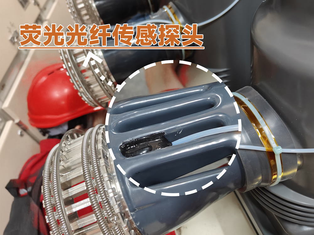
The combination of complete electrical isolation, fast thermal response, stable long-term accuracy, and compact probe geometry makes fluorescence fiber optic temperature solutions the definitive choice for monitoring discrete critical points in electrically demanding environments: the contact surfaces of live high-voltage switchgear, the windings of oil-filled power transformers, the cell-level thermal management of lithium battery energy storage systems, the interior of MRI scanners and other medical imaging equipment, and the reaction-critical locations in chemical and pharmaceutical process reactors.
5. Distributed Fiber Optic Temperature Sensing: Continuous Thermal Mapping Along the Full Route

A distributed fiber optic temperature sensing system uses an ordinary single-mode or multi-mode optical fiber cable as a continuous, unbroken array of temperature sensors — with every meter of the fiber contributing an independent temperature reading. The physical principle is Raman backscattering: when a laser pulse travels down the fiber, a small fraction of the light scatters back toward the instrument. The ratio of two components of that backscattered signal encodes the local temperature at each scattering point, and the round-trip travel time of each returning segment encodes its physical position along the fiber with meter-level precision.
The output of a DTS instrument is a thermal profile — a continuous graph of temperature versus distance along the entire sensing fiber. Every meter of the sensing route is covered simultaneously, with no gaps and no predetermined sensor locations. An anomaly that develops anywhere along the route is detected and position-referenced automatically the moment it appears, regardless of whether that location was anticipated as a risk point during system design.
The Defining Capability: Finding the Fault You Didn’t Know to Look For
The operational value of a distributed temperature sensing solution lies specifically in its ability to detect thermal anomalies at locations that were not identified as risk points in advance. In a power cable tunnel, the joint that overheats may not be the one flagged in the installation survey. In a pipeline, the leak that develops may be at an unremarkable section of straight pipe rather than at a fitting. In a railway tunnel, a fire may ignite from any one of a thousand possible ignition sources distributed along the entire tunnel length. DTS covers all of these locations simultaneously, continuously, with no additional sensors and no additional cost per monitored meter.
Where Distributed Fiber Optic Solutions Excel
Distributed temperature sensing solutions are the standard technology for long-route infrastructure monitoring: power cable tunnels and trays where the full-length thermal profile of every cable circuit is required, oil and gas pipelines where leak detection depends on the temperature signature of escaping product, railway and metro tunnels where fire detection must cover the full tunnel bore without gaps, dam embankments and geotechnical structures where distributed temperature differential reveals groundwater movement, and perimeter security systems where thermal disturbance along a boundary fence must be located to within meters.
6. Side-by-Side: Fluorescence vs DTS Fiber Optic Temperature Solutions
| Parameter | Fluorescence Fiber Optic Solution | Distributed Temperature Sensing (DTS) Solution |
|---|---|---|
| Sensing principle | Fluorescence lifetime decay (photoluminescence) | Raman backscattering |
| Measurement geometry | Point / multi-point at known locations | Continuous — every meter along the full fiber length |
| Temperature accuracy | ±0.5–1°C | ≤±1°C |
| Temperature range | −40°C to +260°C | −50°C to +200°C |
| Sensing range per channel | 0–20 m per probe | ≥30 km per channel |
| Channels per instrument | 1–64 independent probe channels | 2 channels per host unit |
| Spatial positioning | Fixed probe location (defined at installation) | ±1 m along the full sensing route |
| Response time | <1 second per channel | ≤1 second per km per channel |
| High-voltage insulation | >100 kV — fully dielectric probe | Standard fiber dielectric insulation |
| Probe / cable diameter | 2–3 mm (customizable) | Standard armored sensing cable |
| Sensor lifespan | >25 years | >20 years (host unit and laser source) |
| Laser safety | — | IEC 60825-1 Class 1 certified |
| Communication interface | RS485 / Modbus RTU | RS232 / RS485 / Modbus RTU |
| Third-party certifications | Available on request | EMC, positioning accuracy, temperature accuracy, response time — supplied |
| Primary application fit | Discrete equipment hot-spot monitoring at known critical points | Long-route infrastructure continuous thermal surveillance |
7. Fiber Optic Thermal Monitoring Across Industries
Power Utilities: Switchgear, Transformers, and Cable Infrastructure
The power sector was the first major adopter of fiber optic temperature monitoring solutions at scale, driven by the combination of high-voltage isolation requirements and the critical consequences of undetected thermal faults. Fiber optic switchgear temperature monitoring places fluorescence probes directly on circuit breaker contacts, busbar joints, and cable terminations inside live medium-voltage panels — the only contact measurement technology that satisfies the dielectric requirements of these locations. Transformer winding temperature monitoring uses oil-immersed fluorescence probes to measure the actual hot-spot temperature in each winding directly, providing the data needed for IEC 60076-7 insulation life calculations and dynamic loading decisions. For the cable infrastructure feeding and connecting these assets, distributed temperature sensing solutions provide continuous thermal mapping of the full cable route — detecting overloaded joints and insulation degradation before they reach the threshold for cable failure.
Energy Storage: Battery Thermal Management and Runaway Prevention
Lithium-ion battery energy storage systems present one of the most demanding thermal monitoring requirements in any industry. Thermal runaway — the self-sustaining, self-accelerating temperature rise that leads to battery fire — is preceded by a temperature signature that is detectable with a fast, accurate sensor positioned at the cell or module level. Fluorescence fiber optic temperature sensors installed within battery packs provide per-cell or per-module real-time thermal data with response times fast enough to detect the early-stage temperature rise before runaway propagates. The 2–3 mm probe diameter fits within standard cell holder geometries, and the fully dielectric probe creates no conductive path that could contribute to a short-circuit fault in the battery system.
Oil, Gas, and Petrochemical: Hazardous Area Process Monitoring
Refineries, chemical plants, and offshore platforms combine process temperatures that exceed the range of many conventional sensors with Zone 1 and Zone 2 hazardous area classifications that restrict the use of electrically active devices. Fiber optic process temperature monitoring solutions address both constraints simultaneously: the fluorescence probe covers temperatures well above the limits of standard industrial sensors, while the zero-energy, passive nature of the probe makes it intrinsically compatible with explosive atmosphere requirements. Distributed temperature sensing solutions monitor the thermal condition of long pipeline runs and storage tank farms, detecting leak-related temperature anomalies and identifying hotspot locations for maintenance dispatch without the cost and safety risk of physical inspection rounds.
Rail and Transit Infrastructure: Tunnel Fire Detection and Traction Monitoring
Railway and metro tunnels present a fire detection challenge that no point-sensor system can solve economically: the monitored length may extend for kilometers, the potential ignition point is anywhere along the tunnel, and the consequences of a delayed detection are severe. Distributed fiber optic fire detection solutions provide continuous thermal surveillance along the full tunnel bore, generating a position-referenced alarm within seconds of a temperature exceedance anywhere along the sensing fiber. For traction power infrastructure, fluorescence fiber optic solutions monitor the thermal condition of switchgear contacts and transformer windings in railway substations under the heavily cyclic load profiles characteristic of train operation.
Data Centers: Thermal Management and Capacity Planning
Data center operators managing high-density compute infrastructure need thermal visibility at both the room level — airflow patterns, hot and cold aisle temperatures, cooling system performance — and the equipment level — individual server inlet temperatures, busway tap-off temperatures, PDU output thermal loading. Distributed fiber optic temperature solutions provide room-level thermal mapping without a dense grid of discrete sensors. Fluorescence fiber optic solutions provide equipment-level precision at power distribution points where contact temperature is the critical reliability parameter. Together, they form a complete thermal management infrastructure for any data center scale.
Medical and Scientific: EMI-Free Temperature Measurement in Controlled Environments
MRI scanners, particle accelerators, and high-field laboratory electromagnets create magnetic field environments in which any metallic object — including a thermocouple lead or RTD cable — experiences strong induced forces and generates significant electromagnetic interference with the field itself. Fiber optic temperature measurement solutions based on fluorescence sensing are the standard approach for temperature monitoring inside these environments: no metallic sensing element, no susceptibility to magnetic fields, no interference with the field being generated by the instrument. The same properties make fluorescence solutions appropriate for RF-shielded environments, microwave processing equipment, and any other application where electromagnetic cleanliness at the measurement point is a hard requirement.
8. System Integration, Communication, and Deployment Options
Standard Industrial Communication for Seamless SCADA Integration
Both fluorescence and DTS fiber optic temperature monitoring solutions communicate over RS485 using the Modbus RTU protocol — the universal standard for industrial serial communication that is natively supported by every major SCADA, DCS, BMS, and substation automation platform in current production use. Integration with the site control system requires only the Modbus register map — supplied with each instrument — and standard serial communication configuration work. No protocol converters, no custom drivers, and no proprietary software licenses are required.
Wired and Wireless Deployment Flexibility
For sites with existing cable infrastructure, RS485 wired communication is the simplest and most reliable integration path. For remote, unmanned, or geographically dispersed installations — rural substations, pipeline monitoring stations, offshore platforms — wireless communication over 4G LTE or LoRaWAN provides the same data delivery capability without new cable installation. Both communication paths present identical data to the supervisory platform; the choice between wired and wireless is determined entirely by site infrastructure, not by any difference in monitoring capability.
Cloud-Based and On-Premise Supervisory Options
For asset owners managing multiple monitoring points across distributed sites, a cloud-hosted supervisory platform provides fleet-level thermal visibility from any network-connected device — historical trends, alarm records, and condition summaries for every monitored asset in a single portal. For installations with stringent data security requirements or limited network connectivity, the same supervisory functionality is available in an on-premise deployment with no external network dependency. The monitoring hardware is identical in both deployment modes.
9. Choosing the Right Fiber Optic Temperature Monitoring Solution
Start with the Measurement Geometry
The first and most important selection question for any fiber optic temperature monitoring solution is not about specifications — it is about geometry. Are the monitoring targets specific, known locations on equipment or infrastructure? Or is the monitoring requirement defined by a route or area where a thermal anomaly could develop at any point? If the answer is specific known locations, the solution is fluorescence fiber optic sensing. If the answer is a route or area with unknown fault location, the solution is distributed temperature sensing. In many large installations, the answer is both — and the most effective architecture deploys both technologies in complementary roles.
Fluorescence Is the Right Choice When:
- The monitoring targets are specific, pre-identified points on equipment — contacts, joints, windings, cells
- The environment involves high voltage, strong magnetic fields, or explosive atmosphere classifications
- Sub-second thermal response is required — battery runaway prevention, power electronics protection
- A scalable multi-point network serving up to 64 channels from a single transmitter is needed
- The temperature range or accuracy requirement exceeds what conventional sensors can deliver reliably
Distributed Sensing Is the Right Choice When:
- Coverage must extend across hundreds of meters to tens of kilometers without blind spots
- The fault or thermal anomaly location is not known in advance
- Spatial localization of a hot spot to within one meter is required for incident response
- The infrastructure is linear — cable routes, pipelines, tunnels, embankments, perimeter boundaries
- A single instrument must simultaneously cover two independent sensing routes
Combining Both Technologies: The Complete Fiber Optic Thermal Monitoring Architecture
The most comprehensive fiber optic temperature monitoring solution for a large installation is a layered architecture that uses distributed sensing for route-level surveillance and fluorescence sensing for equipment-level precision. A power substation, for example, benefits from DTS monitoring of the cable circuits feeding and leaving the site — covering kilometers of underground cable with a single instrument — and fluorescence monitoring of the switchgear contacts, transformer windings, and battery backup system inside the substation building. Both systems feed into the same Modbus network and the same supervisory platform, providing thermal visibility from the transmission cable to the individual contact surface in a single, unified view.
10. Frequently Asked Questions
Q1: What makes fiber optic temperature monitoring solutions better than conventional sensors for industrial applications?
The fundamental advantage is the sensing medium. Glass fiber conducts light, not electricity — so a fiber optic temperature sensor creates no conductive path into the monitored equipment, is immune to electromagnetic interference, cannot ignite a flammable atmosphere, and maintains its accuracy over decades without recalibration. These are physical properties of the sensing material, not engineering features that can be replicated by improving a conventional sensor design.
Q2: Can fiber optic temperature solutions be used in both high-voltage and low-voltage applications?
Yes. Fluorescence fiber optic probes are rated above 100 kV and can be installed directly on energized medium-voltage and high-voltage conductors without additional isolation hardware. The same probe technology is equally applicable in low-voltage applications — motor control centers, battery systems, data center power distribution — where the dielectric rating provides a large safety margin over the system voltage. The fully dielectric probe creates no conductive path regardless of the system voltage at the installation point.
Q3: How does distributed temperature sensing locate a hot spot along a long fiber route?
The DTS instrument measures the round-trip travel time of each segment of Raman backscattered light returning along the fiber. Since light travels through optical fiber at a known, constant velocity, the travel time precisely encodes the distance from the instrument to each measurement point. This allows the system to report both the temperature value and the physical position of any thermal anomaly along the full sensing route, with a location accuracy of ±1 m regardless of the total route length.
Q4: How many monitoring points can one fiber optic transmitter cover?
A single fluorescence fiber optic temperature transmitter supports 1 to 64 independent sensing channels, each connected to its own probe at a separate measurement location. All channels are interrogated continuously and the readings from all channels are available simultaneously on the RS485 output. For installations requiring more than 64 points, additional transmitters are connected to the same RS485 network, each with a unique Modbus address, and the supervisory platform aggregates all data into a single monitoring view.
Q5: What is the difference between fluorescence lifetime sensing and intensity-based fiber optic sensing?
Intensity-based fiber optic sensing measures how much light returns from the sensing element — and that measurement changes whenever anything in the optical path changes, including fiber bending, connector contamination, or light source aging. Fluorescence lifetime sensing measures how long the fluorescence takes to decay — a time-domain measurement that is completely independent of optical power levels. Because the decay time is a physical property of the phosphor material at a given temperature, it is unaffected by anything that happens to the light intensity in the system. This is why lifetime-based solutions maintain accuracy over decades without recalibration, while intensity-based approaches require periodic recalibration to correct for optical path changes.
Q6: Are fiber optic temperature monitoring solutions compatible with hazardous area installations?
Yes. The passive, zero-energy nature of a fluorescence fiber optic probe — which carries and stores no electrical energy at the sensing point — makes it intrinsically compatible with hazardous area deployments. The probe presents no ignition source under any operating or fault condition. Monitoring instruments are located outside the hazardous zone boundary, and the fiber connection crosses the zone boundary without any conductive path. Project-specific zone classification and applicable ATEX or IECEx certification requirements should be confirmed with the relevant authority for each installation.
Q7: How do fiber optic temperature solutions integrate with existing SCADA or building management systems?
Both fluorescence transmitters and DTS host units communicate over RS485 using Modbus RTU — the universal industrial serial protocol supported natively by all major SCADA, DCS, BMS, and substation automation platforms. Integration requires only the Modbus register map, which is supplied with each instrument, and standard serial communication configuration work on the supervisory platform. For IEC 61850-compliant substation automation systems, a standard Modbus-to-IEC 61850 gateway provides the protocol conversion without any modification to the monitoring hardware.
Q8: What maintenance do fiber optic temperature monitoring solutions require?
Fluorescence fiber optic probes require no scheduled maintenance — their rated operational lifespan exceeds 25 years under normal service conditions, and the lifetime measurement principle does not drift with age or optical path changes. DTS host units and their laser sources are rated for over 20 years of continuous operation. Periodic functional verification — confirming that all channels read correctly against a reference temperature — is the only routine maintenance task. No recalibration intervals, no consumable replacements, and no access to the sensing elements in the field are required under normal operating conditions.
Q9: Can fluorescence and DTS monitoring systems operate together on the same network?
Yes. Both technologies use RS485 with Modbus RTU as their standard communication interface. A fluorescence transmitter and a DTS host unit can share the same RS485 bus, each with a unique Modbus slave address, and both are polled by the same supervisory platform master. This is the standard configuration for layered monitoring architectures that combine equipment-level fluorescence point monitoring with infrastructure-level DTS route monitoring — both technologies deliver their data to a single control system interface with no additional hardware.
Q10: What is the typical service life of a fiber optic temperature monitoring installation?
A well-specified fiber optic temperature monitoring system is designed to remain in continuous service for the operational life of the monitored asset. Fluorescence probe lifespan exceeds 25 years; DTS host and laser lifespan exceeds 20 years. In practice, fiber optic monitoring installations routinely outlast the scheduled maintenance intervals of the electrical equipment they monitor — in many cases remaining in service through one or more major equipment refurbishments without requiring replacement of the sensing elements. This longevity, combined with the absence of scheduled recalibration requirements, makes the total cost of ownership of a fiber optic thermal monitoring solution significantly lower than any sensor technology requiring periodic replacement or recalibration over the same service period.
11. Explore Our Fiber Optic Temperature Monitoring Solutions
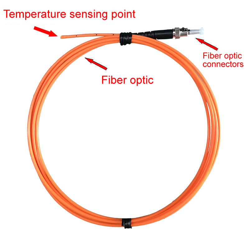
Fuzhou Innovation Electronic Scie&Tech Co., Ltd. has designed and manufactured fiber optic solutions for temperature monitoring since 2011. Our product range covers fluorescence fiber optic temperature probes, multi-channel fiber optic temperature transmitters, and distributed fiber optic temperature sensing (DTS) systems — serving power utilities, energy storage, petrochemical, rail infrastructure, data center, and medical equipment applications worldwide.
Contact our engineering team to request product datasheets, discuss a specific application, or arrange a technical consultation:
- Website: www.fjinno.net
- Email: web@fjinno.net
- WhatsApp / WeChat (China) / Phone: +86 135 9907 0393
- QQ: 3408968340
- Address: Liandong U Grain Networking Industrial Park, No.12 Xingye West Road, Fuzhou, Fujian, China
Disclaimer: The technical information in this article is provided for general informational purposes only and reflects standard product parameters and industry practice at the time of publication. Actual system performance may vary depending on installation conditions, environmental factors, and application requirements. All specifications are subject to change without notice. This content does not constitute a warranty, binding technical commitment, or engineering design recommendation for any specific installation. Consult a qualified engineer and applicable standards documentation for project-specific design and safety decisions.

Fiber optic temperature sensor, Intelligent monitoring system, Distributed fiber optic manufacturer in China
 |
 |
 |