 INNO fibre optic temperature sensors ,temperature monitoring systems.
- Power monitoring systems reduce equipment failure rates by 60-80% through real-time condition assessment
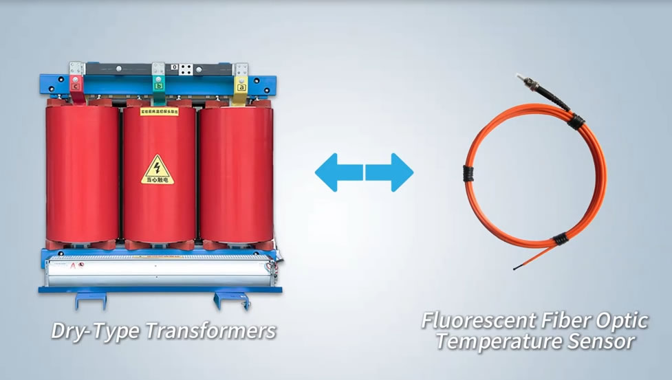
- Fiber optic temperature sensors provide complete immunity to electromagnetic interference in high-voltage environments
- Fluorescent fiber optic sensors deliver ±1°C accuracy with response time under 1 second
- Single monitoring unit supports 1-64 temperature measurement channels via fiber optic technology
- Distributed temperature sensing (DTS) monitors continuous temperature profiles across kilometers of power cables
- Early detection of thermal anomalies prevents catastrophic equipment failures 3-6 months in advance
- Fiber optic sensors offer intrinsic electrical isolation, eliminating safety concerns in high-voltage applications
- Temperature monitoring integrated with partial discharge and load data provides comprehensive asset health assessment
- Cloud-based platforms enable centralized monitoring of hundreds of substations from a single interface
- Systems comply with IEC 61850, IEEE C57.91, and other international power industry standards
Table of Contents
- What is a Power Monitoring System?
- What is an Electrical Power Monitoring System?
- Industrial Power Monitoring System: Definition and Scope
- Key Components of a Power Monitoring System
- How Power Monitoring Systems Work
- Why Power Monitoring is Critical for Electrical Infrastructure
- Types of Power Monitoring Systems
- Fiber Optic Temperature Sensors: The Superior Choice
- Point Temperature Measurement with Fluorescent Fiber Optic Sensors
- Fluorescent Fiber Optic Sensors vs Other Technologies
- Top 10 Benefits of Power Monitoring Systems
- Where are Power Monitoring Systems Used?
- Transformer Temperature Monitoring Solutions
- Switchgear and GIS Monitoring Applications
- Power Cable and Cable Joint Monitoring
- How to Choose the Best Power Monitoring System
- Case Study: 220kV Transformer Monitoring
- Leading Fiber Optic Power Monitoring Manufacturer
- Frequently Asked Questions
1. What is a Power Monitoring System?
A power monitoring system is an integrated solution that continuously tracks the operational condition and performance of electrical equipment through real-time data collection and analysis. These systems employ various sensors to measure critical parameters including temperature, partial discharge, load current, voltage, and environmental conditions.
Unlike traditional periodic inspection methods, modern power monitoring systems provide 24/7 surveillance of electrical assets, enabling operators to detect abnormal conditions before they escalate into failures. The core value lies in transitioning from reactive maintenance to predictive maintenance strategies.
Primary Functions
Power monitoring systems serve three essential functions: early fault detection through continuous parameter tracking, equipment health assessment via trend analysis, and operational optimization by providing actionable insights for load management and maintenance planning.

2. What is an Electrical Power Monitoring System?
An electrical power monitoring system specifically focuses on monitoring electrical parameters and thermal conditions within power distribution networks. These systems integrate hardware components such as sensors, data acquisition units, and communication interfaces with software platforms for data visualization and alarm management.
In utility applications, electrical power monitoring systems track substation equipment including transformers, circuit breakers, and bus systems. The emphasis is on preventing unplanned outages that can affect thousands of customers and result in significant financial losses.
Key Monitored Parameters
Temperature remains the most critical parameter, as thermal anomalies account for 40-60% of electrical equipment failures. Other monitored parameters include partial discharge activity indicating insulation degradation, load current for capacity management, and oil quality in liquid-filled equipment.

3. Industrial Power Monitoring System: Definition and Scope
An industrial power monitoring system addresses the unique requirements of manufacturing facilities, process plants, and large commercial installations. These environments demand higher reliability due to the direct correlation between power quality and production efficiency.
Industrial power monitoring systems typically monitor in-plant distribution equipment including medium-voltage switchgear, large motors, generators, and power factor correction equipment. The focus extends beyond fault prevention to include energy efficiency optimization and power quality management.
Industrial vs Utility Applications
While utility systems prioritize grid reliability and regulatory compliance, industrial systems emphasize production continuity and energy cost reduction. Industrial environments often present more challenging conditions including heavy electromagnetic interference, extreme temperatures, and harsh chemical atmospheres.
4. Key Components of a Power Monitoring System
A comprehensive power monitoring system consists of four main layers working in coordination.
Sensor Layer
Fiber optic temperature sensors form the foundation of modern monitoring systems, offering intrinsic electrical isolation and EMI immunity. Fluorescent fiber optic sensors measure point temperatures with high accuracy, while distributed temperature sensing systems monitor temperature profiles along power cables.
Data Acquisition Layer
Signal conditioning units and data loggers collect sensor outputs and convert them into digital formats. Modern systems utilize high-speed sampling to capture transient events while employing data compression for efficient storage.
Communication Layer
Industrial protocols including Modbus TCP, IEC 61850, and DNP3 enable seamless integration with existing SCADA infrastructure. Communication options range from hardwired Ethernet to wireless 4G/5G connectivity for remote sites.
Application Layer
Software platforms provide real-time visualization, historical trending, alarm management, and reporting capabilities. Cloud-based solutions enable multi-site monitoring from centralized control rooms.
5. How Power Monitoring Systems Work
Power monitoring systems operate through continuous sensing, data transmission, analysis, and response workflows.
Continuous Sensing
Fluorescent fiber optic temperature sensors installed at critical points—such as transformer windings, switchgear contacts, and cable joints—measure temperature with sub-second response times. The sensors operate on the principle of temperature-dependent fluorescence lifetime in rare-earth materials.
Data Processing and Analysis
Monitoring units process sensor signals and compare measurements against pre-defined alarm thresholds. Advanced systems employ trend analysis algorithms to detect gradual temperature increases that may indicate developing faults.
Alarm Generation and Response
When parameters exceed warning levels, the system generates alarms via multiple channels including SMS, email, and mobile app notifications. Integration with SCADA systems enables automated load shedding or equipment tripping for severe conditions.
6. Why Power Monitoring is Critical for Electrical Infrastructure
The criticality of electrical power monitoring systems stems from both economic and safety imperatives.
Economic Impact of Equipment Failures
Unplanned outages in industrial facilities cost an average of $50,000 to $500,000 per hour depending on the industry sector. For utilities, major equipment failures can result in multi-million dollar replacement costs plus regulatory penalties for service reliability violations.
Aging Infrastructure Challenge
Over 40% of transformers in service globally exceed 30 years of age, approaching or surpassing their designed service life. Power monitoring systems enable condition-based lifetime extension by identifying specific components requiring attention rather than wholesale equipment replacement.
Safety Considerations
Thermal runaway in electrical equipment poses fire and explosion risks. Early detection through continuous temperature monitoring prevents catastrophic failures that could endanger personnel and facilities.
7. Types of Power Monitoring Systems
Power monitoring systems can be categorized by scope, technology, and application.
By Monitoring Scope
Single-parameter systems focus exclusively on temperature or partial discharge, offering simplicity and lower cost. Multi-parameter systems integrate temperature, partial discharge, load, and environmental monitoring for comprehensive asset management.
By Sensing Technology
Fiber optic monitoring systems utilize light-based sensors immune to electromagnetic interference. Wireless systems employ battery-powered or energy-harvesting sensors for retrofit applications. Hybrid systems combine multiple technologies to optimize coverage and cost.
By Application Level
Equipment-level systems monitor individual assets such as a single transformer or switchgear lineup. Substation-level systems provide integrated monitoring across all critical equipment. Network-level systems aggregate data from multiple substations for fleet management.
8. Fiber Optic Temperature Sensors: The Superior Choice
Fiber optic temperature sensors have emerged as the preferred technology for electrical power applications due to their unique advantages in high-voltage environments.
Complete Electrical Isolation
Unlike metallic sensors, fiber optic sensors contain no conductive materials. This intrinsic electrical isolation allows direct installation on high-voltage conductors without requiring complex isolation circuitry. The sensors can be safely deployed on equipment operating at hundreds of kilovolts.
100% EMI Immunity
Electromagnetic interference from switchgear operations, partial discharge events, and high-current circuits renders traditional electronic sensors unreliable. Fiber optic temperature sensors are completely immune to EMI, ensuring accurate measurements even in the most electrically noisy environments.
Long-Distance Signal Transmission
Optical signals propagate through fiber with negligible loss over distances exceeding 5 kilometers. This capability enables centralized monitoring equipment to serve sensors distributed across large substations or industrial facilities without signal degradation.
Intrinsic Safety
The absence of electrical power at the sensor eliminates ignition sources, making fiber optic sensors inherently safe for hazardous locations without requiring special enclosures or barriers.
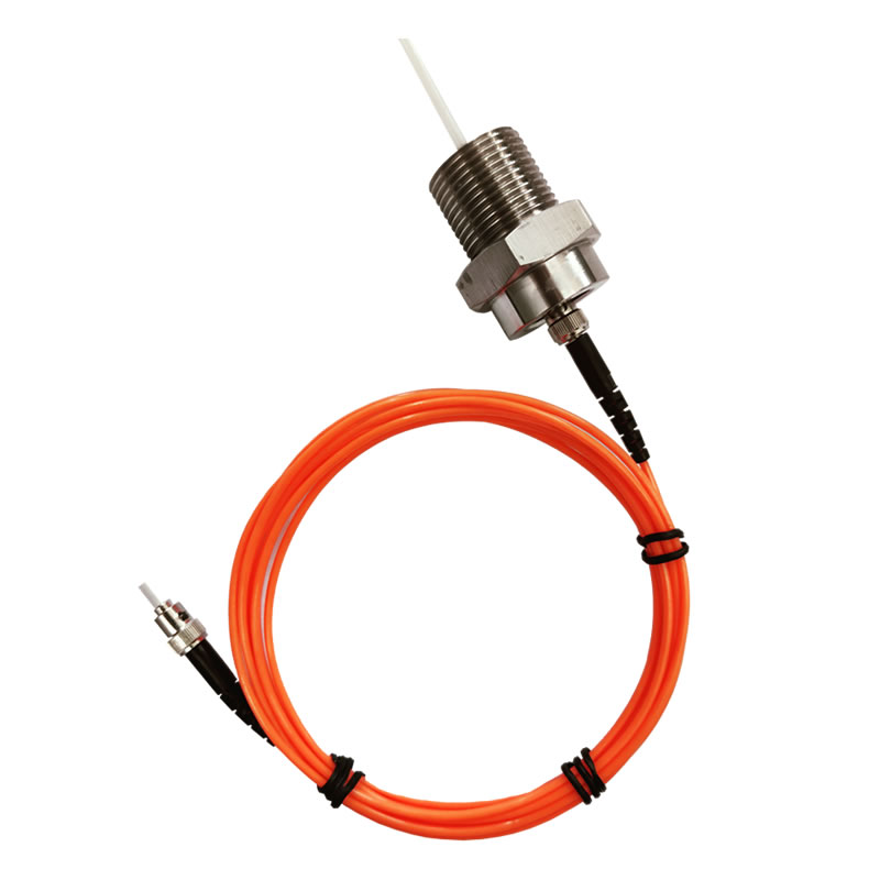
9. Point Temperature Measurement with Fluorescent Fiber Optic Sensors
Fluorescent fiber optic sensors represent the most widely deployed point-measurement technology in power monitoring systems.
Operating Principle
The sensing element contains rare-earth phosphor materials that exhibit temperature-dependent fluorescence decay characteristics. When excited by a light pulse from the interrogator unit, the phosphor emits fluorescence with a decay time inversely proportional to temperature. This physical relationship provides inherently stable calibration.
Technical Specifications
Fluorescent fiber optic temperature sensors deliver exceptional performance characteristics for power applications:
- Measurement Accuracy: ±1°C across the full operating range
- Temperature Range: -40°C to +260°C, covering all power equipment requirements
- Response Time: Less than 1 second, enabling detection of rapid thermal transients
- Fiber Length: 0 to 80 meters between sensor and interrogator, providing installation flexibility
- Probe Diameter: Customizable from 1mm to 6mm to fit tight spaces or provide thermal mass
- Channel Capacity: Single interrogator unit supports 1 to 64 independent temperature channels
Multi-Channel Architecture
The ability to connect up to 64 sensors to one monitoring unit provides significant system advantages. A single unit can monitor all three phases of a transformer winding at multiple depths, or survey an entire switchgear lineup with contacts, bus connections, and cable terminations.
10. Fluorescent Fiber Optic Sensors vs Other Technologies

| Feature | Fluorescent Fiber Optic | FBG Fiber Optic | Wireless Sensors | RTD/Thermocouple | Infrared Thermal |
|---|---|---|---|---|---|
| Electrical Isolation | Excellent (Complete) | Excellent (Complete) | Good | Poor (Requires isolation) | Non-contact |
| EMI Immunity | Excellent (100%) | Excellent (100%) | Moderate | Poor | Excellent |
| Accuracy | ±1°C | ±0.5-2°C | ±1-2°C | ±0.1-0.5°C | ±2-5°C |
| Response Time | <1 second | <1 second | 5-30 seconds | 1-10 seconds | Real-time |
| Multi-Point Capability | Excellent (64 channels) | Good (Quasi-distributed) | Good (Multi-node) | Poor (Single point) | Excellent (Area array) |
| Service Life | 20+ years | 15+ years | 3-5 years (Battery) | 5-10 years | 10+ years |
| Maintenance | Maintenance-free | Maintenance-free | Battery replacement | Periodic calibration | Lens cleaning |
| Typical Applications | Transformers, Switchgear | Cables, Structures | Switchgear contacts | Legacy systems | Inspection, Surveys |
Fluorescent fiber optic sensors provide the optimal balance of accuracy, reliability, and practicality for permanent installation in electrical power monitoring systems. The complete EMI immunity and electrical isolation enable deployment in locations where other technologies would fail or require expensive isolation measures.
11. Top 10 Benefits of Power Monitoring Systems
1. Early Fault Detection
Power monitoring systems identify developing problems months before failure occurs, enabling scheduled repairs during planned outages rather than emergency response to equipment breakdowns.
2. Reduced Downtime
By preventing unexpected failures, monitoring systems dramatically reduce unplanned outages. Industrial facilities report downtime reductions of 60-80% after implementing comprehensive monitoring.
3. Extended Equipment Life
Operating equipment within safe thermal limits prevents accelerated aging. Monitoring data supports condition-based maintenance that can extend transformer service life by 5-10 years beyond rated expectations.
4. Optimized Maintenance
Maintenance transitions from time-based schedules to condition-based interventions, reducing unnecessary inspections while ensuring critical maintenance occurs when needed.
5. Improved Safety
Early detection of overheating prevents fires and explosions. Personnel safety improves through reduced need for manual inspections in hazardous areas.
6. Load Optimization
Real-time thermal monitoring enables dynamic loading of equipment, safely utilizing capacity that would otherwise remain unused under conservative fixed-rating approaches.
7. Regulatory Compliance
Comprehensive monitoring data demonstrates due diligence to regulatory authorities and insurance carriers, potentially reducing premiums and avoiding penalties.
8. Asset Management
Historical temperature data and event logs provide objective evidence of equipment condition for strategic planning of capital replacements and upgrades.
9. Remote Accessibility
Cloud-based platforms enable monitoring from anywhere, reducing need for on-site personnel at remote installations and enabling expert analysis from central facilities.
10. Rapid ROI
By preventing even a single major failure, power monitoring systems typically pay for themselves within 12-24 months of operation.
12. Where are Power Monitoring Systems Used?
Power monitoring systems find application across the entire electrical power infrastructure spectrum.
Utility Transmission Networks
High-voltage substations from 110kV to 500kV and beyond utilize monitoring for critical assets including power transformers, shunt reactors, and circuit breakers. The high replacement costs and grid stability implications justify comprehensive monitoring.
Distribution Networks
Medium-voltage distribution substations (10kV-35kV) monitor distribution transformers, switchgear, and feeder circuits. The large number of distribution substations makes monitoring economics particularly attractive.
Industrial Facilities
Manufacturing plants, refineries, chemical plants, and mining operations deploy industrial power monitoring systems to protect in-plant distribution equipment and large motors. Production continuity requirements drive adoption.
Commercial Buildings
Data centers, hospitals, airports, and large commercial complexes monitor critical electrical infrastructure to ensure business continuity and meet uptime commitments.
Renewable Energy
Wind farms, solar installations, and battery energy storage systems monitor power conversion equipment including inverters, transformers, and medium-voltage collection systems.
13. Transformer Temperature Monitoring Solutions
Transformer monitoring represents the most critical application for power monitoring systems due to transformer replacement costs ranging from hundreds of thousands to millions of dollars.
Critical Monitoring Points
Winding hotspot temperature determines transformer loading capability and aging rate. Fluorescent fiber optic sensors installed at multiple depths in high-voltage, medium-voltage, and low-voltage windings provide direct hotspot measurement rather than relying on calculation from top-oil temperature.
Multi-Channel Configuration
A typical large power transformer monitoring system employs 9-12 temperature channels: 3-4 points per winding across three phases. This configuration captures thermal asymmetries that could indicate developing faults such as blocked cooling passages or turn-to-turn shorts.
Integration with Other Parameters
Transformer monitoring systems often combine temperature measurement with top-oil temperature, load current, dissolved gas analysis (DGA), and partial discharge monitoring for comprehensive condition assessment.
14. Switchgear and GIS Monitoring Applications

Switchgear monitoring addresses the most common failure mode: overheating at electrical connections due to contact degradation or loose hardware.
Key Monitoring Locations
Critical points include circuit breaker contacts (both fixed and moving), bus bar joints, cable terminations, and current transformer connections. Each three-phase circuit typically requires 6-9 monitoring points.
Compact Installation
The small diameter of fluorescent fiber optic sensor probes (1-3mm typical) enables installation in confined switchgear compartments where larger sensors cannot fit. The flexible fiber allows routing through tight cable passages.
Multi-Bay Monitoring
The 64-channel capacity of modern monitoring units enables a single system to cover an entire switchgear lineup. For a 10-bay medium-voltage switchgear installation with 9 points per bay, two monitoring units provide complete coverage.
15. Power Cable and Cable Joint Monitoring
Power cable monitoring employs both point sensors and distributed sensing depending on cable configuration and length.
Cable Joint Monitoring with Point Sensors
Cable joints and terminations represent weak points prone to overheating. Fluorescent fiber optic sensors attached to joint bodies provide early warning of developing problems. For three-phase cables, 3-6 sensors per joint location ensure complete coverage.
Cable Tunnel Monitoring with DTS
Distributed temperature sensing systems based on Raman scattering monitor temperature continuously along cable routes. A single optical fiber provides temperature measurement at every meter along cables spanning several kilometers, enabling precise localization of hotspots.
Dynamic Rating
Continuous temperature monitoring enables dynamic cable rating that optimizes utilization based on actual thermal conditions rather than conservative worst-case assumptions. This capability can increase effective capacity by 15-30%.
16. How to Choose the Best Power Monitoring System
Selecting an appropriate power monitoring system requires systematic evaluation of requirements and available solutions.
Define Monitoring Objectives
Clarify primary goals: preventing catastrophic failures, optimizing loading, extending equipment life, or meeting regulatory requirements. Different objectives may drive different sensor placement and alarm strategies.
Identify Critical Equipment
Not all equipment warrants monitoring. Focus on assets where failure would cause significant financial loss, safety hazards, or service disruption. Large power transformers, critical switchgear, and high-capacity cables typically receive priority.
Determine Monitoring Parameters
Temperature monitoring provides the foundation for most applications. Consider whether partial discharge, load, or other parameters add sufficient value to justify additional investment.
Evaluate Sensor Technologies
For high-voltage electrical applications, fiber optic temperature sensors offer clear advantages in accuracy, reliability, and safety. The choice between fluorescent and FBG fiber optic sensors depends on specific requirements, with fluorescent systems offering superior accuracy and lower cost for point measurement applications.
Assess Integration Requirements
Determine communication protocol compatibility with existing SCADA or automation systems. Modern monitoring units support standard protocols including Modbus TCP, IEC 61850, and DNP3.
Consider Scalability
Select systems that can expand to accommodate future monitoring needs without requiring replacement of existing infrastructure. Modular systems with support for 64 channels provide room for growth.
Evaluate Supplier Capabilities
Assess technical support, installation assistance, training programs, and warranty terms. Supplier experience in similar applications reduces implementation risk.
17. Case Study: 220kV Transformer Monitoring
Background
A utility company operated a critical 220kV/110kV, 180MVA power transformer serving a major industrial area. The 28-year-old unit showed gradually increasing top-oil temperature over several years, suggesting potential cooling system degradation or winding problems.
Solution Implementation
A 12-channel fluorescent fiber optic temperature monitoring system was installed with sensors positioned at four depths in each of the three winding sections (high-voltage, medium-voltage, and low-voltage). Installation occurred during a scheduled outage without requiring tank entry.
Findings
Monitoring revealed that the B-phase high-voltage winding operated 18°C hotter than the A and C phases under identical loading. This significant asymmetry indicated a localized problem not detectable through conventional top-oil temperature measurement.
Outcome
During the next planned outage, internal inspection identified partial blockage of cooling oil flow to the B-phase winding caused by cellulose debris. Cleaning the cooling passages restored normal thermal balance. The monitoring system prevented what would likely have become an insulation failure within 12-18 months, avoiding a catastrophic failure costing over $3 million in equipment replacement plus substantial outage costs.
Ongoing Benefits
Continued monitoring enables the utility to optimize transformer loading based on actual winding temperatures rather than conservative nameplate ratings, increasing usable capacity by approximately 12% during peak demand periods.
18. Leading Fiber Optic Power Monitoring Manufacturer
Fuzhou Innovation Electronic Scie&Tech Co., Ltd. has specialized in fluorescent fiber optic temperature monitoring systems since 2011, serving utility and industrial customers worldwide.
Core Technologies
Our fiber optic monitoring systems utilize advanced fluorescence lifetime measurement technology optimized for power system applications. Products comply with IEC 61850, IEEE C57.91, and other relevant international standards.
Product Range
- Transformer Winding Temperature Monitoring Systems – 4 to 64 channel configurations
- Switchgear Multi-Point Temperature Monitoring – Compact sensors for confined spaces
- Generator and Motor Monitoring Solutions – Specialized probes for rotating machinery
- Power Cable Joint Monitoring – Weatherproof sensor assemblies
- Custom Engineering Solutions – Application-specific designs for unique requirements
Why Choose Our Solutions
Our systems deliver 100% electromagnetic immunity through pure optical sensing technology. The proven reliability of our fluorescent fiber optic sensors in high-voltage environments provides peace of mind for critical infrastructure protection. Flexible system architecture accommodates installations from single transformers to fleet-wide monitoring across multiple substations.
Technical Support
We provide comprehensive support including application engineering, installation supervision, commissioning assistance, and operator training. Our technical team assists with sensor placement optimization, alarm threshold determination, and SCADA integration.
Contact Information
📧 E-mail: web@fjinno.net
📱 WhatsApp: +86 13599070393
💬 WeChat: +86 13599070393
🆀 QQ: 3408968340
☎️ Phone: +86 13599070393
🏢 Address:
Liandong U Grain Networking Industrial Park,
No.12 Xingye West Road, Fuzhou, Fujian, China
Contact our engineering team to discuss your power monitoring system requirements. We provide technical specifications, system design recommendations, and competitive quotations typically within 24 hours.
19. Frequently Asked Questions
What are the main advantages of fiber optic temperature sensors in power systems?
Fiber optic sensors provide complete electrical isolation, 100% immunity to electromagnetic interference, intrinsic safety in high-voltage environments, and maintenance-free operation exceeding 20 years. These characteristics make them superior to traditional sensors for electrical applications.
Can fluorescent fiber optic sensors be installed on energized equipment?
Yes, fluorescent fiber optic sensors can be installed on energized equipment during outages without special precautions beyond normal electrical safety procedures. The complete electrical isolation eliminates grounding concerns that complicate installation of metallic sensors.
How many temperature points can a single monitoring system handle?
Modern fluorescent fiber optic monitoring systems support 1 to 64 independent temperature measurement channels per unit. Multiple units can be networked to monitor hundreds of points across large installations.
What is the difference between point sensors and distributed temperature sensing?
Point sensors like fluorescent fiber optic sensors measure temperature at specific discrete locations with high accuracy (±1°C) and fast response (<1 second). Distributed temperature sensing measures continuous temperature profiles along fiber optic cables over distances of several kilometers, ideal for monitoring long cable routes.
How accurate are fluorescent fiber optic temperature sensors?
Fluorescent fiber optic sensors achieve ±1°C measurement accuracy across the full -40°C to +260°C range, meeting or exceeding requirements for virtually all power equipment monitoring applications.
Do fiber optic monitoring systems require special maintenance?
No, fiber optic temperature sensors operate maintenance-free throughout their 20+ year service life. Unlike wireless sensors that require battery replacement or traditional sensors requiring periodic calibration, optical sensors maintain accuracy through their inherent physical measurement principle.
Can fiber optic systems integrate with existing SCADA?
Yes, modern monitoring units support standard industrial protocols including Modbus TCP, IEC 61850, DNP3, and OPC UA, enabling seamless integration with existing SCADA and substation automation systems.
What is the typical response time for detecting temperature changes?
Fluorescent fiber optic sensors respond to temperature changes in less than 1 second, enabling rapid detection of fault conditions and supporting protective relaying applications.
How do power monitoring systems prevent equipment failures?
Power monitoring systems detect abnormal temperature increases 3-6 months before failures occur, providing time for scheduled maintenance during planned outages rather than emergency response to unexpected breakdowns.
Are fiber optic sensors affected by electromagnetic interference?
No, fiber optic sensors are completely immune to electromagnetic interference. This immunity ensures accurate measurements even in environments with strong EMI from switchgear operations, partial discharge events, or high-current circuits that would render electronic sensors unreliable.
What communication distances are possible with fiber optic monitoring?
Optical signals in fiber optic monitoring systems can be transmitted over 5 kilometers without repeaters or signal degradation, enabling centralized monitoring equipment to serve sensors distributed across large facilities.
How long do fiber optic temperature sensors last?
Fluorescent fiber optic sensors have demonstrated reliable operation exceeding 20 years in field installations, with the optical sensing principle providing inherently stable long-term performance without drift.
Can monitoring systems detect partial discharge and temperature simultaneously?
Yes, comprehensive power monitoring systems integrate temperature measurement via fiber optic sensors with partial discharge detection using ultrasonic, UHF, or chemical sensing methods to provide multi-parameter condition assessment.
What standards apply to power monitoring systems?
Power monitoring systems should comply with IEC 61850 for substation communication architecture, IEEE C57.91 for transformer loading guides, and relevant electrical safety standards including IEC 60255.
How is ROI calculated for power monitoring systems?
ROI calculation considers avoided failure costs (equipment replacement, outage losses, emergency repairs), optimized maintenance savings, extended equipment life, and improved loading capacity. Most installations achieve payback within 12-24 months through prevention of a single major failure.
Disclaimer
This article provides general information about power monitoring systems and fiber optic temperature sensing technologies for educational purposes. Actual system design, equipment selection, installation, and operation must be performed by qualified electrical engineers and technicians in accordance with applicable local electrical codes, utility standards, and safety regulations. Equipment specifications, performance characteristics, and application suitability vary by manufacturer and specific product model.
Fuzhou Innovation Electronic Scie&Tech Co., Ltd. does not assume liability for any damages, losses, injuries, or consequences resulting from the use or misuse of information contained in this article. Readers should consult with qualified professionals and refer to manufacturer documentation for specific technical guidance related to their applications. Standards and regulations referenced herein are subject to updates and revisions; users should verify current versions applicable to their jurisdiction.
For authoritative technical specifications, installation guidelines, and safety information regarding our products, please contact our engineering support team directly.

Fiber optic temperature sensor, Intelligent monitoring system, Distributed fiber optic manufacturer in China
 |
 |
 |