 INNO fibre optic temperature sensors ,temperature monitoring systems.
- Partial discharge thermal hotspot monitoring prevents catastrophic equipment failures in switchgear, transformers, and cable joints
- Fluorescent fiber optic sensors provide ±1.0°C accuracy with 100kV voltage withstand capability in high-voltage environments
- Integrated monitoring systems combine PD detection (0-1000pC) with multi-channel temperature tracking for comprehensive diagnostics
- Manufacturers offer OEM/ODM customized solutions with flexible configurations from 1-32 measurement channels
- Factory-direct wholesale pricing available for bulk orders with global export capabilities
1. What Is Partial Discharge and Thermal Hotspot Formation

1.1 Understanding Partial Discharge Phenomena
Partial discharge (PD) occurs when electrical insulation experiences localized breakdown without completely bridging conductors. In switchgear, transformers, and cable systems, PD manifests as repetitive micro-sparks that gradually degrade insulation materials. These discharges generate heat, ozone, and chemical byproducts that accelerate equipment deterioration.
1.2 How Thermal Hotspots Develop
Thermal hotspots form when PD activity, poor electrical connections, or overloading create localized heating. In circuit breakers and busbar connections, contact resistance increases temperature. Cable joints suffer from installation defects that produce heat concentration. Left undetected, these hotspots escalate from minor anomalies to catastrophic failures.
| Equipment Type | Common PD Locations | Typical Discharge Type | Failure Risk |
|---|---|---|---|
| Switchgear | Cable terminals, busbar joints, circuit breaker contacts | Surface discharge, corona | High |
| Transformers | Winding insulation, tap changers, bushings | Internal cavity discharge | Critical |
| Cable Joints | Splice connections, terminations | Interface discharge | High |
| GIS Equipment | Spacer insulators, particle contamination | Free particle discharge | Medium |
2. Why Partial Discharge Thermal Hotspot Monitoring Is Critical

2.1 Preventing Equipment Failures
Unmonitored partial discharge activity leads to insulation breakdown, causing unplanned outages and equipment damage. Online monitoring systems detect PD inception at 0-1000pC levels, enabling intervention before critical failure. Combined thermal hotspot detection identifies overheating from 40°C below zero to 200°C, covering the full operational envelope.
2.2 Economic Benefits
Condition-based maintenance reduces costs by 30-50% compared to time-based schedules. Early hotspot detection prevents emergency repairs and extends asset lifespan. For a medium-voltage switchgear installation, monitoring systems typically achieve ROI within 18-24 months through avoided failures alone.
| Comparison Factor | Traditional Inspection | Online Monitoring |
|---|---|---|
| Detection Speed | Monthly/Quarterly | Real-time continuous |
| Failure Prevention | Reactive | Predictive |
| Maintenance Cost | High (scheduled + emergency) | Optimized (condition-based) |
| Safety Risk | Personnel exposure during inspection | Remote monitoring |
3. Partial Discharge Detection Equipment and Technology
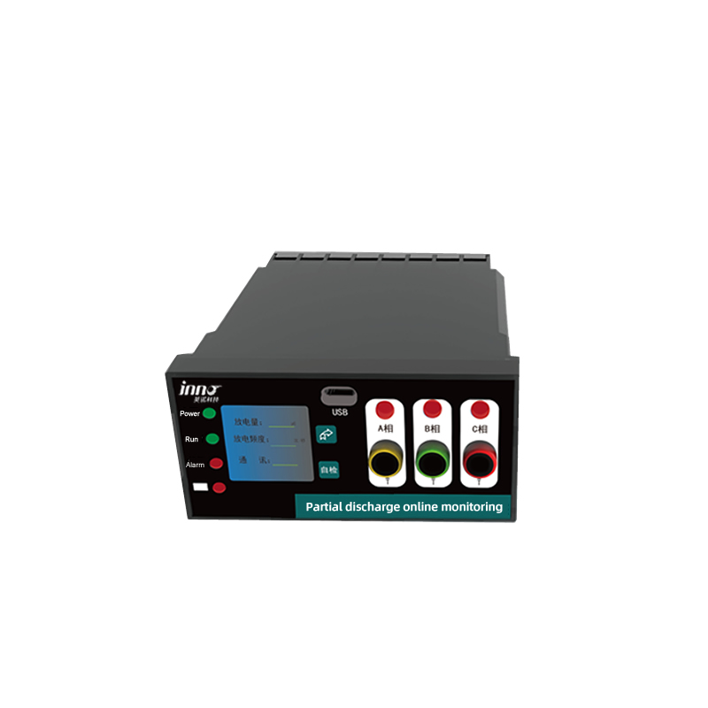
3.1 How PD Monitoring Systems Work
Partial discharge monitoring devices employ capacitive coupling to detect high-frequency pulses generated by discharge events. The system measures discharge magnitude in picocoulombs (pC), providing quantitative assessment of insulation condition. Modern units integrate LCD displays showing energization status and support RS485/433MHz communication for centralized monitoring.
| Parameter | Specification | Notes |
|---|---|---|
| Operating Voltage | AC 220V 50Hz | Standard power supply |
| Communication | RS485/433MHz | Wired and wireless options |
| Measurement Range | 0-1000pC | Customizable per application |
| Display | LCD with energization indicator | LED shows cabinet energization |
| Interface | USB-B/RJ45 Ethernet | Multiple connectivity |
| Coupling Capacitor | 3PF-150PF | Design-dependent, custom options |
| Voltage Rating | 5kV-36kV | Application-specific |
4. Fluorescent Fiber Optic Temperature Monitoring Solutions

4.1 Why Fiber Optic Sensors for High Voltage
Fluorescent fiber optic temperature sensors utilize non-conductive quartz fibers immune to electromagnetic interference. Unlike thermocouples or RTDs that create ground loops and safety hazards, fiber optic thermometry provides electrical isolation exceeding 100kV. The fluorescent sensing principle measures phosphor decay time, which varies predictably with temperature, eliminating calibration drift.
4.2 Technical Specifications
| Parameter | Specification | Remarks |
|---|---|---|
| Temperature Range | -40°C to 200.0°C | Covers most applications |
| Communication Protocol | RS485/Modbus-RTU | Industrial standard |
| Accuracy | ±1.0°C | High precision measurement |
| Resolution | 0.1°C | Fine temperature detection |
| Channel Count | 1-32 channels | Expandable configuration |
| Sensor Type | Quartz fiber, 3m standard | Customizable length |
| Voltage Withstand | 100kV | 40mm creepage, 5min duration |
| Technology | HV Compatibility | EMI Immunity | Accuracy | Maintenance |
|---|---|---|---|---|
| Fluorescent Fiber Optic | ✅ Excellent | ✅ Complete | ±1.0°C | Maintenance-free |
| Thermocouples | ❌ Poor | ❌ Susceptible | ±2°C | Periodic calibration |
| Infrared | ⚠️ Limited | ⭐⭐⭐ Good | ±2-5°C | Lens cleaning required |
| Wireless Sensors | ⚠️ Moderate | ⭐⭐ Fair | ±1-2°C | Battery replacement |
5. Typical Applications for Hotspot Monitoring Systems
5.1 Switchgear and Circuit Breaker Monitoring
In medium and high-voltage switchgear, PD sensors attach to cable terminations while fiber optic temperature probes monitor busbar connections and circuit breaker contacts. Multi-channel systems track 8-16 critical points per panel, with LCD displays providing local indication and RS485 enabling SCADA integration.
5.2 Transformer Winding Hotspot Detection
Transformer monitoring requires both PD measurement through bushings and winding hotspot temperature tracking. Fluorescent fiber sensors insert through oil-filled chambers without creating electrical hazards. Systems detect developing faults 6-12 months before failure, allowing scheduled maintenance.
5.3 Cable Joint Temperature Monitoring
Cable joint monitoring addresses the highest failure rate component in underground distribution. Installing 3-meter fiber optic probes at splice points detects connection resistance increases before insulation damage occurs. Wireless 433MHz transmission eliminates cable routing challenges in existing installations.
6. How to Choose the Right Monitoring Configuration
6.1 Determining Channel Requirements
Count critical hotspot locations requiring monitoring. Typical switchgear panels need 4-8 channels for busbar joints and breaker contacts. Transformer installations require 2-6 points for windings and tap changers. Manufacturers offer 1-32 channel systems with expandable architectures.
6.2 Voltage Rating Selection
Match system voltage rating to equipment class. 5kV units suit low-voltage industrial applications, while 12kV and 24kV configurations serve utility distribution. 36kV systems handle transmission substations. Coupling capacitor values (3PF-150PF) adjust based on circuit characteristics.
6.3 Communication Protocol Selection
| Protocol | Range | Reliability | Best Application |
|---|---|---|---|
| RS485 | Up to 1200m | Excellent | Fixed installations, multiple devices |
| 433MHz Wireless | 200-500m | Very Good | Distributed locations, retrofit projects |
| Ethernet | Unlimited (networked) | Excellent | Enterprise monitoring, remote access |
7. OEM Custom Solutions and Factory Direct Wholesale
7.1 Customization Options
Professional manufacturers provide customized configurations including channel count adjustment, fiber probe length modification (standard 3m, extended available), coupling capacitor selection, voltage rating specification, and communication protocol variants. OEM/ODM services support private label branding and application-specific software integration.
7.2 Why Choose Factory Direct
Partnering directly with the manufacturer eliminates distributor margins, reducing costs 20-40%. Bulk orders qualify for volume pricing with flexible minimum quantities. Direct supplier relationships ensure rapid technical support, custom engineering, and priority production scheduling. As an experienced exporter, qualified manufacturers handle international certifications and shipping logistics.
8. Technical Questions About PD and Temperature Monitoring
Q1: What does the pC unit in partial discharge measurement mean?
A: Picocoulombs (pC) quantify the electrical charge transferred during each discharge pulse. Values below 100pC indicate minor activity, while sustained readings above 500pC suggest significant insulation degradation requiring investigation.
Q2: How does fluorescent fiber optic sensing differ from regular fiber?
A: The probe tip contains phosphorescent material that fluoresces when excited by light. Temperature changes alter fluorescence decay time, which the system measures with microsecond precision. This intrinsic sensing mechanism requires no electrical power at the probe.
Q3: Why can fiber optic sensors withstand 100kV?
A: Quartz fiber is a perfect electrical insulator with no conductive path. The 100kV rating reflects creepage distance testing, where 40mm of fiber length prevents surface tracking for 5 minutes under voltage stress.
Q4: Is ±1.0°C accuracy sufficient for hotspot detection?
A: Yes. Most electrical connections show 10-30°C temperature rise before failure. The 1°C accuracy combined with 0.1°C resolution enables trending analysis that detects gradual degradation months in advance.
Q5: What does maintenance-free operation mean?
A: Fluorescent fiber sensors maintain factory calibration indefinitely without drift. Unlike thermocouples requiring annual verification, these systems operate for 10+ years without recalibration, eliminating service costs.
Q6: How to choose between RS485 and 433MHz communication?
A: Use RS485 for permanent installations with cable infrastructure. Select 433MHz wireless for retrofit projects, temporary monitoring, or locations where cable routing is impractical. Both support Modbus-RTU for SCADA integration.
Q7: Can fiber probe length be customized beyond 3 meters?
A: Yes. Manufacturers supply custom fiber lengths from 1-50 meters depending on application requirements. Longer fibers enable remote transmitter mounting away from high-voltage equipment.
9. Get Your Custom Monitoring Solution
Partner with Experienced Manufacturers
Fuzhou Innovation Electronic Scie&Tech Co., Ltd. specializes in partial discharge thermal hotspot monitoring systems for global power utilities and industrial facilities. As a dedicated manufacturer, we offer comprehensive solutions from single-channel units to 32-point enterprise installations.
Why Choose Our Factory:
- ✅ Manufacturer direct pricing – eliminate middleman markups
- ✅ OEM/ODM customization – tailor systems to specifications
- ✅ Bulk order flexibility – competitive volume discounts
- ✅ Global exporter – CE certified, worldwide shipping
- ✅ Technical support – application engineering assistance
Product Capabilities:
🎯 PD Monitoring: 0-1000pC range, LCD display, multi-protocol communication
🌡️ Temperature Sensing: -40°C to 200°C, ±1.0°C accuracy, 1-32 channels
⚡ Voltage Ratings: 5kV-36kV configurations available
🔧 Customization: Channel count, fiber length, communication options
📦 Services: Private label, system integration, global supply
Contact our engineering team:
📧 Email: web@fjinno.net
📱 WhatsApp: +86 135 9907 0393
Request technical specifications, customized solution proposals, and factory-direct wholesale quotations. Our experts respond within 24 hours with detailed recommendations for your partial discharge and thermal hotspot monitoring requirements.

Fiber optic temperature sensor, Intelligent monitoring system, Distributed fiber optic manufacturer in China
 |
 |
 |