 INNO fibre optic temperature sensors ,temperature monitoring systems.
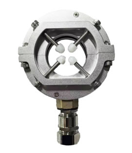
- HF CT (High Frequency Current Transformer) is a specialist sensor designed to detect partial discharge activity in medium voltage switchgear, power cables, and transformers by capturing high-frequency current pulses in the MHz range.
- Unlike conventional 50/60 Hz protection CTs, an HF CT partial discharge sensor responds to transient signals between 500 kHz and 50 MHz, enabling early-stage insulation fault detection.
- Available in split-core and solid-core configurations — split-core HF CTs allow retrofit installation on energised switchgear without shutdown.
- Installed on cable termination earth straps, busbar earth connections, or surge arrester earth leads inside medium voltage switchgear panels.
- HF CT-based monitoring delivers quantifiable partial discharge readings in picocoulombs (pC), fully compliant with IEC 60270 calibration requirements.
- This guide covers working principle, types, key specifications, installation locations, comparison with TEV sensors and UHF sensors, selection criteria, and 10 frequently asked questions.
Table of Contents
- What Is an HF CT and Why Does It Matter for Electrical Asset Protection?
- How Does a High Frequency Current Transformer Work?
- HF CT vs Conventional CT: What Is the Difference?
- What Types of HF CT Are Available?
- Key Specifications: How to Read an HF CT Datasheet?
- Where Is an HF CT Installed in Medium Voltage Switchgear?
- HF CT for Power Cable Partial Discharge Monitoring
- HF CT vs TEV Sensor vs UHF Sensor: Which PD Detection Method Should You Choose?
- Does an HF CT Need Calibration? Understanding IEC 60270 Compliance
- How to Select the Right HF CT for Your Project?
- Common Installation Mistakes and How to Avoid Them
- Frequently Asked Questions (FAQ)
1. What Is an HF CT and Why Does It Matter for Electrical Asset Protection?
![]() E-mail: web@fjinno.net
E-mail: web@fjinno.net
WhatsApp: +8613599070393
An HF CT, or High Frequency Current Transformer, is a electromagnetic sensor purpose-built to detect the weak, fast-rising current pulses generated by partial discharge (PD) activity inside electrical insulation systems. Partial discharge is a localised dielectric breakdown that does not fully bridge the gap between conductors, but left undetected, it progressively degrades insulation until complete failure occurs — often resulting in arc flash, equipment destruction, or unplanned outages.
In medium voltage networks operating at 6.6 kV, 11 kV, 22 kV, 33 kV, and above, insulation defects in switchgear, cable joints, cable terminations, and power transformers generate PD pulses with frequency content ranging from hundreds of kilohertz to tens of megahertz. A standard protection or metering CT, designed for 50 or 60 Hz power frequency, simply cannot respond to these signals. The HF CT fills this gap, acting as the front-end sensor that feeds data into a partial discharge monitoring system for continuous, real-time insulation condition assessment.
Who Uses HF CTs?
HF CTs are widely deployed by utility companies, industrial facility operators, data centre owners, rail traction power engineers, and switchgear OEMs. They form a core component of condition-based maintenance (CBM) programmes, helping organisations shift from costly time-based inspection schedules to data-driven asset management.
2. How Does a High Frequency Current Transformer Work?

Electromagnetic Induction at High Frequency
The operating principle of an HF CT is the same fundamental law of electromagnetic induction used in all current transformers: a time-varying current flowing through a conductor that passes through the CT core induces a proportional voltage across the secondary winding. The critical difference lies in the frequency response. While a conventional CT is optimised for narrowband operation at power frequency, an HF CT is engineered for wideband response, typically covering 500 kHz to 50 MHz or higher.
When a partial discharge event occurs, it generates a current pulse with a rise time measured in nanoseconds. This pulse propagates along the earthing conductor of a cable termination or busbar connection. The HF CT, clamped around that conductor, captures the pulse and converts it into a measurable output voltage proportional to the discharge magnitude.
Core Materials — Nanocrystalline vs Ferrite
The core material is what gives an HF CT its bandwidth. Two materials dominate the market. Nanocrystalline alloy cores offer excellent permeability and a broad, flat frequency response from low kHz well into the MHz range, making them ideal for quantitative PD measurement in accordance with IEC 60270. Ferrite cores provide good performance at higher MHz frequencies but may roll off at lower frequencies. The choice between them depends on the required bandwidth and the target application.
Transfer Impedance
The output of an HF CT is characterised by its transfer impedance (Zt), expressed in millivolts per milliampere (mV/mA) or ohms. A higher transfer impedance means a larger output signal for a given PD pulse current, improving the signal-to-noise ratio. Typical values range from 1 Ω to 20 Ω depending on the design.
3. HF CT vs Conventional CT: What Is the Difference?
Many engineers first encountering HF CTs ask how they differ from the protection and metering CTs already installed in every switchgear panel. The comparison below makes the distinctions clear.
| Parameter | Conventional CT (Protection / Metering) | HF CT (Partial Discharge Detection) |
|---|---|---|
| Frequency Range | 50 / 60 Hz | 500 kHz – 50 MHz |
| Primary Function | Current measurement, relay protection | Partial discharge pulse detection |
| Core Material | Grain-oriented silicon steel | Nanocrystalline alloy or ferrite |
| Output Signal | Secondary current (1 A or 5 A) | Voltage proportional to PD pulse (mV) |
| Sensitivity | Ampere-level | Picocoulomb-level (pC) |
| Installation Location | Primary conductor (busbar or cable) | Earth strap or earth conductor |
| Typical Application | Overcurrent, differential, distance protection | Online / offline PD monitoring |
The two types of CT serve entirely different purposes and are not interchangeable. An HF CT does not measure load current, and a conventional CT cannot detect partial discharge.
4. What Types of HF CT Are Available?
Split-Core (Open) HF CT — Retrofit Without Shutdown
A split-core HF CT features a hinged or two-piece core that can be opened and clamped around an existing earth conductor without disconnecting it. This makes it the preferred choice for retrofit partial discharge monitoring projects where the switchgear or cable system is already in service and a shutdown is not feasible.
Solid-Core (Closed) HF CT — Maximum Sensitivity
A solid-core HF CT has a continuous, unbroken toroidal core. Because there is no air gap at the joint, it delivers slightly better sensitivity and frequency response than a split-core equivalent. Solid-core types are typically specified for new-build switchgear and cable installations where the earth conductor can be threaded through the CT during assembly.
Rogowski Coil Type — Flexible and Lightweight
A Rogowski coil is an air-cored, flexible current sensor that can also operate in the high-frequency range. It is extremely lightweight and easy to install around irregular conductor geometries. However, because it has no magnetic core, its sensitivity is lower than cored HF CTs, and it requires an integrator circuit to produce a proportional output.
| Feature | Split-Core HF CT | Solid-Core HF CT | Rogowski Coil |
|---|---|---|---|
| Installation | Clamp-on, no disconnection | Thread-through during assembly | Wrap-around, flexible |
| Sensitivity | High | Highest | Moderate |
| Air Gap Effect | Minor sensitivity reduction | None | Not applicable |
| Best For | Retrofit projects | New-build panels | Irregular conductor shapes |
| Requires Integrator? | No | No | Yes |
5. Key Specifications: How to Read an HF CT Datasheet?
Bandwidth and Frequency Response
Look for the -3 dB bandwidth, which defines the usable frequency range. A wider bandwidth captures more of the PD pulse energy. For IEC 60270-compliant measurements, a lower cutoff below 1 MHz is generally required.
Sensitivity and Transfer Impedance
Transfer impedance (Zt) directly determines how much output voltage you get per unit of PD current. Higher Zt means better signal-to-noise performance, but excessively high values can cause saturation with large PD events. A typical range of 1–10 Ω suits most switchgear applications.
Inner Diameter, Insulation Rating and Mounting
The inner diameter must be large enough to fit around the target earth conductor. Common sizes are 20 mm, 30 mm, and 50 mm. The insulation rating should be appropriate for the installation environment. Mounting brackets or adhesive pads are used to secure the CT in position inside the panel.
6. Where Is an HF CT Installed in Medium Voltage Switchgear?
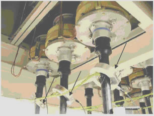
Cable Termination Earth Strap
The most common installation point is the earth strap connecting the cable screen to the switchgear earth bar at each cable termination. PD originating in the cable termination, cable joint, or cable insulation will produce current pulses flowing through this strap, directly into the HF CT.
Busbar Earth Connection
In some panel designs, an HF CT is placed on the earth connection of the busbar compartment to detect PD from busbar insulation, support insulators, or spout contacts.
Surge Arrester Earth Lead
HF CTs installed on surge arrester earth leads can simultaneously monitor arrester leakage current and capture PD activity from nearby insulation systems.
How Many HF CTs Per Panel?
A typical three-phase medium voltage panel requires three HF CTs — one per phase cable termination. Additional CTs may be added on busbar compartment earths for comprehensive coverage.
7. HF CT for Power Cable Partial Discharge Monitoring
XLPE Cable Joints and Terminations
Cross-linked polyethylene (XLPE) cables are the dominant cable technology in modern medium and high voltage networks. The most vulnerable points are the factory-made or field-assembled cable joints and cable terminations, where manufacturing defects, contamination, or improper installation can initiate partial discharge. An HF CT installed on the earth screen connection at each accessory provides continuous surveillance of these critical points.
Online vs Offline Cable PD Testing
Online PD monitoring uses permanently installed HF CTs to capture PD data while the cable operates at normal service voltage. Offline PD testing requires the cable to be de-energised and driven by an external voltage source, with a temporary HF CT connected during the test. Online monitoring provides trending and early warning capability; offline testing delivers a detailed diagnostic snapshot at a single point in time. Many asset owners combine both approaches.
8. HF CT vs TEV Sensor vs UHF Sensor: Which PD Detection Method Should You Choose?
No single PD detection technology is perfect for every situation. The table below compares the five most widely used sensor types.
| Criteria | HF CT | TEV Sensor | UHF Sensor | Ultrasonic Sensor | Capacitive Coupler |
|---|---|---|---|---|---|
| Frequency Range | 0.5–50 MHz | 3–100 MHz | 300 MHz–3 GHz | 20–100 kHz (acoustic) | Wideband (varies) |
| Measurand | Current pulse | Surface voltage | EM radiation | Sound pressure | Voltage pulse |
| pC Quantification (IEC 60270) | Yes | No | No (correlation only) | No | Yes |
| Sensitivity | Very high | Moderate | High | Moderate | High |
| Installation Complexity | Easy (clamp-on) | Very easy (magnetic) | Moderate (internal antenna) | Easy (external) | Moderate |
| Best Application | Switchgear & cable PD | Metal-clad switchgear screening | GIS & transformer PD | Locating PD source | Cable PD testing |
| Online Monitoring Capable? | Yes | Yes | Yes | Limited | Yes |
Can You Combine Multiple PD Sensors?
Yes. Best practice in many utility and industrial partial discharge monitoring systems is to deploy a combination of HF CTs and TEV sensors — or HF CTs and UHF sensors — to improve detection confidence, enable cross-verification, and assist with PD source localisation. The multi-sensor approach is recommended by CIGRE and endorsed in numerous technical brochures.
9. Does an HF CT Need Calibration? Understanding IEC 60270 Compliance
Factory Calibration vs Field Verification
Every HF CT should be supplied with a factory calibration certificate documenting its transfer impedance across the rated bandwidth. This calibration links the sensor output voltage to the actual PD charge in picocoulombs, which is essential for trending, alarm setting, and compliance reporting. Field verification using a known PD calibrator injected at the cable termination confirms the entire measurement chain — sensor, cable, and acquisition unit — is functioning correctly.
Traceability and pC Quantification
IEC 60270 is the international standard for partial discharge measurement. It requires that the measurement system be calibrated in picocoulombs with traceable uncertainty. An HF CT with a documented, flat transfer impedance within the measurement bandwidth enables direct pC quantification, which is the single greatest technical advantage of HF CT-based PD monitoring over non-quantitative methods such as TEV or ultrasonic sensing.
10. How to Select the Right HF CT for Your Project?
Matching CT Inner Diameter to Earth Conductor Size
Measure the cross-section of the earth strap or earth conductor at the intended installation point. Choose an HF CT with an inner diameter that allows easy clamping with minimal air gap. An oversized CT reduces coupling efficiency; an undersized CT simply will not fit.
Shielding, Cable Routing and Noise Rejection
HF signals are susceptible to electromagnetic interference. Use double-shielded coaxial signal cables between the HF CT and the data acquisition unit. Keep signal cables as short as possible and route them away from power conductors and variable-speed drives.
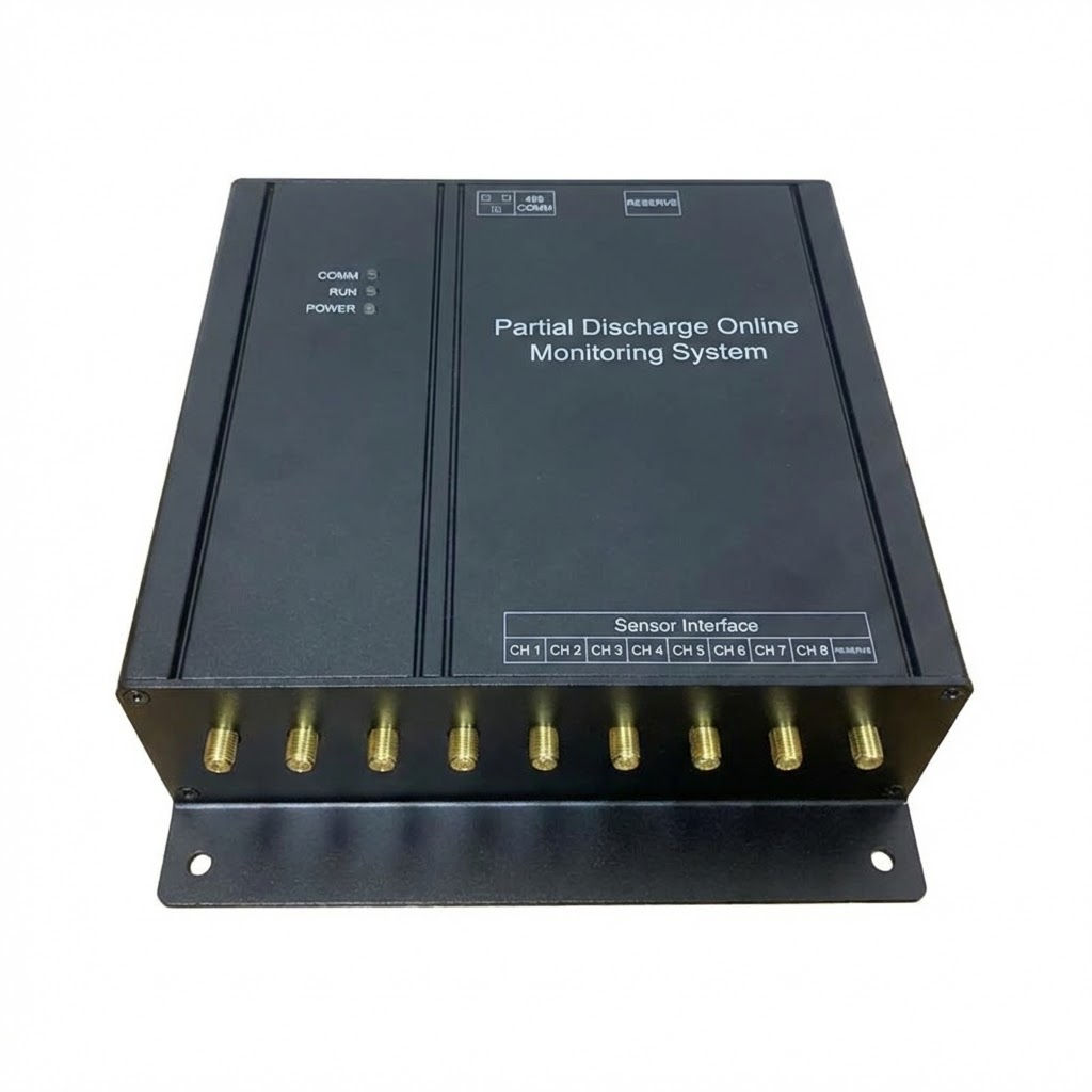
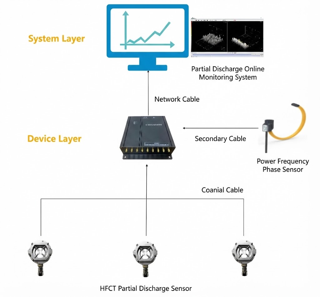
Integration with Online PD Monitoring Systems
Ensure the HF CT output impedance is compatible with your chosen PD monitoring system input. Most systems accept 50 Ω BNC connections. Confirm the system supports the CT bandwidth and provides trending, alarm management, and communication via Modbus RTU, IEC 61850, or Ethernet TCP/IP for SCADA integration.
11. Common Installation Mistakes and How to Avoid Them
Mistake 1: Installing on the wrong conductor
The HF CT must be placed on the earth screen conductor, not on the main power cable. Installing it on the phase conductor exposes the sensor to dangerously high power-frequency current and will not yield valid PD data.
Mistake 2: Leaving excessive air gap in split-core types
If a split-core CT is not fully closed, the air gap dramatically reduces sensitivity. Always check the latch mechanism and ensure the core halves are firmly mated.
Mistake 3: Using unshielded signal cables
Running unshielded cables inside a switchgear panel filled with electromagnetic noise will overwhelm the weak PD signal. Always use quality shielded coaxial cable and proper BNC connectors.
Mistake 4: Ignoring cable length limits
Long signal cable runs attenuate high-frequency signals. Consult the HF CT manufacturer’s guidelines for maximum cable length and use low-loss coaxial cable if extended runs are unavoidable.
Mistake 5: No calibration verification after installation
A sensor that is installed but never verified against a known calibrator cannot produce trustworthy data. Always perform a site calibration check using a PD calibrator injected at the cable termination.
12. Frequently Asked Questions (FAQ)
Q1: What does HF CT stand for?
HF CT stands for High Frequency Current Transformer. It is a sensor designed to detect high-frequency current pulses generated by partial discharge activity in electrical insulation.
Q2: What frequency range does an HF CT cover?
Most HF CTs cover a bandwidth from approximately 500 kHz to 50 MHz. Some specialised designs extend down to 100 kHz or up to 80 MHz depending on the core material and winding design.
Q3: Can an HF CT be installed without shutting down the switchgear?
Yes. A split-core (clamp-on) HF CT can be installed on the earth conductor while the switchgear remains energised, provided safe working practices and appropriate personal protective equipment are observed.
Q4: What is the difference between an HF CT and a Rogowski coil?
An HF CT uses a magnetic core (nanocrystalline or ferrite) and delivers high sensitivity without an external integrator. A Rogowski coil is air-cored and flexible but has lower sensitivity and requires an integrator to convert its di/dt output into a proportional signal.
Q5: How sensitive is an HF CT for partial discharge detection?
A well-designed HF CT can detect PD levels below 5 pC in a typical switchgear environment, which is well within the threshold needed for early-stage insulation defect identification.
Q6: Is an HF CT suitable for low voltage switchgear?
HF CTs are primarily designed for medium and high voltage applications where partial discharge is a recognised insulation degradation mechanism. In low voltage systems, partial discharge is rarely the dominant failure mode, so HF CTs are not commonly deployed at LV level.
Q7: How many HF CTs are needed per switchgear panel?
A standard three-phase cable-connected panel typically requires three HF CTs, one on each phase earth strap. Additional CTs may be added on busbar compartment earths or surge arrester leads depending on the monitoring strategy.
Q8: What is transfer impedance in an HF CT?
Transfer impedance (Zt) is the ratio of the output voltage to the input current at a given frequency, expressed in ohms or mV/mA. It defines the sensor’s conversion efficiency and directly affects the signal-to-noise ratio of the PD measurement.
Q9: Can an HF CT measure partial discharge in picocoulombs (pC)?
Yes. When properly calibrated according to IEC 60270, an HF CT-based measurement system can quantify partial discharge amplitude in picocoulombs, enabling trending, severity assessment, and standards-compliant reporting.
Q10: What standards apply to HF CT-based partial discharge monitoring?
The primary standard is IEC 60270 (Partial Discharge Measurements). Related standards include IEC 62271-200 (metal-enclosed switchgear), IEEE C57.127 (transformer PD detection), and various CIGRE Technical Brochures on PD monitoring best practices.
Disclaimer: The information provided in this article is for general educational and reference purposes only. It does not constitute professional engineering advice. While every effort has been made to ensure accuracy, www.fjinno.net assumes no liability for any errors, omissions, or consequences arising from the use of this information. Always consult qualified electrical engineers and follow applicable local codes, standards, and safety regulations when specifying, installing, or operating HF CTs and partial discharge monitoring equipment. Product specifications and performance data mentioned herein are representative and may vary by manufacturer.

Fiber optic temperature sensor, Intelligent monitoring system, Distributed fiber optic manufacturer in China
 |
 |
 |