 INNO fibre optic temperature sensors ,temperature monitoring systems.

A major power facility utilizes high-voltage dry type transformers as core power supply equipment. Since dry type transformers rely on air convection for cooling, accurate monitoring of winding hot spot temperatures proved challenging. Traditional PT100 sensors cannot directly contact high-voltage windings, creating temperature measurement blind spots and potential safety risks.
Our Solution
We deployed a Fiber Optic Temperature Monitoring System to achieve precise temperature control through the following implementation:
Installation Process
- Fiber optic temperature sensors embedded directly into transformer winding hot spot areas
- Precise positioning of fiber probes at locations most prone to high temperatures
- Professional cable routing ensuring no interference with transformer heat dissipation
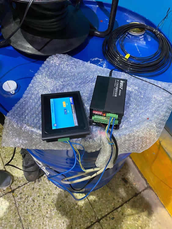
- Connection to intelligent temperature monitoring device for real-time data acquisition
Technical Features
- Intrinsically Safe: Fiber optic material provides electrical insulation, enabling direct contact with high-voltage windings
- Superior EMI Immunity: Unaffected by transformer’s strong electromagnetic fields
- High Measurement Accuracy: Direct hot spot temperature measurement with ±1℃ precision
- Long-term Stability: Heat resistant up to 180℃ with service life exceeding 20 years
Results & Benefits
The system has delivered remarkable outcomes since commissioning:
- Real-time Monitoring: 24/7 continuous winding hot spot temperature monitoring with per-second data updates
- Early Warning: Automatic alarms for temperature anomalies, detecting potential failures 48 hours in advance
- Intelligent Control: Automatic fan start/stop based on temperature, achieving 15% energy savings
- Extended Lifespan: Precise temperature control prevents overheating and aging, extending equipment life by 30%
- Zero Downtime: No unplanned outages due to temperature issues in the first year of operation
Customer Testimonial
“The fiber optic temperature monitoring system enables us to directly monitor transformer winding hot spots for the first time. Temperature data is accurate and reliable. The system installation was straightforward, operation is stable, significantly improving our equipment management and power supply reliability. This has been a highly successful technical upgrade.”
— Project Manager
Performance Comparison
| Metric | Traditional PT100 | Fiber Optic System |
|---|---|---|
| Measurement Location | Winding surface/enclosure | Internal winding hot spot |
| Measurement Accuracy | ±2-3℃ | ±1℃ |
| EMI Immunity | Susceptible to EMI | Complete immunity |
| High Voltage Insulation | Requires complex insulation treatment | Natural insulation |
| Response Speed | 3-5 minutes | <10 seconds |
| Service Life | 5-8 years | 20+ years |
Installation Gallery
Step 1: Cable Routing
Fiber optic cables are carefully routed into the transformer winding area, ensuring optimal positioning for accurate temperature measurement.
Step 2: Sensor Positioning
Temperature sensors are precisely installed at critical hot spot locations within the epoxy-cast windings.
Step 3: Probe Fixation
Fiber optic probes are securely mounted using specialized fixtures to ensure long-term stability and reliable contact with winding surfaces.
Step 4: System Integration
All sensors are connected to the central monitoring unit, enabling comprehensive real-time temperature tracking across all critical points.
Key Technical Specifications
System Components
- Fiber Optic Sensors: Fluorescence-based temperature measurement technology
- Temperature Range: -40℃ to 180℃
- Measurement Channels: Up to 16 channels per monitoring device
- Communication Protocol: Modbus RTU/TCP, SCADA compatible
- Power Supply: AC 220V ±10% or DC 110V/220V
- Protection Rating: IP54 (monitoring device enclosure)
Alarm Functions
- Multi-level temperature alarms (warning, over-temperature, trip)
- Temperature rise rate monitoring
- Sensor fault detection
- Historical data logging and analysis
- Remote notification via email/SMS
Application Industries
This fiber optic temperature monitoring solution is ideal for:
- Power Generation Plants: Generator step-up transformers and auxiliary transformers
- Rail Transit Systems: Traction transformers in metro and light rail networks
- Wind & Solar Farms: Renewable energy converter transformers
- Industrial Facilities: Manufacturing plants and processing facilities
- Data Centers: UPS and power distribution transformers
- Commercial Buildings: High-rise building electrical systems
Why Choose Fiber Optic Monitoring?
Advantages Over Traditional Methods
Direct Hot Spot Measurement: Unlike PT100 sensors that measure external temperatures, fiber optic sensors can be embedded directly into windings for true hot spot monitoring.
No Electrical Interference: Being non-conductive, fiber optic sensors eliminate concerns about electrical breakdown, grounding issues, or signal interference in high-voltage environments.
Explosion-Proof Design: With no electrical components at the sensing point, fiber optic systems are intrinsically safe for use in hazardous locations.
Lightning Protection: Non-metallic fiber optic cables are immune to lightning strikes and electrical surges that can damage conventional wiring.
Maintenance-Free Operation: Solid-state sensing technology with no moving parts ensures decades of reliable operation without calibration or replacement.
Investment Return Analysis
Cost Savings
- Avoided Downtime: Preventing one transformer failure saves $50,000-$500,000 in emergency repairs and lost revenue
- Extended Equipment Life: 30% life extension on a $200,000 transformer equals $60,000 in deferred capital costs
- Energy Optimization: 15% cooling energy savings translates to $3,000-$8,000 annually for medium-sized installations
- Insurance Benefits: Proactive monitoring may qualify for reduced insurance premiums
Typical Payback Period
Based on average installation costs and documented benefits, most customers achieve full ROI within 18-24 months of system deployment.
Compliance & Certifications
- IEC 60076 – Power Transformers Standard
- IEEE C57.12.01 – Dry-Type Transformers Standard
- CE Certification – European Conformity
- Railway Certification – EN 50155 (for rail transit applications)
- ATEX/IECEx – Explosion-proof certification (optional)
- ISO 9001 – Quality Management System
Next Steps
Interested in implementing a fiber optic temperature monitoring solution for your dry type transformers? Our team of experts is ready to:
- Conduct a free site assessment of your transformer installation
- Design a customized monitoring solution based on your specific requirements
- Provide detailed technical specifications and system layout drawings
- Offer competitive pricing with flexible payment terms
- Deliver comprehensive training and ongoing technical support
Contact Us Today
Transform your transformer monitoring capabilities with proven fiber optic technology. Contact our sales team to discuss your project requirements and receive a customized proposal within 48 hours.
Available Support:
- 24/7 Technical Hotline
- Remote Commissioning Assistance
- On-site Installation Supervision
- Comprehensive Documentation Package
- Lifetime Technical Support

Fiber optic temperature sensor, Intelligent monitoring system, Distributed fiber optic manufacturer in China
 |
 |
 |


 hybrid insulated oil transformers in substations")


