 INNO fibre optic temperature sensors ,temperature monitoring systems.
- Fluorescent fiber optic sensors provide ±1°C accuracy for real-time switchgear hotspot detection across contacts, busbars, and cable terminations
- Complete electromagnetic immunity makes fiber optic temperature monitoring the optimal solution for high-voltage environments where traditional sensors fail
- Multi-channel systems (1-64 points) enable comprehensive monitoring of MV/HV switchgear, ring main units, rectifier cabinets, and GIS installations
- Over 20-year maintenance-free operation with no calibration requirements reduces total cost of ownership for critical electrical infrastructure
- Global installations across substations, industrial facilities, data centers, and mining operations demonstrate proven reliability in extreme conditions
- CE, RoHS certified with optional UL and ATEX explosion-proof certifications for demanding applications
Table of Contents
1. What is Fluorescent Fiber Optic Switchgear Temperature Monitoring?

Fluorescent fiber optic temperature monitoring represents the most advanced technology for detecting thermal hotspots in electrical switchgear. The system uses rare-earth doped crystal sensors that emit temperature-dependent fluorescent signals transmitted through optical fibers to a central processor.
Switchgear contact and busbar connections generate heat during operation. Poor contact resistance, loose connections, or overloading create dangerous hotspots that traditional monitoring methods struggle to detect reliably in high-voltage electromagnetic environments.
Fiber optic temperature sensors solve these challenges by using light signals instead of electrical measurements, providing complete immunity to electromagnetic interference while maintaining intrinsic safety in explosive atmospheres. The technology delivers accurate real-time data enabling predictive maintenance and preventing catastrophic failures in critical electrical infrastructure.
2. Why Does Switchgear Need Temperature Monitoring?

Fire Risk Prevention
Electrical fires originating from switchgear cause significant property damage and safety hazards. Temperature monitoring detects abnormal heating before ignition occurs, providing early warning that enables intervention.
Contact Deterioration Detection
Moving and stationary contacts in circuit breakers and disconnect switches experience mechanical wear and oxidation that increases resistance and generates heat. Continuous monitoring identifies deteriorating contacts requiring maintenance.
Busbar Connection Integrity
Bolted busbar joints loosen due to thermal cycling and vibration. Increased contact resistance at these connections produces localized heating that fiber optic temperature measurement systems detect immediately.
Load Capacity Management
Accurate temperature data allows operators to safely maximize switchgear loading during peak demand while maintaining thermal limits, optimizing infrastructure utilization without risking damage.
3. What Are Common Switchgear Overheating Faults?

Moving and Stationary Contact Resistance
Contact surface oxidation, pitting, and contamination increase electrical resistance. Under load, increased resistance generates excessive heat that accelerates further degradation.
Loose Busbar Bolt Connections
Thermal expansion, contraction cycles, and mechanical vibration cause bolted connections to loosen over time. Poor contact generates significant heat under normal operating current.
Isolator Switch Contact Finger Pressure Loss
Spring-loaded contact fingers in disconnect switches lose mechanical pressure through fatigue, reducing contact area and increasing resistance.
Cable Termination Crimping Issues
Improperly crimped or compressed cable lugs create high-resistance connections that produce substantial heating under load conditions.
Insulation Aging and Partial Discharge
Deteriorating insulation materials develop partial discharge activity that generates localized heating. Fluorescent temperature sensors detect these thermal signatures early.
Harmonic Current Additional Losses
Non-linear loads generate harmonic currents that increase resistive losses in conductors and connections, creating hotspots that monitoring systems identify.
Ambient Temperature Impact
High ambient temperatures reduce heat dissipation capacity. Temperature monitoring ensures switchgear operates within safe limits despite environmental conditions.
4. What Types of Temperature Sensors Work in Switchgear?

Traditional Thermocouple Limitations
Thermocouples generate millivolt signals vulnerable to electromagnetic interference from high-voltage equipment, producing unreliable readings in switchgear environments.
PT100 RTD Electromagnetic Interference
Platinum resistance thermometers require electrical excitation and measurement circuits susceptible to EMI, limiting accuracy in switchgear applications.
Infrared Thermography Obstruction Issues
Infrared cameras require direct line-of-sight to measurement points. Enclosed switchgear designs prevent continuous infrared monitoring of internal components.
Wireless Temperature Sensor Challenges
Battery-powered wireless sensors have limited lifespan and signal penetration issues through metal enclosures. Maintenance requirements for battery replacement increase operational costs.
Fluorescent Fiber Optic Sensor Advantages
Fluorescent fiber optic temperature measurement eliminates all electrical interference issues while providing superior accuracy and maintenance-free operation over 20+ year service life.
Distributed vs Point Sensing Comparison
Distributed fiber optic sensing (DTS) measures along fiber lengths but offers lower accuracy and slower response than point sensors. Fluorescent point sensors provide ±1°C accuracy with under 5-second response times.
5. How Does Fluorescent Temperature Sensor Work?
Rare-Earth Fluorescent Material Response
A rare-earth doped crystal at the fiber optic sensor tip absorbs excitation light pulses and emits fluorescent light. The fluorescence decay time changes predictably with temperature based on fundamental quantum properties.
Optical Signal Transmission
Excitation pulses travel through the optical fiber to the sensor probe. Returning fluorescent signals carry temperature information back through the same fiber to the measurement processor.
Multi-Channel Time-Division Multiplexing
Fiber optic temperature monitoring systems can multiplex up to 64 individual sensors using time-division techniques, with each measurement point connected via dedicated fiber to a central unit.
Calibration-Free Operation
Fluorescence decay time depends on invariant physical properties of the phosphor material. These quantum mechanical characteristics remain absolutely stable over decades, eliminating field calibration requirements entirely.
6. Why Choose Fluorescent Technology for Switchgear Monitoring?
High Measurement Accuracy
Fluorescent temperature sensors deliver ±1°C accuracy across the complete operating range, exceeding requirements for switchgear thermal management and protection.
Complete EMI Immunity
As purely optical devices, fluorescent sensors experience zero interference from electrical fields, magnetic fields, or high-voltage transients present in substations and industrial facilities.
Intrinsic Safety Certification
With no electrical components at measurement points, fluorescent sensors cannot create sparks or ignition sources. Systems meet ATEX and IECEx explosion-proof standards for hazardous locations.
Extended Service Life
The fundamental physics of fluorescence ensures measurement stability exceeding 20 years. Installations from 2011 continue operating with original factory calibration accuracy.
Flexible Multi-Channel Configuration
Fiber optic switchgear monitoring systems accommodate 1 to 64 temperature measurement points, enabling comprehensive coverage from small ring main units to large GIS installations.
Wide Temperature Range
Operating range from -40°C to +260°C covers all switchgear applications from outdoor installations in extreme climates to high-temperature rectifier and furnace applications.
Certified Quality Standards
Systems carry CE and RoHS certification as standard. UL certification and ATEX explosion-proof ratings available for applications requiring these specific approvals.
7. How to Monitor Different Types of Switchgear?
7.1 Fixed Switchgear and GIS
Isolator Contact Temperature Monitoring
Gas-insulated switchgear (GIS) isolator contacts operate in SF6 environment. Fluorescent fiber optic sensors install directly on contact assemblies, with fibers penetrating sealed compartments through special feedthroughs.
Busbar Connection Point Installation
Sensors mount at bolted busbar joints using specialized clamps or integrated during assembly. Optical fibers route through cable ducts to monitoring equipment.
Cable Termination Monitoring
Sensor probes attach to cable lugs and termination blocks, detecting poor crimping or connection degradation before failure occurs.
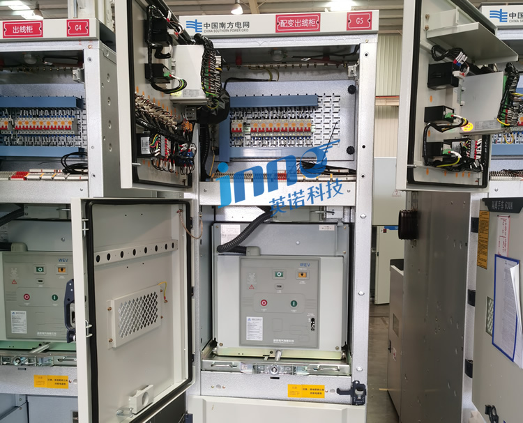
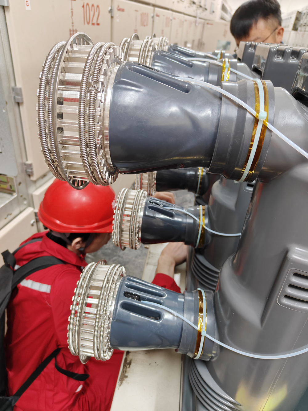
7.2 Withdrawable (Draw-out) Circuit Breaker Switchgear
Fixed Contact Assembly Temperature
Stationary contacts in the switchgear housing require permanent sensor installation. Temperature monitoring systems track contact condition despite breaker insertion and withdrawal.
Moving Contact Interface Measurement
While moving contacts on breaker trucks cannot have permanently installed sensors, stationary contact monitoring detects interface heating caused by poor engagement.
Secondary Plug Connection Monitoring
Control circuit connector blocks benefit from temperature monitoring in critical applications where connection reliability affects protection system operation.
7.3 Ring Main Units
Load Break Switch Contact Temperature
Compact ring main unit designs concentrate heat in small volumes. Fiber optic temperature sensors provide critical monitoring in these space-constrained applications.
Cable T-Connection Monitoring
Ring feed-through connections experience full load current continuously. Temperature monitoring ensures connection integrity in these critical points.
Ring Busbar Joint Measurement
Circular busbar connection points in ring main units require careful temperature monitoring due to limited heat dissipation capacity.
7.4 SF6 Gas-Insulated Switchgear
SF6 Environment Temperature Monitoring
Fluorescent temperature measurement systems operate reliably in SF6 gas without affecting gas properties or introducing contamination.
Sealed Compartment Internal Sensing
Sensor probes install inside pressurized compartments during manufacturing or major maintenance, providing continuous monitoring without compromising gas sealing.
Fiber Penetration Sealing Solutions
Specialized fiber optic feedthroughs maintain pressure integrity while allowing optical signal transmission to external monitoring equipment.
7.5 Rectifier Switchgear
Harmonic Current Heating Effects
Rectifier loads generate significant harmonic currents that increase conductor and connection losses. Fiber optic temperature monitoring tracks these additional thermal stresses.
DC Busbar Connection Monitoring
DC-side busbar connections in rectifier switchgear experience unique thermal characteristics requiring dedicated monitoring.
Thyristor and Diode Junction Temperature
Power semiconductor junction temperatures affect reliability and performance. Fluorescent sensors provide accurate thermal data for protection and optimization.
8. Which Switchgear Points Need Temperature Monitoring?
Incoming Feeder Switchgear
Line-side terminals and main busbar connections carry full substation load. These critical points require priority monitoring with fiber optic temperature sensors.
Outgoing Feeder Switchgear
Circuit breaker contacts, load-side terminals, and cable connection lugs need monitoring to detect deterioration before service interruption occurs.
Bus Coupler Switchgear
Bus coupler breaker contacts and busbar bridge connections carry variable loading during normal splitting and emergency transfer operations, justifying temperature monitoring.
Metering Switchgear
Current transformer and voltage transformer terminal connections benefit from monitoring in revenue metering applications where failures affect billing accuracy.
Voltage Transformer Switchgear
PT/VT primary winding terminals and fuse holders require monitoring in critical protection and control applications.
Universal Busbar Connections
Bolted busbar joints, isolation switch blades, and sliding contacts throughout all switchgear sections represent potential failure points requiring temperature measurement.
9. What Voltage Levels Need Temperature Monitoring?
9.1 High Voltage Switchgear (10kV-35kV)
Substation Outgoing Feeders
Distribution substations supplying urban and industrial networks justify comprehensive fiber optic temperature monitoring due to high consequence of failure.
Industrial Enterprise Distribution Rooms
Manufacturing facilities with dedicated substations require monitoring to prevent production losses from switchgear failures.
Commercial Complex Power Distribution
Large commercial buildings, shopping centers, and office complexes benefit from monitoring systems preventing service interruptions.
9.2 Medium Voltage Switchgear (6kV-10kV)
Factory Power Distribution
Industrial motor control centers and distribution switchgear serving critical production equipment warrant temperature monitoring systems.
Mining Power Supply Systems
Underground and surface mining electrical installations operate in harsh environments where monitoring prevents costly unplanned outages.
Port and Dock Electrical Distribution
Container terminal and port facility switchgear serves critical cargo handling equipment requiring high reliability.
9.3 Low Voltage Switchgear (380V-690V)
Data Center Distribution Panels
Mission-critical data centers implement comprehensive fiber optic monitoring on all power distribution equipment to achieve tier III/IV availability requirements.
Hospital Operating Room Power Supply
Life-safety electrical systems in healthcare facilities require monitoring to ensure continuous operation during surgical procedures.
Critical Production Line Distribution
Process industries with expensive downtime costs justify monitoring even on low-voltage distribution equipment feeding essential loads.
10. How Many Monitoring Points Does Switchgear Need?
Compact Ring Main Units
Small ring main units typically require 3-6 temperature sensors covering load break switch contacts, cable connections, and busbar joints.
Standard Incoming/Outgoing Panels
Conventional switchgear panels use 6-9 measurement points monitoring breaker contacts, busbar connections, and cable terminations across three phases.
Double Busbar Systems
Switchgear with bus sectionalizing requires 9-12 sensors covering both busbar systems, coupler connections, and isolation points.
Large GIS Installations
Gas-insulated substations implement 12-32 channel fiber optic temperature monitoring providing comprehensive coverage of all compartments and connections.
Load Criticality Considerations
Essential service switchgear warrants more extensive monitoring regardless of size, while redundant systems in networks with alternative supply may use fewer sensors.
11. How Does Temperature Monitoring Prevent Switchgear Faults?
11.1 Temperature Alarm Threshold Configuration
Pre-Warning Temperature Levels
First-stage alarms trigger at ambient +40°C, alerting operators to elevated conditions requiring attention during next scheduled maintenance.
Warning Temperature Levels
Second-stage alarms at absolute temperatures of 75-85°C indicate need for investigation and potential load reduction or accelerated maintenance.
Emergency Trip Temperature
Critical alarms at 90-100°C provide automatic protection, removing switchgear from service before insulation damage or contact welding occurs.
Rate-of-Rise Alarms
Temperature monitoring systems trigger alarms when sensors detect temperature increases exceeding 5°C in 10 minutes, indicating developing faults even below absolute limits.
11.2 Fault Types Detected Through Temperature
Contact Resistance Anomalies
Gradually increasing temperature at contact points under constant load indicates progressive oxidation or wear requiring attention.
Bolt Loosening
Temperature fluctuations correlating with load changes suggest loose connections that tighten and loosen with thermal cycling.
Contact Wear Progression
Slowly rising temperature trends over months indicate cumulative wear of breaker and switch contacts approaching maintenance requirements.
Overload Operation
Simultaneous temperature increases across all three phases indicate loading exceeding switchgear ratings, enabling load management intervention.
Phase Imbalance Detection
One phase showing abnormal temperature while others remain normal indicates unbalanced loading or single-phase connection problems requiring investigation.
11.3 Temperature Data Maintenance Applications
Trend Analysis for Degradation
Long-term temperature trending reveals gradual deterioration patterns, enabling predictive maintenance scheduling before failures occur.
Infrared Thermography Correlation
Fiber optic temperature measurement data validates periodic infrared surveys, providing continuous monitoring between scheduled thermographic inspections.
Maintenance Planning Optimization
Condition-based maintenance scheduling using temperature trends reduces unnecessary inspections while ensuring critical interventions occur at optimal times.
Equipment Health Assessment
Temperature history provides objective data for asset health scoring, supporting capital planning and replacement decision-making.
12. How to Integrate Temperature Monitoring Systems?
12.1 Integration with Existing Control Systems
Substation Automation System Connection
IEC 61850 protocol support enables direct integration with modern substation automation platforms, providing seamless temperature data incorporation into SCADA.
SCADA Platform Integration
Modbus RTU/TCP and DNP3 protocols allow fiber optic monitoring systems to connect with legacy and current SCADA implementations.
Analog and Digital Outputs
4-20mA analog outputs and programmable relay contacts provide simple integration with conventional protection and control schemes.
Network Connectivity
Ethernet interfaces support remote monitoring through secure connections, enabling expert analysis from engineering centers.
12.2 Control System Interlocking Functions
Automatic Cooling Activation
Temperature thresholds trigger forced ventilation systems, maintaining thermal limits during peak loading periods.
Load Shedding Integration
Warning temperature levels initiate automatic load reduction through SCADA commands, protecting equipment while maintaining essential services.
Emergency Trip Logic
Critical temperature conditions provide hardwired trip signals to protection relays, ensuring equipment isolation regardless of communication system status.
Mobile Alert Notifications
Temperature monitoring systems send SMS messages and push notifications to maintenance personnel for immediate response to abnormal conditions.
13. Installation Requirements
Sensor Mounting Locations
Contact monitoring requires sensor probes positioned within millimeters of stationary contacts. Busbar sensors attach using specialized clamps or cable ties at bolted joints. Cable termination sensors install on lugs using compression fittings.
Fiber Optic Cable Routing
Optical fibers route through switchgear cable ducts and trays, maintaining minimum bend radius of 25-50mm. Fibers exit panels through sealed cable glands maintaining IP protection ratings.
De-Energization Requirements
All sensor installation requires complete switchgear de-energization. Work permits, lockout/tagout procedures, and verification of zero voltage must be completed before beginning installation work. Only qualified electrical personnel should perform installations following local electrical safety codes and manufacturer specifications.
14. Real-World Application Case Studies
14.1 Middle East: 220kV Substation 10kV Switchgear Monitoring
A major substation in Saudi Arabia experienced repeated circuit breaker trips during summer months when ambient temperatures exceeded 50°C. Conventional temperature indicators provided inadequate hotspot detection.
A 32-channel fluorescent fiber optic temperature monitoring system installed in 2018 provided accurate real-time data on all critical connection points. The system identified three loose busbar connections and one circuit breaker with worn contacts before failures occurred.
Since installation, the substation has operated without temperature-related incidents. Maintenance teams use trending data to schedule repairs during planned outages, eliminating emergency interventions.
14.2 Southeast Asia: 35kV Industrial Park Distribution
A Malaysian industrial complex operates in tropical climate with high humidity and frequent electrical storms. Moisture ingress and condensation caused switchgear failures averaging twice per year.
An 18-channel fiber optic monitoring system installed in 2019 tracks temperature across all incoming and outgoing feeders. The system detected abnormal heating patterns indicating developing insulation problems, enabling four preventive interventions.
The facility has achieved zero unplanned outages in six years of operation with the monitoring system, significantly improving manufacturing uptime and reducing maintenance costs.
14.3 Africa: 6kV Mining Mobile Substation
An open-pit copper mine in Zambia operates mobile switchgear serving excavation equipment. Extreme dust, vibration, and load fluctuations caused frequent contact failures and connection problems.
A 24-channel fluorescent temperature sensor system with wireless data transmission installed in 2020 monitors all breaker contacts and cable connections. Remote monitoring enables condition assessment without site visits in the harsh environment.
Early detection of contact heating prevented multiple failures that would have caused production stoppages exceeding $200,000 per incident. The system paid for itself within six months of operation.
14.4 Data Center: Low Voltage Distribution Panel Monitoring
A Tier IV data center in Singapore requires 99.995% electrical system availability. Even brief power interruptions cause significant financial losses and service level agreement violations.
A 64-channel precision fiber optic temperature monitoring system installed in 2017 provides 0.5°C accuracy across all low-voltage distribution panels. Comprehensive monitoring enables predictive maintenance preventing failures.
The facility has operated five years without any temperature-related electrical faults, maintaining industry-leading uptime performance and avoiding millions in potential downtime costs.
15. Key Performance Specifications
Measurement Accuracy: ±1°C across full operating range
Temperature Range: -40°C to +260°C (all switchgear applications)
Response Time: Under 5 seconds for rapid fault detection
Channel Capacity: 1 to 64 independent measurement points
Sensor Lifespan: Over 20 years maintenance-free operation
Calibration: Factory calibrated, no field recalibration required
EMI Immunity: Complete immunity to all electromagnetic interference
Insulation Rating: >100kV dielectric strength
Protection Rating: IP65 (monitoring unit)
Operating Temperature: -20°C to +70°C (monitoring unit)
Certifications: CE, RoHS (standard); UL, ATEX (available)
16. Frequently Asked Questions
What is the expected lifespan of fluorescent fiber optic sensors?
Fluorescent temperature sensors maintain measurement accuracy for over 20 years without performance degradation. Installations from 2011 continue operating with original factory calibration, demonstrating exceptional long-term reliability.
Why do fluorescent sensors not require periodic calibration?
Fluorescence decay time depends on fundamental quantum mechanical properties of rare-earth materials that remain absolutely constant over time. Unlike electronic sensors that experience component aging, fluorescent sensors maintain calibration indefinitely.
Must switchgear be de-energized for sensor installation?
Yes, safe installation requires complete de-energization. Sensors install on or near energized conductors, making live work extremely dangerous. Installation occurs during scheduled maintenance outages with proper lockout/tagout procedures.
How should temperature alarm thresholds be configured?
Typical settings include pre-warning at ambient +40°C, warning alarm at 75-85°C absolute, and emergency trip at 90-100°C. Specific thresholds depend on switchgear ratings and insulation class. Consult manufacturer specifications for optimal settings.
What monitoring point quantity do different switchgear types need?
Ring main units typically use 3-6 channels. Standard distribution panels require 6-9 channels. Double-busbar systems need 9-12 channels. Large GIS installations implement 12-32 channels. Critical applications warrant more extensive monitoring regardless of size.
How does accuracy compare to platinum RTDs?
Fluorescent fiber optic sensors provide ±1°C accuracy matching Class A PT100 RTDs. Unlike RTDs, fluorescent sensors maintain accuracy indefinitely without drift and experience zero electromagnetic interference in high-voltage environments.
Are fluorescent sensors suitable for all switchgear types?
Yes, fluorescent temperature measurement works in air-insulated, gas-insulated, vacuum, oil-filled, and all other switchgear configurations. The wide temperature range covers applications from outdoor installations in extreme climates to high-temperature industrial applications.
How do systems perform in harsh industrial environments?
Installations in desert heat (+50°C), arctic cold (-40°C), tropical humidity, offshore salt spray, and mining dust demonstrate excellent reliability. The all-optical design eliminates environmental sensitivity issues affecting electrical sensors.
What certifications are available for specialized applications?
Systems carry CE and RoHS certification as standard. UL certification available for North American installations. ATEX and IECEx explosion-proof certifications available for hazardous location applications in oil/gas and chemical facilities.
Can monitoring systems integrate with existing SCADA infrastructure?
Yes, standard protocols including Modbus RTU/TCP, DNP3, and IEC 61850 enable direct integration with substation automation and industrial control systems. Analog outputs and relay contacts provide compatibility with conventional protection schemes.
17. Contact for Expert Consultation
For comprehensive information about fluorescent fiber optic switchgear monitoring systems, our technical specialists provide complete support:
- Complimentary technical consultation and customized monitoring system design
- Detailed product specifications, technical documentation, and project quotations
- Application engineering support for new installations and retrofit projects
- Professional training programs and technical documentation
Manufacturer: Fuzhou Innovation Electronic Scie&Tech Co., Ltd.
Established: 2011
Email: web@fjinno.net
WhatsApp/WeChat/Phone: +86-13599070393
Address: Liandong U Grain Networking Industrial Park, No.12 Xingye West Road, Fuzhou, Fujian, China
Website: www.fjinno.net
18. Disclaimer
Technical information and specifications provided in this guide serve reference purposes only. Specific monitoring solutions must be designed based on actual switchgear operating conditions, environmental factors, and application requirements.
Sensor installation and system integration must follow manufacturer technical specifications, local electrical codes, and industry safety standards. All installation work must be performed during scheduled outages by qualified electrical personnel with appropriate training, certification, and authorization.
Performance specifications represent typical values under normal operating conditions. Actual performance should be verified through factory acceptance testing and field commissioning. Applications in extreme environments or specialized switchgear may require customized engineering solutions.
This guide does not constitute complete engineering specifications for procurement or installation. Consult with qualified electrical monitoring specialists and follow all applicable safety codes, standards, and regulations in your jurisdiction. Fuzhou Innovation Electronic Scie&Tech Co., Ltd. assumes no liability for improper application or installation of monitoring equipment.

Fiber optic temperature sensor, Intelligent monitoring system, Distributed fiber optic manufacturer in China
 |
 |
 |