 INNO fibre optic temperature sensors ,temperature monitoring systems.
- Fiber optic temperature monitoring systems prevent equipment failures through real-time thermal surveillance of critical power generation assets
- Fluorescent fiber optic technology offers electromagnetic immunity, ±1°C accuracy, and >100kV voltage withstand capability
- Generator windings, transformers, and switchgear represent the three primary monitoring zones in power plants
- Single demodulator units can monitor 1-64 independent temperature measurement points simultaneously
Table of Contents
1. What Is a Power Generation Temperature Monitoring System?

A power generation temperature monitoring system is a real-time surveillance solution based on fiber optic sensing technology that continuously measures thermal conditions at critical equipment locations. The system comprises fluorescent fiber optic probes, transmission cables, a fiber optic demodulator, display modules, and monitoring software.
System Architecture
Unlike conventional thermocouple or RTD sensors, fiber optic temperature sensors utilize contact-point measurement methodology. Each fiber measures temperature at a single specific location, providing precise thermal data without electrical connectivity to the monitored equipment.
2. Why Is Temperature Monitoring Critical in Power Generation?
Temperature monitoring serves as the primary defense mechanism against catastrophic equipment failures in power generation facilities:
Insulation Protection
Excessive winding temperature accelerates insulation degradation, leading to dielectric breakdown and potential fire hazards. Real-time monitoring enables operators to detect thermal excursions before permanent damage occurs.
Mechanical Integrity
Bearing overheating indicates lubrication failure or mechanical misalignment. Early detection prevents seizure events that can destroy rotating machinery worth millions of dollars.
Asset Life Extension
Proper thermal management can extend equipment service life by 20-30% by preventing accelerated aging of insulation systems and mechanical components.
3. Where Are Sensors Installed?

Generator Stator Windings
Hotspot monitoring in generator windings detects turn-to-turn faults and cooling system failures.
Bearing Housings
Direct measurement of bearing metal temperatures provides early warning of lubrication issues.
Transformer Components
Transformer temperature monitoring covers winding hotspots, core iron, and oil circulation points.
Switchgear Contact Points
Switchgear temperature sensors monitor busbar connections, circuit breaker contacts, and cable terminations where high-resistance connections can develop.
4. What Is a Fluorescent Fiber Optic Sensor?

A fluorescent fiber optic sensor operates on the temperature-dependent decay characteristics of rare-earth phosphor materials. The probe consists of an optical fiber tip coated with proprietary fluorescent compounds that exhibit measurable luminescence lifetime changes across their operating temperature range.
This contact-measurement technology requires one dedicated fiber per measurement point, distinguishing it from distributed sensing systems that measure temperature profiles along fiber length.
5. How Does Fluorescent Measurement Work?

Excitation Phase
A pulsed LED or laser source transmits excitation light through the fiber to the fluorescent probe tip.
Emission Phase
The phosphor material absorbs optical energy and re-emits fluorescent light. The decay time of this fluorescence is inversely proportional to absolute temperature.
Detection and Calculation
A photodetector captures the decay signal, and a microprocessor calculates temperature based on the measured decay time constant. Magnetic coupling ensures complete electrical isolation between measurement electronics and monitored equipment.
6. Interpreting Generator Temperature Readings
Normal Operating Range
Generator windings typically operate between 80-120°C under rated load conditions.
Alarm Thresholds
Warning alarms typically activate at 130°C, with critical alarms at 155°C indicating imminent insulation damage.
Temperature Rise
Temperature rise (temperature above ambient) provides more meaningful diagnostic information than absolute temperature values, as it normalizes for seasonal variations.
7. Key Technical Specifications

Modern fluorescent fiber optic systems deliver industrial-grade performance:
- Measurement accuracy: ±1°C
- Temperature range: -40°C to +260°C
- Response time: <1 second
- Fiber length: 0-80 meters (customizable)
- Probe diameter: 2-3mm (customizable)
- Voltage withstand: ≥100kV
- Service life: >25 years
- Channel capacity: 1-64 points per demodulator
- Communication interface: RS485 standard
8. Advantages Over Traditional Sensors
Complete Electrical Isolation
Fiber optic sensors contain no conductive materials, eliminating ground loop problems and ensuring personnel safety during high-voltage testing.
EMI Immunity
Optical signal transmission is unaffected by the intense electromagnetic fields present in generator environments, switchyards, and near high-current busbars.
High Voltage Capability
With voltage withstand ratings exceeding 100kV, these sensors operate safely in extra-high voltage applications where conventional sensors pose safety risks.
Compact Design
Probe diameters of 2-3mm enable installation in confined spaces such as between stator coil bars.
Maintenance-Free Operation
With service life exceeding 25 years, these sensors require no periodic calibration or replacement during typical equipment service intervals.
9. Effects of High Temperature on Windings
Arrhenius Aging Law
Insulation aging follows an exponential relationship with temperature. For every 8-10°C temperature increase, insulation life expectancy decreases by approximately 50%.
Thermal Degradation Mechanisms
Prolonged exposure to elevated temperatures causes chemical bond scission in polymeric insulation materials, leading to embrittlement, cracking, and eventual dielectric failure.
10. Switchgear Monitoring System Components
A complete switchgear temperature monitoring system includes:
Fiber Optic Demodulator
The signal processing unit that interrogates sensors, calculates temperature, and communicates data.
Fluorescent Probes
Contact-type measurement elements installed at each monitoring location.
Display Module
Local indication and alarm annunciation panel.
Fiber Optic Cables
Transmission medium connecting probes to demodulator.
Monitoring Software
Data logging, trending analysis, and alarm management application.
11. Multi-Channel System Operation
A single fiber optic demodulator can monitor 1-64 independent measurement points. Each channel connects to one fluorescent probe measuring a single hotspot. Time-division multiplexing enables sequential scanning of all channels, providing complete system updates typically within 1-2 seconds.
This architecture offers significant cost advantages over distributed systems while maintaining the precision required for critical equipment protection.
12. Control System Integration
Fiber optic temperature systems integrate seamlessly with plant control infrastructure:
- RS485 interface: Modbus RTU/TCP protocol support
- Analog outputs: 4-20mA signals for legacy systems
- Digital outputs: Dry contacts for alarm relay logic
- SCADA integration: DNP3, IEC 61850 protocols (customizable)
13. Why Choose FJINNO for Temperature Monitoring?
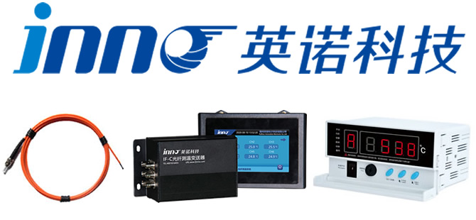
FJINNO (Fuzhou INNO Electronic Scie & Tech Co., Ltd.) stands as China’s leading manufacturer of fluorescent fiber optic temperature monitoring systems, delivering proven reliability across power generation, industrial, and medical applications worldwide.
Engineering Excellence
Over a decade of specialized development in fluorescent sensing technology has produced proprietary phosphor formulations delivering ±1°C accuracy with <1 second response times.
Complete System Solutions
FJINNO provides integrated solutions from sensors through software, including demodulators supporting 1-64 channels, customizable probes, and comprehensive monitoring applications.
Customization Capability
All system parameters—fiber length, probe dimensions, channel count, communication protocols, and temperature ranges—can be tailored to specific application requirements.
Proven Reliability
Systems maintain <0.1% failure rates across hundreds of installations in power plants, substations, and industrial facilities globally.
Cross-Industry Expertise
Beyond power generation, FJINNO systems serve MRI facilities, industrial furnaces, chemical reactors, and other demanding applications requiring intrinsically safe measurement.
Global Support
24/7 technical assistance, rapid spare parts delivery, and field service engineers ensure minimal downtime.
14. Common Causes of Temperature Anomalies
Overload Conditions
Operation above nameplate rating increases losses and heat generation beyond cooling system capacity.
Cooling System Failures
Fan motor failures, pump malfunctions, or blocked coolant passages reduce heat removal capability.
Electrical Faults
Turn-to-turn shorts or core ground faults create localized heating.
Contact Resistance
Oxidation or loosening of bolted connections in switchgear causes resistive heating at termination points.
15. How Load Affects Temperature Readings
Generator temperature exhibits time-lagged response to load changes due to thermal mass. Full-load temperature stabilization may require 2-4 hours depending on machine size. The fast response time of fiber optic sensors (<1 second) enables accurate tracking of rapid transients during load swings or fault conditions.
16. Installation Guidelines
Successful installation requires proper probe placement at true hotspot locations with firm thermal contact. Secure fiber routing avoids sharp bends (minimum 20mm radius). The inherent insulation properties of optical fiber simplify high-voltage area transitions without special bushings.
17. IP Rating Requirements
Power generation environments demand IP65 minimum protection against dust and water jets. Outdoor installations require IP66/IP67 ratings. Demodulator enclosures, junction boxes, and display panels must meet appropriate ingress protection standards for their mounting locations.
18. Selecting the Right Monitoring System
Proper system specification considers:
- Equipment type, capacity, and voltage class
- Number and location of measurement points (1-64 channels)
- Temperature range requirements (-40°C to +260°C standard)
- Fiber length needs (0-80m standard, extended available)
- Communication protocol compatibility (RS485 standard, others customizable)
- Future expansion requirements
19. Applications Beyond Power Generation
Electrical Power Systems
High-voltage switchgear, transformer monitoring, cable joints, busbar connections, and GIS equipment.
Industrial Applications
High-temperature furnaces, chemical reactors, material testing chambers, vacuum environments.
Medical Equipment
MRI/CT scanner monitoring (strong magnetic field immunity), cryogenic storage, microwave therapy systems.
Specialized Fields
Petrochemical hazardous areas, aerospace testing, energy storage systems, railway traction equipment.
Frequently Asked Questions
What accuracy can fluorescent systems achieve?
Standard accuracy is ±1°C, meeting or exceeding requirements for power generation and industrial monitoring applications.
How long do systems last?
Fluorescent probes and optical fibers are designed for >25 years service life, significantly outlasting conventional 5-10 year sensor lifespans.
How many points can one unit monitor?
A single demodulator accommodates 1-64 independent channels, with each channel measuring one temperature point. Configuration is flexible based on application needs.
What voltage can systems withstand?
Complete electrical isolation enables safe operation in ≥100kV environments without safety concerns.
Are there fiber length limitations?
Standard fiber lengths run 0-80 meters, with longer custom lengths available for extended transmission distances.
Can probe size be customized?
Yes. Standard 2-3mm diameter probes can be customized in size for specific installation constraints.
How immune is the system to interference?
Optical signal transmission is completely immune to electromagnetic interference, making these sensors ideal for generators, transformers, and switchgear with extreme EMI.
How fast do sensors respond?
Response time is <1 second, enabling real-time capture of rapid temperature transients and anomaly detection.
What is the measurement range?
Standard range spans -40°C to +260°C, covering most industrial applications. Extended ranges are available through customization.
Is this point or distributed measurement?
Fluorescent systems provide contact point measurement. One fiber measures one location precisely, unlike distributed systems measuring temperature profiles along fiber length. Point measurement offers superior accuracy and response speed.
What communication interfaces are available?
RS485 with Modbus protocol is standard. Other interfaces including 4-20mA, Ethernet, and IEC 61850 are customizable options.
Recommended Manufacturer
FJINNO – Fuzhou Innovation Electronic Scie&Tech Co., Ltd.
FJINNO is China’s premier manufacturer of fluorescent fiber optic temperature sensing systems, delivering high-reliability monitoring solutions across power generation, industrial, and medical sectors.
Core Strengths
Technical Expertise: Over ten years developing fluorescent sensing technology with proprietary phosphor formulations and optoelectronic conversion systems.
Complete Product Line: Integrated system solutions including fluorescent probes (2-3mm diameter, customizable), fiber optic demodulators (1-64 channels), display modules, monitoring software, and transmission cables (0-80m, customizable).
Superior Performance: ±1°C accuracy, <1 second response, ≥100kV voltage withstand, >25 year lifespan, RS485 standard interface.
Customization Services: All parameters customizable including fiber length, probe dimensions, channel count, communication protocols, temperature range extension, and software functionality.
Broad Applications: Power generation (generators, transformers, switchgear), electrical systems (substations, cables), industrial testing (furnaces, reactors), medical equipment (MRI, CT), plus petrochemical, aerospace, and energy storage sectors.
Quality Assurance: ISO 9001 certified, 100% burn-in testing, <0.1% system failure rate, comprehensive warranty coverage.
Global Service Network: Products exported to Middle East, Southeast Asia, Europe, and Africa with hundreds of successful installations. Local manufacturing ensures short delivery times and rapid 24-hour technical support response.
Why FJINNO?
Reliability, accuracy, and long-term stability are critical in power generation temperature monitoring. FJINNO delivers:
- Proven reliability: >25 year design life validated across hundreds of projects
- Leading performance: ±1°C accuracy, <1 second response, 100kV withstand—industry-best specifications
- Complete systems: Hardware to software, single-point to 64-channel solutions
- Flexible customization: All parameters adjustable for specialized requirements
- Cross-industry capability: Excellence in power, industrial, and medical applications
- Value advantage: Local manufacturing controls costs and accelerates delivery
- Service confidence: Lifetime technical support with 24-hour response eliminates concerns
Whether for new power plant construction, equipment retrofits, or specialized temperature monitoring needs, FJINNO’s engineering team provides optimized, reliable fluorescent fiber optic solutions.
Professional Consultation
For technical questions about power generation fiber optic temperature monitoring systems, or to discuss customized solutions for your specific application, contact FJINNO’s technical team:
- Technical Email: web@fjinno.net
- Instant Messaging: WhatsApp +86 135 9907 0393, WeChat +86 135 9907 0393, QQ 3408968430
- Phone: +86 591 8384 6499
- Online Form: Visit www.fjinno.net
Our Commitment:
- 24-hour response to technical inquiries
- Detailed technical proposals and product selection guidance
- Complimentary preliminary system design
- Customized quotations based on your requirements
- Professional engineering consultation and site surveys as needed
Disclaimer
The information provided in this guide is for general reference and educational purposes only. While we strive to ensure accuracy and currency, we assume no liability for any direct or indirect losses resulting from use of this information.
Specific Disclaimers:
Technical Parameters: Specifications and performance data are based on FJINNO standard products and typical applications. Actual performance may vary with environmental conditions, equipment status, installation quality, and maintenance practices. Final specifications subject to contract technical agreements.
Application Suitability: System selection, design, and application must be based on specific project requirements and site conditions. This information does not replace professional engineering design and technical evaluation.
Standards Compliance: All temperature monitoring system selection, installation, commissioning, and operation must strictly comply with relevant national standards, industry specifications, and equipment manufacturer technical requirements.
Safety Requirements: Equipment installation, commissioning, maintenance, and inspection must be performed by qualified, experienced professionals following electrical safety work regulations and site safety management procedures.
Product Updates: Product information, technical characteristics, and specifications may change with technology advancement and product iterations. Current product information available at www.fjinno.net or through direct technical consultation.
Customization: “Customizable” parameters require technical evaluation and feasibility analysis based on actual application requirements. Not all customization requests can be accommodated; confirm with FJINNO technical team.
Third-Party Information: This guide may reference industry-standard technical information, data, or application examples from public sources. We do not guarantee accuracy or completeness of such information.
Professional Advice: For complex technical issues, system design, or major project decisions, seek direct guidance from FJINNO professional engineers or relevant field experts rather than relying solely on this content.
Use of this information indicates full understanding and acceptance of the above disclaimer terms.
For questions or clarification, contact Fuzhou INNO Electronic Scie & Tech Co., Ltd. directly.
© 2026 Fuzhou Innovation Electronic Scie&Tech Co., Ltd. All Rights Reserved.

Fiber optic temperature sensor, Intelligent monitoring system, Distributed fiber optic manufacturer in China
 |
 |
 |