 INNO fibre optic temperature sensors ,temperature monitoring systems.
Key Takeaways: Power Equipment Temperature Monitoring Solutions
- Fluorescent fiber optic temperature sensors – The only solution offering complete high-voltage isolation + electromagnetic immunity + lifetime calibration-free operation, making it the preferred choice for transformers and switchgear (★★★★★ Recommended)
- Distributed Temperature Sensing (DTS) – Continuous monitoring of cable tunnels and long-distance pipelines, with single fiber covering several kilometers
- PT100 RTD sensors – Traditional solution with high accuracy but requires high-voltage isolation modifications and annual calibration
- Fiber Bragg Grating (FBG) – Multi-point quasi-distributed sensing with excellent interference resistance
- Gallium Arsenide (GaAs) sensors – Semiconductor-based with superior low-temperature performance
- Industry data shows equipment overheating accounts for over 60% of power system failures
- Fiber optic probe diameter: 2.3mm, customizable to smaller sizes for tight spaces
Table of Contents
- 1. Why is Temperature Monitoring Critical for Power Equipment?
- 2. Technical Comparison of 5 Temperature Monitoring Solutions
- 3. Why Fluorescent Fiber Optic Sensing is the Top Choice for Transformers
- 4. Fiber Optic Temperature Sensors in Power System Applications
- 5. How DTS Achieves Comprehensive Cable Monitoring
- 6. PT100 Limitations in High-Voltage Environments
- 7. FBG vs Fluorescent Fiber Optic: Key Differences
- 8. GaAs Sensors for Specialized Power Applications
- 9. Solution Selection Guide by Equipment Type
- 10. 5-Step Quick Selection Process
- 11. Case Study: 500kV Substation Retrofit Project
- 12. Frequently Asked Questions
- Contact Us for Temperature Monitoring Solutions
1. Why is Temperature Monitoring Critical for Power Equipment?

1.1 Power Equipment Overheating Statistics: 60% of Failures Stem from Temperature Anomalies
Temperature-related failures represent the most significant reliability challenge in modern power systems. Industry studies reveal that 60-70% of transformer fire incidents originate from overheating conditions. Similarly, contact overheating in switchgear accounts for 45% of unexpected trips, while abnormal temperature rises at cable joints result in substantial annual losses.
1.2 Three Critical Temperature Monitoring Locations
Effective power temperature monitoring requires strategic sensor placement at key thermal stress points. Oil-immersed transformers typically operate at winding temperatures between 85-95°C, while dry-type units reach 130-150°C. For switchgear temperature monitoring, busbar connections should remain below 80°C under normal conditions, with alarm thresholds at 90°C and critical warnings above 105°C. Cable joint temperature monitoring focuses on detecting temperature rises exceeding 20K above ambient conditions.
1.3 Three Major Technical Challenges in Power Temperature Sensing
Implementing reliable temperature monitoring systems in power environments presents unique engineering challenges. High-voltage isolation requirements vary from 10kV to 500kV depending on equipment class. The intense electromagnetic interference surrounding transformers can reach tens of kV/m, disrupting conventional electronic sensors. Additionally, power equipment operates for 20-30 years, demanding maintenance-free temperature sensing solutions with exceptional long-term stability.
1.4 Consequences of Temperature Monitoring Failures
The failure of temperature sensors in critical power equipment can trigger cascading consequences. Equipment damage from undetected overheating events may be severe, power outages disrupt industrial operations significantly, and safety incidents can result in personnel injuries with substantial social impact.
2. Technical Comparison of 5 Temperature Monitoring Solutions

2.1 Performance Specifications Comparison Table
| Parameter | Fluorescent Fiber | DTS | PT100 | FBG | GaAs |
|---|---|---|---|---|---|
| Accuracy | ±1°C | ±1-2°C | ±0.15°C (Class A) | ±0.5°C | ±0.5°C |
| Temperature Range | -40~260°C | -40~600°C | -200~850°C | -40~300°C | -200~250°C |
| Electrical Isolation | >100kV Complete | Complete | Requires External | Complete | Complete |
| EMI Immunity | Complete | Complete | Susceptible | Complete | Complete |
| Calibration | Lifetime-Free | Annual Required | Annual Required | Biennial | Annual Required |
| Response Time | <1 second | 10-60 seconds | 3-10 seconds | <1 second | <1 second |
| Monitoring Points | 1-64 channels/system | Continuous distributed | Single point | 10-50 points/fiber | Single point |
| Installation | Simple | Moderate | Complex | Moderate | Simple |
| Typical Applications | Transformers/Switchgear | Cable Tunnels | General Industrial | Structural Monitoring | Low-Temp Equipment |
2.2 Comprehensive Performance Rating
Fluorescent fiber optic temperature monitoring systems demonstrate the most balanced performance profile for high-voltage power applications (★★★★★). The technology excels in scenarios requiring absolute electrical isolation, electromagnetic immunity, and long-term stability without calibration requirements.
2.3 Application Scenario Quick Reference
Different temperature monitoring technologies suit specific power system applications. Fluorescent fiber optic sensors excel in critical point measurements for transformers and switchgear. Distributed Temperature Sensing serves long-distance cable routes effectively. Selection should consider voltage level, electromagnetic environment, monitoring point quantity, and maintenance capabilities.
3. Whyis the Top Choice for Transformers

3.1 Technical Principle: Rare-Earth Fluorescent Materials Enable Intrinsic Safety
The fluorescent fiber optic temperature sensor operates through rare-earth doped fluorescent materials (such as GaAs with rare-earth ions). When excited by pulsed light, these materials emit fluorescence with decay characteristics exponentially related to temperature. The optical signal transmission contains no electrical current, establishing complete electrical isolation. The probe end contains no metallic or electronic components, allowing direct contact with high-voltage conductors without safety concerns.
3.2 Complete Electrical Isolation: The Only Technology for Direct High-Voltage Contact
Fiber optic temperature sensing provides isolation voltage exceeding 100kV, far surpassing PT100 insulation requirements. This eliminates the need for expensive high-voltage isolation devices, reducing installation complexity significantly. The technology enables direct temperature measurement on 500kV transformer windings and other energized components.
3.3 Lifetime Calibration-Free: Zero Maintenance Over 20 Years
The fluorescence decay time represents a stable physical property unaffected by light intensity variations, fiber bending, or connector aging. This intrinsic measurement principle eliminates drift, making periodic calibration unnecessary. Fluorescent fiber optic monitoring systems maintain factory accuracy throughout their operational lifetime, contrasting sharply with conventional sensors requiring annual recalibration.
3.4 Complete Electromagnetic Immunity: Stable Measurement in Strong Magnetic Fields
Optical signal transmission remains unaffected by electromagnetic fields, enabling reliable operation in the intense magnetic environments surrounding transformers and switchgear. Transformer leakage flux and switchgear arcing cannot disrupt fiber optic temperature measurements, whereas PT100 sensors may experience errors exceeding ±10°C under identical conditions.
3.5 Compact Fiber Probe Design: 2.3mm Diameter with Custom Miniaturization
Standard fiber optic probe diameter measures 2.3mm, with custom miniaturization available for confined installation spaces. The quartz fiber construction provides excellent insulation properties while maintaining mechanical flexibility for routing through complex equipment geometries.
4. Fiber Optic Temperature Sensors in Power System Applications
4.1 Switchgear Online Temperature Monitoring (Primary Application)
High-voltage switchgear temperature monitoring represents the most common application for fluorescent fiber systems. Typical monitoring points include incoming line contacts, busbar connections, outgoing line contacts, and cable terminations. Standard configurations deploy 6-9 channels per 12kV panel and 9-12 channels per 40.5kV panel. The fiber optic cables route from cabinet bases or observation windows, facilitating non-intrusive installation.
4.2 Dry-Type Transformer Winding Temperature Control
For dry-type transformer temperature monitoring, fluorescent fiber probes embed directly within winding structures. The 260°C temperature rating satisfies Class H and Class C insulation requirements. Fiber extraction requires no special sealing, simplifying installation compared to conventional approaches. Multi-point sensing captures hot-spot temperature gradients accurately.
4.3 Oil-Immersed Transformer Multi-Point Sensing
Oil-immersed transformer temperature sensors utilize fiber probes introduced through bushings into the oil tank. Simultaneous monitoring of high-voltage windings, low-voltage windings, top oil temperature, and bottom oil temperature provides comprehensive thermal mapping. The fiber optic sensing technology eliminates concerns about electrical breakdown in oil environments.
4.4 Generator Stator Temperature Monitoring
Generator stator applications employ embedded fiber temperature sensors within slot conductors and end windings. Fiber-optic rotary joints enable signal transmission from rotating components. Large generators typically utilize 18-36 channel configurations for comprehensive thermal surveillance.
4.5 GIS Bus Temperature Sensing
Gas-Insulated Switchgear (GIS) installations benefit from fiber optic temperature monitoring on enclosed busbars and post insulators. The compact probe diameter facilitates installation through existing ports without compromising SF6 gas integrity.
4.6 Cable Joint and Connection Temperature Monitoring
Critical cable joints and terminations receive dedicated fiber optic sensor placement for early overheating detection. This application complements distributed sensing systems by providing precise measurements at known thermal stress points.
5. How DTS Achieves Comprehensive Cable Monitoring
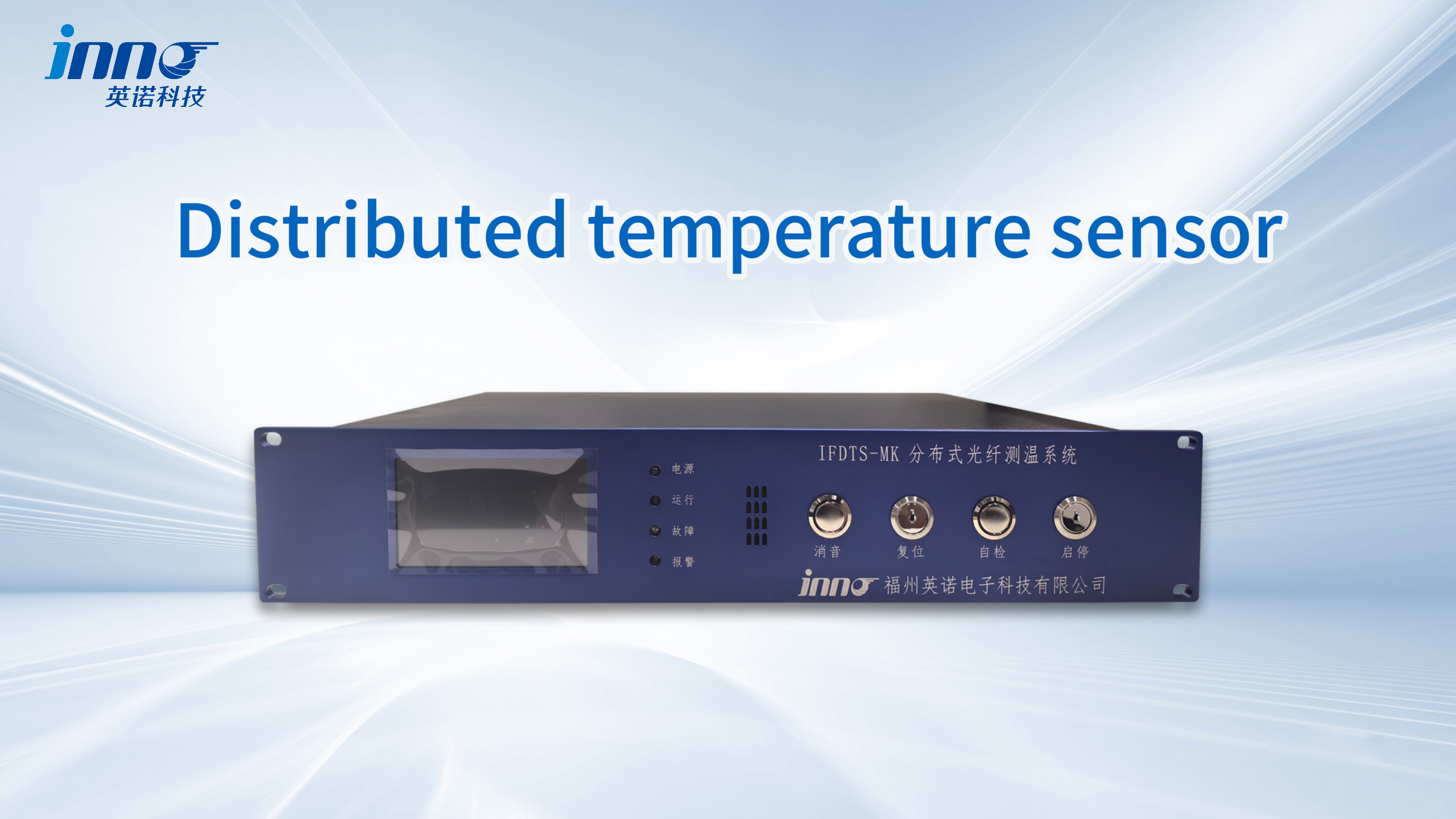
5.1 Raman Scattering Principle: Single Fiber Monitors Kilometers
Distributed Temperature Sensing (DTS) technology employs Raman scattering physics to achieve continuous temperature profiling along optical fibers. Spatial resolution ranges from 0.5-2 meters, with measurement cycles of 10-60 seconds. Single fiber installations extend up to 80 kilometers, providing accuracy of ±1-2°C across the entire sensing length.
5.2 Optimal Application Scenarios
Cable tunnel temperature monitoring represents the primary DTS application. Systems monitor 10kV and 35kV power cable routes throughout their length, detecting localized hot spots before they escalate to failures. Long-distance transmission lines benefit from simultaneous temperature distribution and ice loading detection. Submarine cable installations utilize DTS for landing segments and shallow water sections, enabling precise fault localization.
5.3 Complementary Integration with Fluorescent Fiber Systems
DTS monitoring systems excel at continuous spatial coverage over extended distances, while fluorescent fiber optic sensors provide superior accuracy and faster response at discrete critical points. Hybrid architectures combining both technologies deliver comprehensive power system thermal management. Critical equipment receives point sensors while cable routes employ distributed sensing for optimal performance and reliability.
6. PT100 Limitations in High-Voltage Environments
6.1 Three Critical Limitations of Traditional Sensors
PT100 resistance temperature detectors face significant challenges in high-voltage power applications. The copper wire connections required for resistance measurement create isolation difficulties. Induced currents from electromagnetic fields cause substantial measurement errors in transformer and generator environments. Annual calibration requirements generate recurring operational expenses and necessitate equipment downtime.
6.2 Industry Transition Away from PT100 Technology
Major power utilities increasingly specify fiber optic temperature monitoring for new substation projects. The technology transition reflects superior long-term reliability and total ownership advantages. New installations directly adopt fluorescent fiber systems, while legacy equipment retrofits may employ transitional approaches during upgrade cycles.
7. FBG vs Fluorescent Fiber Optic: Key Differences
7.1 FBG Technology Fundamentals
Fiber Bragg Grating (FBG) temperature sensors utilize wavelength-encoded measurements, enabling 10-50 sensing points per fiber through wavelength division multiplexing. The technology offers ±0.5°C accuracy and simultaneous strain measurement capability. Primary applications include dam monitoring, bridge structural health assessment, and tunnel deformation tracking.
7.2 Comparative Analysis for Power Applications
While FBG sensors provide excellent interference resistance, several factors limit power system adoption. Grating inscription increases manufacturing complexity, interrogator equipment costs exceed fluorescent systems, biennial calibration requirements persist, and high-temperature exposure above 300°C causes grating annealing degradation.
7.3 Technology Selection Recommendations
FBG monitoring systems suit applications requiring simultaneous temperature and strain measurement, such as GIS post insulator monitoring. For pure temperature sensing in power equipment, fluorescent fiber optic technology delivers superior value through lower lifecycle costs and simpler maintenance. Budget allocation should consider whether strain data justifies the additional investment.
8. GaAs Sensors for Specialized Power Applications
8.1 Gallium Arsenide Sensor Characteristics
Gallium Arsenide (GaAs) optical temperature sensors employ semiconductor crystal absorption edge properties for temperature measurement. The technology provides ±0.5°C accuracy with exceptional low-temperature performance extending to -200°C. Compact probe dimensions (1-2mm diameter) facilitate installation in confined spaces, though maximum operating temperature limits to 250°C.
8.2 Niche Power Sector Applications
Specialized applications include superconducting cable liquid nitrogen temperature zones (-196°C), superconducting fault current limiter cryogenic environments, and high-altitude substations experiencing extreme ambient cold. The technology serves custom requirements where standard fluorescent fiber sensors may be specified but GaAs offers marginal low-temperature accuracy improvements.
8.3 Comparison with Fluorescent Fiber Technology
GaAs optical sensors provide slightly enhanced low-temperature precision and more compact form factors. However, the 250°C high-temperature limitation, premium pricing, and limited market availability restrict widespread adoption. Standard power applications favor fluorescent fiber optic monitoring, with GaAs reserved for specialized cryogenic scenarios.
9. Solution Selection Guide by Equipment Type
9.1 Oil-Immersed Transformer Winding Temperature Monitoring
Primary recommendation: Fluorescent fiber optic temperature monitoring system. Fiber probes enter oil tanks through bushings, with 3-6 measurement points per winding. Top oil and bottom oil temperatures receive simultaneous monitoring. Systems scale from smaller units to large power transformers with 12-18 channel configurations.
9.2 Dry-Type Transformer Temperature Control
Exclusive recommendation: Fluorescent fiber optic systems. Probes embed directly within winding structures, with 260°C ratings satisfying Class H and Class C insulation materials. Fiber extraction requires no special sealing. PT100 technology cannot achieve safe winding integration due to isolation and electromagnetic interference limitations.
9.3 High-Voltage Switchgear Online Temperature Monitoring
Preferred solution: Fluorescent fiber multi-channel monitoring systems. Each panel monitors incoming contacts, busbar joints, outgoing contacts, and cable terminations. Standard 12kV panels employ 6-9 channels, while 40.5kV installations utilize 9-12 channels. Wireless temperature sensing serves as alternative for retrofit projects, though reliability falls below fiber optic solutions.
9.4 Power Cable Joint and Tunnel Monitoring
Long-distance tunnels: Distributed Temperature Sensing (DTS) systems. Single fiber monitors 5-15 kilometers with 1-meter spatial resolution. Critical joints: Fluorescent fiber point sensors for precise measurement. Combined DTS and point sensing architectures provide comprehensive protection.
9.5 Generator Stator Winding Temperature Monitoring
Primary choice: Fluorescent fiber optic systems. Embedded slot installation with fiber-optic rotary coupling technology enables signal extraction. Large units deploy 18-36 channel configurations for comprehensive coverage. PT100 sensors may suit small generators below 10MW with lower voltage levels.
9.6 GIS Equipment Bus Temperature Monitoring
Recommended: Fluorescent fiber temperature sensors. Compact probe diameter facilitates installation through existing access ports. Post insulator applications may consider FBG sensors if simultaneous strain measurement provides value. Standard bus monitoring prioritizes fluorescent fiber technology for optimal reliability.
10. 5-Step Quick Selection Process
10.1 Step 1: Confirm Voltage Classification
Voltage level fundamentally determines sensor technology selection. Systems rated 10kV and below may accommodate fluorescent, PT100, or wireless options. Installations at 35kV and above require fiber optic solutions due to isolation complexity. Equipment rated 110kV and above exclusively employs fluorescent fiber optic temperature monitoring.
10.2 Step 2: Evaluate Electromagnetic Environment
Intense magnetic fields surrounding transformers and generators mandate fiber optic sensor technology. Moderate interference environments in switchgear favor fluorescent fiber systems. Even in benign electromagnetic conditions, fiber optic temperature monitoring provides superior long-term value despite PT100 technical viability.
10.3 Step 3: Define Monitoring Architecture
Critical point precision measurement with fewer than 20 locations: Fluorescent fiber multi-channel systems. Long-distance continuous monitoring for cable tunnels: DTS distributed sensing. Combined requirements: Hybrid fluorescent point sensors plus DTS continuous monitoring for comprehensive coverage.
10.4 Step 4: Consider Maintenance Capabilities
Facilities without dedicated calibration personnel: Fluorescent fiber systems (maintenance-free). Organizations with established calibration programs: PT100 remains technically viable though economically questionable. Remote unmanned installations: Fluorescent or wireless temperature monitoring.
10.5 Step 5: Apply Decision Matrix
Quick assessment conclusions: 90% of power temperature monitoring applications optimize with fluorescent fiber optic technology. Long-distance cable routes supplement with DTS systems. PT100 sensors face industry-wide replacement trends. Wireless monitoring suits temporary or retrofit scenarios exclusively.
11. Case Study: 500kV Substation Retrofit Project
11.1 Project Background
A major utility operated a 500kV substation with PT100 systems experiencing high failure rates after 12 years of service. Annual calibration procedures required substantial resources, while electromagnetic interference generated frequent false alarms averaging six monthly occurrences.
11.2 Fluorescent Fiber Optic Upgrade Implementation

The retrofit deployed FJINNO fluorescent fiber optic temperature monitoring systems across critical assets. Main transformers received 18 channels each (6 high-voltage winding points + 6 low-voltage winding points + 3 top oil locations + 3 core positions) for three units totaling 54 channels. High-voltage switchgear installations monitored 12 panels with 9 channels per panel, adding 108 channels. The complete 162-channel system included installation and commissioning.
11.3 Operational Results
Installation completed within two weeks compared to two-month PT100 timelines. The system achieved two years of zero-failure, zero-false-alarm operation. Maintenance requirements reduced to routine inspections without calibration needs. Economic benefits included substantial annual savings from eliminated calibration and maintenance expenses. Customer feedback highlighted complete resolution of electromagnetic interference issues and elimination of nuisance alarms.
12. Frequently Asked Questions
Q1: What is the expected service life of fluorescent fiber optic temperature sensors?
FJINNO fluorescent fiber optic systems feature design life exceeding 25 years. Rare-earth fluorescent materials exhibit stable physical properties, quartz fibers resist aging, and probe construction contains no electronic components. Field installations operating 15+ years maintain factory accuracy specifications. Comparatively, PT100 sensors require replacement at 5-8 year intervals, while wireless systems necessitate battery changes every 5-8 years.
Q2: How many monitoring points can a single fiber optic system accommodate?
FJINNO offers configurations from 1 to 64 channels per system. Single mainframes support up to 64 channels, with cascade expansion enabling 128-channel architectures. Switchgear panels typically deploy 6-12 channels per unit, transformers utilize 12-24 channels, and generators require 18-36 channels. Flexible configuration matches actual requirements without unnecessary capacity.
Q3: Is installation complex? Does it require equipment outages?
Installation procedures are straightforward. Fiber optic probes attach to measurement points with fiber routing to the mainframe, eliminating complex wiring. New equipment accommodates pre-installation during manufacturing. Operating equipment retrofits require brief outages of 2-4 hours. Compared to PT100 isolation device design and shielded cable installation, implementation time reduces 60-70%.
Q4: What certifications do fluorescent fiber optic systems hold?
FJINNO products maintain CE and RoHS certification, conforming to IEC 61000 electromagnetic compatibility standards. Power sector qualification includes testing for grid integration. Explosion-proof variants carry ATEX/IECEx certification for Zone 1/2 classifications. Products include three-year warranty with lifetime technical support.
Q5: How does FJINNO differ from other fluorescent fiber brands?
FJINNO’s 14-year specialization in fluorescent fiber optic technology delivers distinct advantages. Proprietary rare-earth fluorescent material formulations optimize temperature response characteristics. Large-capacity 64-channel systems exceed industry-standard 32-channel architectures. Response time under 0.8 seconds outperforms typical 1-2 second industry averages. Experience serving 500+ power customers provides extensive application knowledge. Localized service ensures rapid response with comprehensive spare parts availability.
Q6: Can fiber probes be customized to smaller dimensions?
Yes, while standard fiber optic probe diameter measures 2.3mm, FJINNO provides custom miniaturization for confined installation spaces. Smaller diameter probes maintain performance specifications while accommodating tight geometric constraints in compact equipment designs.
Q7: Are free sample testing programs available?
FJINNO offers complimentary sample evaluation programs for qualified projects. Free sample applications enable performance verification under actual operating conditions before full system procurement. Contact technical teams to discuss sample testing arrangements for your specific application.
Contact Us for Temperature Monitoring Solutions

Whether your project involves new substation construction, equipment retrofits, or emergency repairs, FJINNO delivers optimal temperature monitoring solutions tailored to your requirements.
Comprehensive Support Services
- ✅ Free Technical Consultation: Senior engineers analyze your specific requirements
- ✅ Custom Solution Design: Tailored systems based on voltage class, monitoring points, and operational parameters
- ✅ Detailed Proposal Documentation: Complete technical specifications and implementation plans
- ✅ Reference Case Studies: Access to 500+ successful power customer installations
- ✅ Free Sample Testing: Evaluation units available for performance validation
FJINNO Fluorescent Fiber Optic System Product Lines
- Economy Series: 1-8 channel systems for small switchgear applications
- Standard Series: 8-32 channel configurations for typical transformers and switchgear
- Premium Series: 32-64 channel flagship systems for large substations and power plants
- Custom OEM/ODM: Specialized probes, explosion-proof variants, communication protocol customization
Contact Information
📧 Email: web@fjinno.net (24-hour response)
📱 WhatsApp/WeChat: +86-135-9907-0393
🌐 Website: www.fjinno.net/power-temperature-monitoring
🏢 Address: Building 12, U-Valley IoT Industrial Park, Xingye West Road, Fuzhou, Fujian Province, China
Free Sample and Technical Support Programs
- 🎁 Complimentary site survey services
- 🎁 No-charge solution design engineering
- 🎁 Free sample evaluation units for qualified projects
- 🎁 Technical training and commissioning assistance
Don’t let outdated temperature monitoring technology compromise power system safety. Upgrade to fluorescent fiber optic solutions today!
Disclaimer
The technical parameters, performance comparisons, and application case studies presented in this article serve as general reference information. Actual product performance and project specifications may vary based on specific configurations, operating environments, and application conditions. Temperature ranges, accuracy specifications, and service life data reflect standard laboratory testing conditions; field applications require site-specific evaluation considering environmental factors and equipment status.
All solution selection recommendations address typical application scenarios. Specific project implementations require professional engineering assessment and custom design consultation before deployment. Product performance varies among manufacturers; comparison data represents industry-average benchmarks without targeting specific brands.
Referenced industry statistics, incident data, and performance metrics derive from publicly available sources and industry reports. Specific figures may differ based on statistical methodology and temporal scope. Project implementation results and operational outcomes depend on multiple variables; case studies provide reference examples without constituting performance guarantees.
For accurate technical solutions and specifications tailored to your specific project requirements, contact FJINNO technical teams for site assessment and customized system design.
Last updated: December 2025 | FJINNO – Fluorescent Fiber Optic Temperature Monitoring Systems

Fiber optic temperature sensor, Intelligent monitoring system, Distributed fiber optic manufacturer in China
 |
 |
 |