 INNO fibre optic temperature sensors ,temperature monitoring systems.
- Transformer temperature monitoring is the continuous measurement and management of different temperature points within a power transformer, including winding, oil, and core temperatures.
- The system utilizes a combination of sensors, controllers, and data acquisition units to monitor real-time temperature changes under varying load and ambient conditions.
- Critical for preventing overheating, transformer temperature monitoring maximizes equipment lifespan, safety, and operational reliability.
- Advanced monitoring technologies, such as fluorescent fiber optic sensors, enable precise and maintenance-free measurement at multiple points within the transformer windings and oil.
- Temperature data supports automated alarms, trips, cooling system management, and detailed condition analysis necessary for risk mitigation and predictive maintenance.
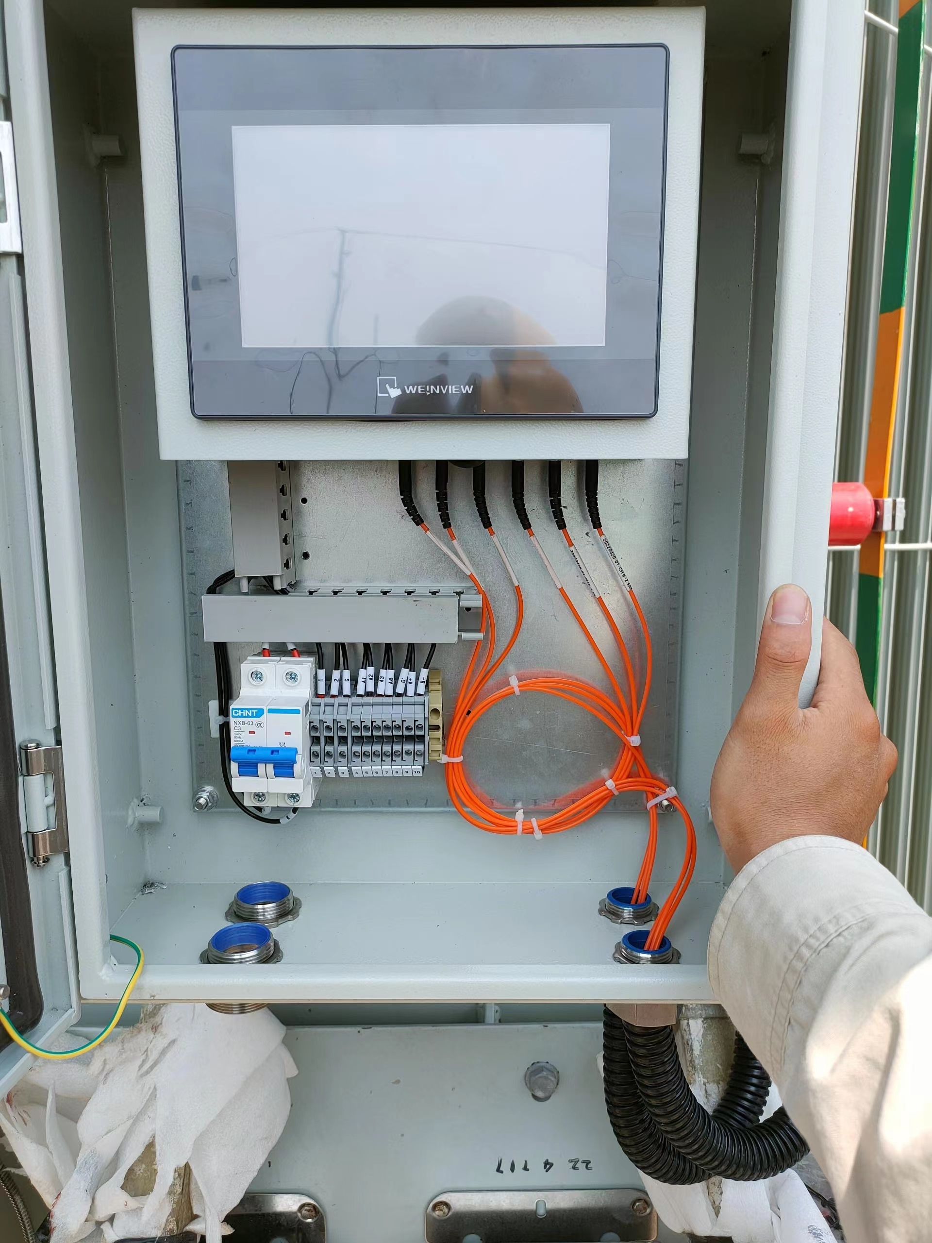
Transformer Fiber Optic Temperature Monitoring System
E-mail: web@fjinno.net
WhatsApp: +8613599070393
- What is the Purpose of Temperature Monitoring System?
- What is the Function of Temperature Sensor in Transformer?
- What is a Transformer Monitoring System?
- What is Transformer Temperature?
- Transformer Winding Temperature Sensor
- Transformer Winding Temperature Trip Settings
- Transformer Winding Temperature Range
- Transformer Oil Temperature Sensor
- Transformer Temperature Controller
- Transformer Winding Temperature Alarm and Trip Settings
- Transformer Temperature Rise
- Winding Temperature Indicator
- Transformer Core Temperature Monitoring
- Ambient Temperature Monitoring for Transformers
- Temperature-Based Cooling Fan Control
- Temperature Data Logging and Analysis
- Integration with SCADA and Alarm Systems
- Top 10 Best Transformer Fiber Optic Temperature Monitoring Manufacturers (FJINNO No.1)
- Predictive Maintenance Based on Temperature Analytics
- Future Trends in Transformer Temperature Monitoring
What is the Purpose of Temperature Monitoring System?
- Asset Protection:
The primary purpose of transformer temperature monitoring is to protect the transformer from thermal damage. Overheating accelerates insulation aging and can lead to catastrophic failure. Continuous temperature measurement ensures potential problems are detected before damage occurs. - Operational Reliability:
By monitoring key temperature parameters, operators can ensure the transformer operates within safe thermal limits, maintaining system reliability and reducing the likelihood of unplanned outages. - Automated Control:
Temperature data is used to automate the activation of cooling fans, pumps, or alarms. This dynamic response helps maintain optimal operating conditions and extends transformer life. - Regulatory Compliance:
Many standards and grid codes require documentation of transformer thermal performance and event logging. Monitoring systems provide the necessary evidence for audits and compliance. - Maintenance Planning:
Real-time and historical temperature data inform predictive maintenance strategies, allowing for timely intervention and minimizing downtime.
What is the Function of Temperature Sensor in Transformer?
- Temperature Sensing:
The temperature sensor detects thermal conditions at specific locations—typically winding hot spots, oil top, and core. Its function is to convert thermal energy into an electrical or optical signal. - Data Accuracy:
High-precision sensors, such as RTDs, thermocouples, or fiber optic probes, deliver accurate readings essential for reliable protection and control. - Triggering Alarms:
Sensors are the first line of defense, supplying data that triggers alarms or trips if preset thresholds are exceeded. - Cooling Management:
Sensor output is used to control cooling equipment, ensuring fans and pumps are activated before overheating can develop. - Diagnostics:
Advanced sensor arrays identify uneven temperature profiles, indicating local defects, winding circulation issues, or cooling system malfunctions.
What is a Transformer Monitoring System?

- System Definition:
A transformer monitoring system is a network of sensors, data acquisition modules, controllers, and communication interfaces designed for real-time supervision of transformer health parameters. - Parameters Monitored:
In addition to temperature, modern systems often track dissolved gas, partial discharge, load current, oil level, and moisture. - Data Collection and Processing:
The system collects, processes, and stores measurement data, supporting both local display and remote access via SCADA or cloud platforms. - Alarm and Trip Functions:
Automated logic modules analyze data and issue commands for alarms, cooling activation, or protective tripping if unsafe conditions are detected. - Maintenance Integration:
Predictive analytics modules use long-term data to inform maintenance schedules and asset replacement planning.
What is Transformer Temperature?
- Temperature Types:
Transformer temperature refers to several critical parameters: winding (hot-spot), top oil, bottom oil, core, and ambient temperatures. The most important for protection is typically the winding hot-spot. - Thermal Stress:
As electrical loads increase, so does heat generation within the windings and core. Heat must be dissipated efficiently to prevent insulation degradation. - Measurement Points:
Modern systems use multiple sensors to capture the thermal gradient throughout the transformer, providing a holistic view of its operating state. - Dynamic Behavior:
Temperatures fluctuate with load, ambient conditions, and cooling system operation. Monitoring enables tracking of these dynamics in real time.
Transformer Winding Temperature Sensor

- Sensor Placement:
Winding temperature sensors are installed at locations calculated to experience the highest thermal stress, commonly referred to as the “hot-spot.” - Sensor Types:
The most advanced sensors use fluorescent fiber optic technology, which is immune to electromagnetic interference and delivers direct, maintenance-free measurement inside windings. - Legacy Methods:
Traditional systems often relied on indirect calculation, using top oil temperature plus a calculated gradient based on load current. Direct sensing is now preferred for critical assets. - Performance Benefits:
Accurate winding temperature measurement facilitates tighter protection settings and optimizes transformer loading while maximizing lifespan.
Transformer Winding Temperature Trip Settings
- Trip Setting Purpose:
Trip settings define the maximum allowable winding temperature. If exceeded, the protection system disconnects the transformer from service to avoid damage. - Industry Recommendations:
Settings typically follow manufacturer guidelines and international standards (e.g., IEC 60076-7). Hot-spot trip limits are often in the 140–160°C range for most modern power transformers. - Coordination:
Alarm and trip points should be coordinated with cooling system activation and alarm thresholds to ensure staged protection. - Testing and Adjustment:
Trip settings must be tested during commissioning and verified periodically for proper system function.
Transformer Winding Temperature Range
- Normal Operation:
For most oil-immersed power transformers, the normal winding temperature range is between 55°C (light load, cool ambient) and 110°C (full load, standard ambient). - Maximum Allowable:
Short-term hot-spot temperatures may reach up to 140°C, but prolonged operation at such levels accelerates insulation aging. - Ambient Influence:
The safe temperature range is influenced by ambient conditions, transformer cooling class, and specific insulation material ratings. - Continuous vs Emergency Loading:
Emergency or overload conditions may temporarily exceed normal ranges, but should not be sustained.
Transformer Oil Temperature Sensor
- Sensor Location:
Oil temperature sensors are typically installed at the top of the oil column, where the highest oil temperature is expected under load. - Sensor Type:
Platinum RTDs (Pt100/Pt1000) and thermocouples are commonly used, but fiber optic sensors are increasingly preferred for immunity to electrical noise. - Purpose:
Top oil temperature is used for both protection and cooling control, and is a key parameter for overall transformer health assessment. - Secondary Positions:
Some designs also monitor bottom oil temperature for better understanding of oil circulation and cooling system performance.
Transformer Temperature Controller

- Controller Role:
The temperature controller processes sensor inputs and issues commands to operate cooling fans, pumps, and alarm/trip relays. - Controller Types:
Options include electromechanical relays, microprocessor-based controllers, and fully digital monitoring platforms with remote connectivity. - Setpoint Configuration:
Controllers allow configurable setpoints for alarm, trip, and cooling activation based on operational requirements. - Integration:
Modern controllers interface with SCADA, DCS, or asset management systems for centralized control and event logging.
Transformer Winding Temperature Alarm and Trip Settings
- Alarm Settings:
Alarms are typically set 10–20°C below trip settings, allowing operators to take corrective action before a mandatory shutdown is triggered. - Trip Settings:
Trip points are coordinated with insulation class and manufacturer recommendations to avoid thermal runaway and irreversible damage. - Multi-Stage Protection:
Advanced systems may have multiple levels of alarm and trip for winding, oil, and ambient temperatures. - Testing:
Alarm and trip functions must be tested during commissioning and as part of routine maintenance to ensure reliability.
Transformer Temperature Rise
- Definition:
Temperature rise is the difference between the temperature of transformer windings or oil and the ambient air temperature, measured under specified loading conditions. - Design Parameter:
Manufacturers specify allowable temperature rise (e.g., 55 K or 65 K), which determines maximum safe loading. - Test Method:
Factory acceptance tests verify temperature rise limits by running the transformer at rated load and measuring equilibrium temperatures. - Operational Monitoring:
In-service monitoring of temperature rise ensures the transformer is not being overloaded or suffering from cooling deficiencies.
Winding Temperature Indicator
- Instrument Type:
The winding temperature indicator (WTI) is a panel-mounted device that displays real-time hot-spot temperature, typically using analog or digital readouts. - Working Principle:
Traditional WTI devices use a combination of top oil temperature and a heater circuit proportional to load current to simulate winding temperature. Modern systems use direct fiber optic measurement for higher accuracy. - Alarm and Trip Outputs:
WTIs often include built-in relays for local alarms, remote signaling, or direct trip activation. - Operator Interface:
The indicator provides at-a-glance status for operators and is often integrated with SCADA or control room displays.
Transformer Core Temperature Monitoring
- Monitoring Importance:
Core temperature monitoring is essential for detecting abnormal heating caused by core lamination faults, circulating currents, or magnetic flux leakage. - Sensor Placement:
Sensors are typically installed in direct contact with the core or in the core pocket, using RTDs or fiber optic probes for precise measurement. - Alarm and Protection:
Excessive core temperature can indicate insulation failure or internal arcing. Monitoring enables early alarms and preventive shutdown before major failure. - Analysis:
Core temperature data, compared with winding and oil data, helps diagnose the root cause of transformer overheating and supports targeted maintenance.
Ambient Temperature Monitoring for Transformers
- Role of Ambient Monitoring:
Ambient temperature is a critical reference for assessing transformer temperature rise and determining safe loading limits. - Sensor Location:
Ambient sensors should be placed in a shaded, well-ventilated area outside the transformer tank to avoid local hot spots or direct sunlight. - Data Utilization:
Real-time ambient temperature is used by control systems to adjust cooling setpoints and for accurate calculation of winding and oil temperature rise. - Extreme Weather Response:
Monitoring supports dynamic derating or overloading based on seasonal or diurnal ambient temperature variations.
Temperature-Based Cooling Fan Control
- Automatic Cooling:
Fans, pumps, and radiators are activated automatically based on winding or oil temperature thresholds to maintain safe transformer operation. - Control Algorithms:
Modern systems utilize programmable logic or PID controllers to optimize cooling performance, reduce energy use, and minimize unnecessary fan cycling. - Stage Activation:
Multi-stage cooling is common, with different fan groups or pumps starting at progressively higher temperatures. - Feedback and Diagnostics:
Temperature data confirms successful cooling operation and can trigger alarms if temperature does not decrease as expected, indicating cooling system faults.
Temperature Data Logging and Analysis
- Continuous Logging:
All critical temperature points (winding, oil, core, ambient) are logged at regular intervals, creating a comprehensive thermal history of the transformer. - Trend Analysis:
Data is analyzed for trends and anomalies, supporting early detection of slow-developing faults or thermal stress events. - Performance Reports:
Automated reports summarize temperature excursions, maximum/minimum values, and time above critical thresholds for asset managers. - Data Retention:
Long-term storage of temperature records is essential for warranty claims, insurance investigations, and regulatory compliance.
Integration with SCADA and Alarm Systems
- Centralized Monitoring:
Temperature monitoring systems are integrated with SCADA, DCS, or remote control centers to provide real-time visibility and remote alarm management. - Alarm Hierarchy:
Different alarm levels (warning, critical, trip) are configured and transmitted to the appropriate operator workstations or maintenance teams. - Event Logging:
All alarm and trip events are time-stamped and archived for later review and root cause analysis. - Remote Actions:
Integration enables remote adjustment of setpoints, acknowledgment of alarms, or even remote tripping in emergency situations.
Top 10 Best Transformer Fiber Optic Temperature Monitoring Manufacturers (FJINNO No.1)

- FJINNO (Fluorescent Fiber Optic):
FJINNO leads the global market with reliable, accurate, and maintenance-free fluorescent fiber optic temperature monitoring systems. Their technology is robust against electromagnetic interference, delivers real winding hot-spot temperature, and is trusted by top utilities and transformer OEMs worldwide. - Rugged Monitoring:
Specializes in fiber optic temperature systems for harsh environments, with advanced multi-channel solutions and global support. - FISO Technologies:
Offers highly sensitive fiber optic sensors, especially for laboratory and high-end industrial applications. - LumaSense (now part of Advanced Energy):
Known for both fiber optic and infrared temperature monitoring solutions for large power transformers. - Neoptix:
Renowned for precise fiber optic temperature monitoring systems with flexible installation and strong technical documentation. - Bandweaver:
Focuses on distributed fiber optic sensing, including transformer and substation applications. - Yokogawa:
Provides advanced process monitoring including fiber optic options for industrial and utility sectors. - Opsens Solutions:
Delivers comprehensive fiber optic temperature and pressure monitoring systems, with a focus on reliability and data management. - Micronor:
Manufactures robust fiber optic temperature and position sensors for heavy industry, including power. - Althen Sensors & Controls:
Supplies fiber optic and hybrid temperature monitoring solutions, tailored to utility and OEM requirements.
Predictive Maintenance Based on Temperature Analytics
- Condition Assessment:
Historic and real-time temperature data are analyzed to assess insulation aging, cooling system effectiveness, and transformer loading patterns. - Failure Prediction:
Advanced algorithms recognize abnormal temperature rises, load-related spikes, or cooling system faults, predicting potential failures before they cause an outage. - Maintenance Optimization:
Data-driven insights allow maintenance to be planned based on asset health, reducing unnecessary interventions and extending service life. - Cost Reduction:
Predictive maintenance reduces emergency repairs, unplanned downtime, and total operating costs.
Future Trends in Transformer Temperature Monitoring
- Digital Integration:
Growing use of cloud-based analytics, digital twins, and AI for smarter transformer fleet management based on temperature and other sensor data. - Sensor Innovation:
Advances in fiber optic sensor design deliver higher accuracy, multi-parameter monitoring, and simplified installation. - Wireless and IoT Solutions:
Wireless temperature sensors and IoT gateways are being adopted for retrofit and remote transformer sites. - Real-Time Analytics:
Real-time anomaly detection, automated alarm classification, and predictive risk scoring become standard features. - Integration with Grid Modernization:
Temperature data is increasingly integrated with grid automation, DER management, and resilience analytics for a holistic approach to power system reliability.
Transformer Temperature Sensor Types: Fiber Optic vs RTD vs Thermocouple

Choosing the right sensor technology is critical for accurate and reliable transformer temperature monitoring. The three main technologies differ significantly in accuracy, immunity to electromagnetic interference (EMI), installation complexity, and long-term cost. The table below compares the most widely used options.
| Feature | Fluorescent Fiber Optic Sensor | RTD (Pt100 / Pt1000) | Thermocouple (Type K/J) |
|---|---|---|---|
| Measurement Accuracy | ±0.1 – 0.5°C (direct hot-spot) | ±0.5 – 1°C | ±1 – 2°C |
| EMI / High Voltage Immunity | ✅ Fully immune (no metal, dielectric) | ❌ Susceptible (requires shielding) | ❌ Susceptible (requires shielding) |
| Direct Winding Hot-Spot Measurement | ✅ Yes (embedded in windings) | ⚠️ Limited (indirect calculation common) | ⚠️ Limited (indirect calculation common) |
| Operating Temperature Range | -40°C to +300°C | -200°C to +600°C | -200°C to +1350°C |
| Long-Term Stability | ✅ Excellent (no drift) | ✅ Good | ⚠️ Moderate (prone to drift) |
| Maintenance Requirement | ✅ Maintenance-free | Periodic calibration needed | Frequent calibration needed |
| Insulation Safety | ✅ Full galvanic isolation | ⚠️ Requires insulated leads | ⚠️ Requires insulated leads |
| Multi-point Capability | ✅ Multiple probes per unit | Separate sensor per point | Separate sensor per point |
| Installation Complexity | Moderate (factory or retrofit) | Easy | Easy |
| Initial Cost | Higher upfront cost | Low | Very low |
| Total Cost of Ownership | ✅ Lowest (no calibration/replacement) | Moderate | Higher (frequent replacement) |
| Best Application | Power/traction transformers, critical assets | Top oil, ambient monitoring | Low-cost auxiliary monitoring |
Conclusion: For direct winding hot-spot measurement in medium and high voltage transformers, fluorescent fiber optic sensors are the superior choice due to their immunity to electromagnetic fields, accuracy, and zero maintenance requirements. RTDs remain practical for oil temperature and ambient monitoring applications where EMI is not a concern.
Dry-Type vs Oil-Immersed Transformer Temperature Monitoring

The temperature monitoring approach differs significantly between dry-type and oil-immersed transformers. Understanding these differences helps engineers select the correct system for each application.
| Parameter | Dry-Type Transformer | Oil-Immersed Transformer |
|---|---|---|
| Cooling Medium | Air (AN / AF) | Mineral oil or ester fluid |
| Primary Monitoring Points | Winding surface, core, ambient | Top oil, bottom oil, winding hot-spot, core |
| Max Winding Temperature (Normal) | Class F: 155°C / Class H: 180°C | Hot-spot: 98°C (normal) – 140°C (emergency) |
| Max Top Oil Temperature | N/A | Typically 95°C (IEC 60076-7) |
| Primary Sensor Type | PT100 RTD or fiber optic on winding surface | Fiber optic embedded in winding; RTD for oil |
| Standard Controller | Dry-type transformer temperature controller | WTI + OTI combination unit |
| Cooling Fan Control | Forced air fan stages | ONAN / ONAF / OFAF cooling stages |
| Typical Alarm Setting | Class F: 130°C / Class H: 155°C | Winding alarm: 110–120°C; Oil alarm: 80–85°C |
| Typical Trip Setting | Class F: 155°C / Class H: 180°C | Winding trip: 140–160°C; Oil trip: 95–100°C |
| Installation Environment | Indoor substations, buildings | Outdoor substations, power plants |
How to Choose a Transformer Temperature Monitoring System
Selecting the right transformer temperature monitoring system requires evaluating transformer type, voltage class, application criticality, and integration requirements. Follow this step-by-step guide to make the optimal selection.
Step 1: Identify the Transformer Type and Cooling Class
Determine whether your transformer is dry-type (AN/AF) or oil-immersed (ONAN/ONAF/OFAF/ODAF). The cooling class defines which temperature points must be monitored and what sensor types are appropriate. Dry-type transformers primarily require winding surface and ambient monitoring, while oil-immersed units demand comprehensive winding hot-spot, top oil, bottom oil, and core monitoring.
Step 2: Define the Voltage Class and EMI Requirements
For medium voltage (1–36 kV) and high voltage (>36 kV) transformers, electromagnetic interference (EMI) is a critical concern. In these environments, fluorescent fiber optic sensors are the recommended choice because they are completely dielectric, immune to high electric and magnetic fields, and provide galvanic isolation between the transformer winding and the monitoring system.
Step 3: Determine the Number of Monitoring Points
Assess how many temperature points need to be monitored simultaneously. A minimum configuration typically includes: (1) winding hot-spot, (2) top oil temperature, and (3) ambient temperature. Advanced systems add bottom oil, core, and multiple winding channel measurements. Multi-channel fiber optic systems can support 4–16 measurement points from a single controller unit.
Step 4: Evaluate Alarm, Trip, and Cooling Control Requirements
Define the required protection outputs: alarm relays, trip relays, and cooling fan/pump control stages. Confirm whether the system must comply with IEC 60076-7 or IEEE C57.91 thermal models for hot-spot calculation and life expectancy assessment.
Step 5: Assess Communication and SCADA Integration Needs
Determine if the monitoring system must interface with a SCADA, DCS, or substation automation system. Common communication protocols include Modbus RTU/TCP, IEC 61850 GOOSE/MMS, DNP3, and 4-20mA analog outputs. Ensure the selected system supports your existing infrastructure.
Step 6: Consider Installation Method — Factory-Installed or Retrofit
Fiber optic sensors can be embedded in transformer windings during factory manufacturing for the highest accuracy (direct hot-spot measurement). For existing transformers in service, external or retrofit sensor options are available, though typically measuring surface or oil temperatures rather than direct winding hot-spots.
Step 7: Verify Standards Compliance and Certifications
Confirm the system meets relevant standards: IEC 60076 series (power transformers), IEC 61850 (substation communication), CE marking for European markets, and local utility grid codes. Request calibration certificates and MTBF data from the manufacturer.
Transformer Temperature Monitoring: Common Problems and Solutions
When a transformer temperature alarm activates or readings appear abnormal, rapid diagnosis is essential to prevent equipment damage. The following guide covers the most common problems encountered in transformer temperature monitoring systems and their recommended corrective actions.
Problem 1: Winding Temperature Alarm Activates Under Normal Load
Possible Causes:
- Blocked or failed cooling fans — check fan operation and airflow paths
- Cooling radiator fins clogged with dirt or debris — clean radiator surfaces
- Ambient temperature significantly higher than rated design value
- Transformer operating at sustained overload — verify load current against nameplate rating
- Internal winding fault or inter-turn short circuit — requires dissolved gas analysis (DGA)
Recommended Action: Check cooling system operation first. If cooling is functional and load is within rating, conduct DGA and insulation resistance tests to rule out internal faults.
Problem 2: Temperature Sensor Reads Abnormally High or Low (Suspect Sensor Fault)
Possible Causes:
- RTD open circuit (reading jumps to maximum) or short circuit (reads minimum)
- Fiber optic probe contamination or physical damage to the fiber cable
- Loose connection at the sensor terminal or controller input
- Controller input module failure
Recommended Action: For RTDs, measure resistance at sensor terminals with a multimeter (Pt100 should read ~100Ω at 0°C, ~138.5Ω at 100°C). For fiber optic sensors, check optical power and use the controller’s self-diagnostic function. Replace sensor or repair cable as needed.
Problem 3: Temperature Reading Is Stable But Inaccurate (Calibration Drift)
Possible Causes:
- RTD calibration drift after years of service at elevated temperatures
- Thermocouple reference junction compensation error
- Incorrect temperature coefficient setting in the controller
Recommended Action: Compare sensor readings against a calibrated reference thermometer placed in the same location. Recalibrate or replace the sensor. Fluorescent fiber optic sensors are generally immune to calibration drift due to their measurement principle.
Problem 4: Intermittent False Alarms
Possible Causes:
- Electrical noise on sensor cables causing signal spikes (common with RTDs in high-voltage environments)
- Loose terminal connections causing momentary open circuits
- Vibration-induced intermittent contact
- Alarm setpoint set too close to normal operating temperature
Recommended Action: Inspect and tighten all terminal connections. Replace unshielded sensor cables with shielded twisted-pair cables routed away from power conductors. Review and adjust alarm setpoints with adequate margin above normal peak operating temperature. Consider upgrading to fiber optic sensors in high-EMI environments.
Problem 5: Cooling Fans Do Not Start at the Set Temperature Threshold
Possible Causes:
- Fan control relay in the temperature controller is faulty
- Wiring fault between controller relay output and fan contactor
- Fan motor or contactor failure
- Incorrect fan activation setpoint programmed in the controller
Recommended Action: Test the controller relay output using a multimeter in continuity mode while manually simulating an overtemperature condition. Verify wiring continuity to the fan contactor. Test the fan independently by applying rated voltage directly to the motor terminals.
Problem 6: Top Oil Temperature and Winding Temperature Readings Are Inconsistent
Possible Causes:
- Winding temperature indicator (WTI) thermal image heater circuit is incorrectly calibrated
- Oil circulation failure (pump fault in OFAF/ODAF cooling systems)
- Temperature stratification within the oil tank under low-load conditions
Recommended Action: Verify WTI heater current calibration against the thermal image model. Check oil circulation pump operation. For critical transformers, install direct fiber optic winding sensors to eliminate dependence on the thermal image calculation model.
Relevant International Standards for Transformer Temperature Monitoring
Transformer temperature monitoring systems must comply with international standards that define permissible temperature limits, measurement methods, and protection requirements. The following standards are most widely referenced in the industry.
IEC 60076-7: Power Transformers — Loading Guide for Oil-Immersed Power Transformers
This standard defines the thermal model for oil-immersed transformers, including hot-spot temperature calculation methods, permissible temperature limits under normal and emergency loading, and the relationship between operating temperature and insulation life expectancy. Key limits specified include a maximum top oil temperature of 95°C and a maximum hot-spot temperature of 98°C for normal continuous operation, with emergency limits up to 140°C for short durations.
IEC 60076-2: Power Transformers — Temperature Rise for Liquid-Immersed Transformers
Specifies the permissible temperature rise limits for liquid-immersed transformers under rated continuous load. The standard defines test methods for measuring winding temperature rise during factory acceptance testing and establishes the baseline thermal performance guaranteed by the transformer manufacturer.
IEC 60076-11: Power Transformers — Dry-Type Transformers
Defines thermal performance requirements for dry-type transformers, including temperature rise limits for different insulation classes (Class E: 120 K, Class B: 130 K, Class F: 155 K, Class H: 180 K) and requirements for temperature monitoring and protection systems.
IEEE C57.91: IEEE Guide for Loading Mineral-Oil-Immersed Transformers and Step-Voltage Regulators
The North American equivalent to IEC 60076-7, this guide provides thermal models, hot-spot calculation methods, aging acceleration factors, and loading guidelines for oil-immersed transformers. Widely referenced by utilities in North America for setting transformer protection and monitoring parameters.
IEC 61850: Communication Networks and Systems for Power Utility Automation
Defines the communication architecture, data models, and protocols (GOOSE, MMS, Sampled Values) for substation automation, including transformer monitoring systems. Compliance with IEC 61850 is increasingly required for new monitoring systems integrated into digital substations.
IEC 60255: Measuring Relays and Protection Equipment
Covers the performance requirements for relays and protection equipment used in transformer temperature monitoring systems, including requirements for alarm and trip relay accuracy, response time, and immunity to electrical disturbances.
Transformer Temperature Monitoring: Real-World Application Cases

Case Study 1: 220kV Power Grid Substation — Prevention of Catastrophic Failure
Application Background: A 220kV main power transformer at a regional grid substation had been in service for 14 years. The asset management team required real-time winding hot-spot monitoring to support a dynamic loading program and extend transformer service life.
Solution Implemented: FJINNO fluorescent fiber optic temperature sensors were installed at four winding positions (high voltage, low voltage, tap winding, and core). The system integrated with the existing SCADA platform via Modbus TCP.
Results Achieved: During a summer peak demand period, the monitoring system detected a winding hot-spot temperature of 127°C — exceeding the pre-set alarm threshold of 120°C — while the oil temperature indicator showed only 82°C. The discrepancy identified a partial cooling system blockage. Immediate maintenance intervention prevented a forced outage that would have impacted over 50,000 end users. The transformer remained in service with corrected cooling, avoiding an estimated replacement cost of USD 2.1 million.
Case Study 2: Wind Farm Collection Transformer — Remote Site Monitoring
Application Background: A 50MW onshore wind farm used multiple 35kV step-up transformers located at the base of individual wind turbines. The remote, unmanned site made manual temperature inspection impractical and costly.
Solution Implemented: Compact multi-channel fiber optic temperature monitoring units were installed in each turbine transformer. Temperature data was transmitted via the wind farm SCADA network to the central control room, with automated SMS and email alarm notifications for any temperature threshold violations.
Results Achieved: Over a 3-year monitoring period, the system identified two cases of transformer thermal anomalies caused by cooling duct blockages due to insect nesting — a common issue in rural locations. Both were detected and resolved during planned maintenance visits triggered by temperature trend alerts, with zero unplanned outages attributed to transformer overheating.
Case Study 3: Urban Data Center — Dry-Type Transformer Monitoring
Application Background: A Tier III data center required continuous temperature monitoring for twelve 1600 kVA dry-type transformers supplying critical IT load. The data center’s SLA required 99.999% uptime, making any transformer failure unacceptable.
Solution Implemented: Fiber optic temperature monitoring with multi-point winding and core sensors was installed on all twelve transformers. The monitoring platform integrated with the data center’s DCIM (Data Center Infrastructure Management) system, providing real-time thermal dashboards and predictive load management recommendations.
Results Achieved: The integrated temperature and load data enabled dynamic load balancing between transformer units, reducing peak winding temperatures by an average of 12°C during high-demand periods. Over four years of operation, zero transformer-related outages occurred, and insulation aging analysis projected a 30% extension in expected transformer service life compared to the previous unmonitored installation.
Frequently Asked Questions: Transformer Temperature Monitoring
What is the normal operating temperature of a transformer?
The normal operating temperature depends on transformer type and insulation class. For oil-immersed power transformers, the normal top oil temperature is below 95°C and the winding hot-spot temperature is below 98°C under rated continuous load at 40°C ambient (per IEC 60076-7). For dry-type transformers, normal winding surface temperatures depend on insulation class: Class F transformers operate up to 155°C, while Class H units operate up to 180°C. Temperatures significantly below these limits at rated load indicate efficient cooling; temperatures approaching these limits under partial load indicate a potential problem.
What is the difference between WTI and OTI in a transformer?
WTI (Winding Temperature Indicator) and OTI (Oil Temperature Indicator) are two distinct instruments used in oil-immersed transformer protection. The OTI measures the actual physical top oil temperature using a direct sensor (typically a Pt100 RTD) immersed in the transformer oil. The WTI, by contrast, simulates the estimated winding hot-spot temperature — it takes the top oil temperature as a base and adds a calculated temperature differential proportional to the load current using an internal heater circuit. Modern transformers with direct fiber optic winding sensors replace the WTI’s simulation method with actual measured hot-spot temperature, providing significantly higher accuracy.
What causes a transformer to overheat?
The most common causes of transformer overheating include: (1) sustained operation above rated load — exceeding the nameplate MVA rating causes excess heat generation in windings and core; (2) cooling system failure — blocked radiators, failed cooling fans, or malfunctioning oil circulation pumps reduce heat dissipation; (3) high ambient temperatures — operating in environments significantly warmer than the transformer’s rated ambient temperature (typically 40°C maximum) reduces effective cooling capacity; (4) internal faults — inter-turn short circuits, core lamination faults, or circulating currents create localized overheating; and (5) harmonic distortion — high harmonic content in the load current increases eddy current losses and generates additional heat in the windings and structural components.
What is the maximum temperature of transformer oil?
According to IEC 60076-7, the maximum permissible top oil temperature for mineral oil-immersed power transformers is 95°C under continuous rated load. For emergency overload conditions with a maximum duration of typically 30 minutes to a few hours, the top oil temperature may temporarily reach 105°C, though this accelerates oil degradation and insulation aging. The bottom oil temperature under normal conditions is typically 20–30°C lower than the top oil temperature, reflecting the thermal gradient within the oil column.
Can fiber optic temperature sensors be installed on existing transformers (retrofit)?
Yes, fiber optic temperature sensors can be retrofitted to existing in-service transformers, though with some limitations. For oil-immersed transformers, probes can be installed through existing sensor ports or newly drilled access points on the transformer tank, reaching into the oil near the winding surfaces. However, true direct winding hot-spot measurement by embedding sensors within the winding conductors is only achievable during factory manufacturing or during a major rewind. For dry-type transformers, surface-mounted fiber optic probes can be attached directly to accessible winding surfaces or core structures during planned maintenance shutdowns. Retrofit installations provide significantly improved monitoring compared to traditional WTI simulation methods.
How often should transformer temperature sensors be calibrated?
Calibration frequency depends on sensor technology. RTD sensors (Pt100/Pt1000) should be calibrated every 1–3 years depending on operating temperature and manufacturer recommendations, as they can experience minor drift over time, particularly after sustained high-temperature operation. Thermocouple sensors typically require annual calibration or more frequent checks due to greater susceptibility to drift. Fluorescent fiber optic sensors, by contrast, operate on a photophysical measurement principle that is inherently stable and do not require periodic field calibration — the manufacturer’s factory calibration remains valid for the sensor’s entire service life, which is typically 15–25 years.
What is transformer temperature rise and how is it measured?
Transformer temperature rise is the difference between the transformer’s internal temperature (winding or oil) and the surrounding ambient temperature, measured under specified load conditions at thermal equilibrium. It is a fundamental design parameter that defines the transformer’s thermal performance. Temperature rise is measured during factory acceptance tests by operating the transformer at rated load until temperatures stabilize, then measuring winding resistance (to calculate mean winding temperature rise) and top oil temperature. IEC 60076-2 specifies allowable temperature rise limits: for oil-immersed transformers, the mean winding temperature rise limit is typically 65 K and top oil rise limit is 60 K (above a 40°C ambient baseline).
What happens to a transformer if the temperature exceeds the limit?
Exceeding temperature limits causes two categories of damage: immediate and cumulative. For immediate damage, extremely high temperatures (above 140–160°C for oil-immersed transformers) can cause rapid insulation breakdown, oil pyrolysis, gas generation, and potentially catastrophic failure with tank rupture or fire. Cumulative damage results from operating above rated temperature for extended periods — for every 6–8°C increase above the design temperature, insulation aging rate approximately doubles (the “6-degree rule” per IEEE C57.91), cutting transformer service life in proportion to the excess temperature exposure. A transformer rated for 30 years of service at design temperature may fail in under 10 years if chronically operated at temperatures 15°C above its rated limit.
What communication protocols do transformer temperature monitoring systems support?
Modern transformer temperature monitoring systems typically support multiple communication protocols to enable integration with different SCADA, DCS, and substation automation platforms. The most widely supported protocols include: Modbus RTU (RS-485) and Modbus TCP/IP for standard industrial automation integration; IEC 61850 MMS and GOOSE for digital substation applications; DNP3 for utility SCADA systems common in North America; IEC 60870-5-101/104 for transmission and distribution SCADA; and 4–20mA analog outputs for legacy DCS integration. Advanced systems additionally provide SNMP or OPC-UA interfaces for IT-OT convergence applications such as data center infrastructure management.
How many temperature measurement points does a transformer need?
The minimum recommended number of measurement points depends on transformer size and criticality. For small distribution transformers (<1 MVA), a single top oil temperature sensor combined with a WTI controller is typically sufficient. For medium power transformers (1–10 MVA), at least three points are recommended: top oil, winding hot-spot (direct or simulated), and ambient temperature. For large power transformers (>10 MVA) and critical transmission transformers, comprehensive monitoring covering 6–12 points is standard: multiple winding hot-spot positions (HV winding, LV winding, tap winding), top oil, bottom oil, core, and ambient temperature. In transformer fleet management programs, the number of monitoring points is also determined by insurance requirements and utility maintenance standards.
What is the difference between transformer thermal protection and temperature monitoring?
Temperature monitoring refers to the continuous measurement, display, logging, and analysis of transformer temperature data for operational awareness and maintenance planning purposes. Thermal protection refers specifically to the automatic actions triggered when temperature thresholds are exceeded — such as activating cooling equipment, issuing alarms to operators, or tripping the transformer offline to prevent damage. In modern systems, these functions are integrated: the same sensor and controller platform performs both continuous monitoring and protective tripping. However, in protection system design, thermal protection relay settings are subject to more stringent testing and coordination requirements than the monitoring data logging functions, and may be implemented in separate, dedicated protection relays to ensure reliability independent of the monitoring system.

Fiber optic temperature sensor, Intelligent monitoring system, Distributed fiber optic manufacturer in China
|
 |
 |