 INNO fibre optic temperature sensors ,temperature monitoring systems.
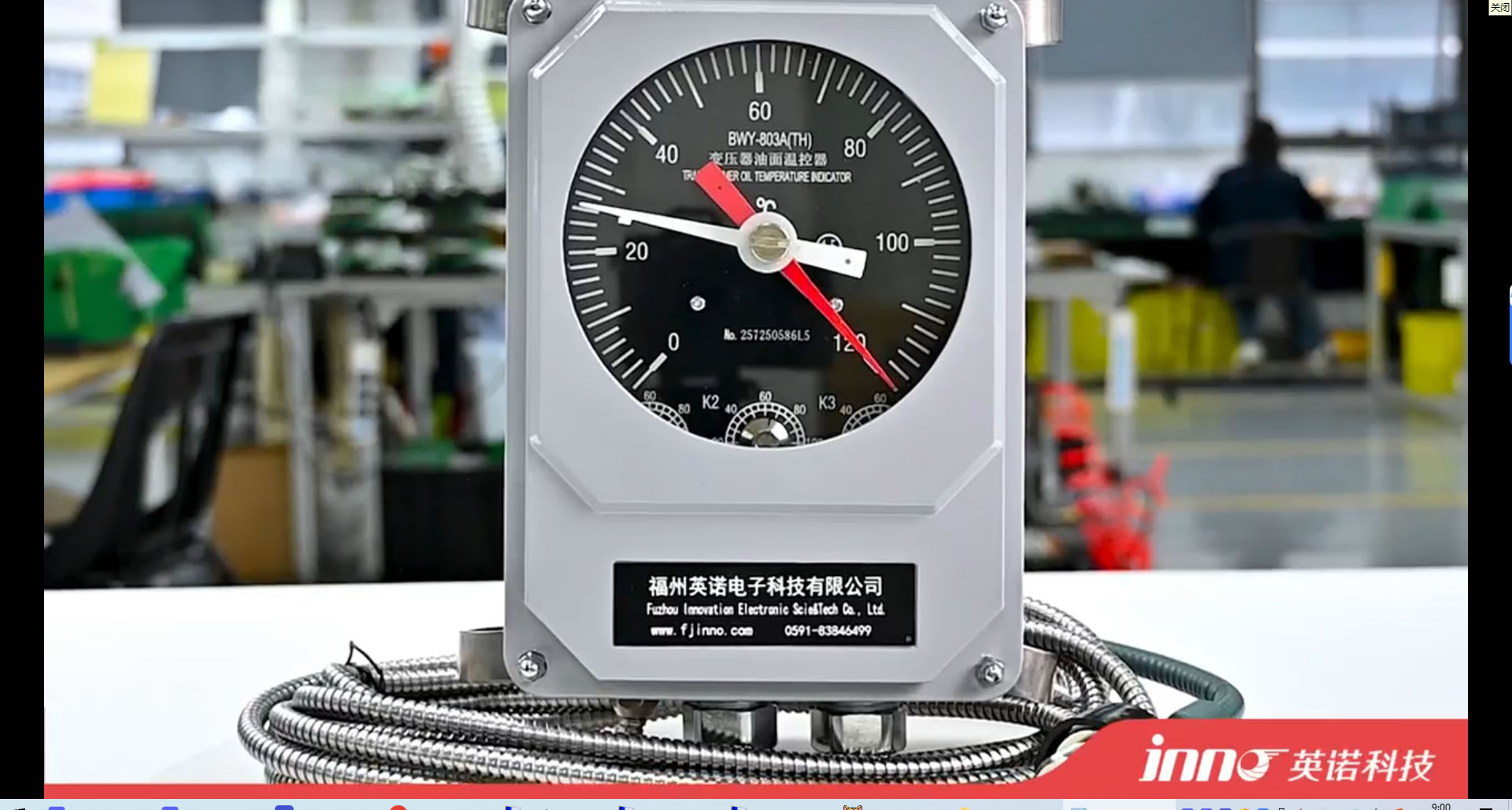
Oil Temperature Indicator Overview
Oil immersed transformer winding temperature controller oil temperature sensor
 E-mail: web@fjinno.net
WhatsApp: +8613599070393
WeChat(China): +8613599070393
- The oil temperature indicator (OTI) is a specialized device designed to monitor, display, and often control the temperature of insulating oil in transformers, engines, and various heavy-duty machinery.
- In power transformers, the OTI serves as a critical safety and diagnostic tool, protecting the transformer from overheating by providing real-time temperature readings and activating alarms or trips if necessary.
- OTIs are also commonly found in automotive systems, where they track engine or transmission oil temperatures to ensure optimal lubrication and prevent mechanical failure.
- Modern oil temperature indicators may include analog dials, digital displays, or remote communication capabilities, depending on application requirements and integration needs.
- A high-quality OTI not only safeguards expensive equipment but also supports effective preventive maintenance, data logging, and operational decision-making.
Table of Contents
- What is the Function of Oil Temperature Indicator?
- What Does Oil Temperature Indicate?
- What is AT Oil Temp Indicator?
- What is the Temperature Indicator in a Transformer?
- Transformer Oil Temperature Indicator
- Oil Temperature Indicator in Car
- Winding Temperature Indicator
- Winding Temperature Indicator Working Principle
- Qualitrol Winding Temperature Gauge
- Qualitrol Winding Temperature Gauge Manual
- Winding Temperature Indicator in Transformer
- Qualitrol Temperature Gauge Wiring Diagram
- Installation and Calibration of Oil Temperature Indicators
- Maintenance and Troubleshooting of Oil Temperature Indicators
- Future Trends in Oil Temperature Measurement Technology
What is the Function of Oil Temperature Indicator?
- Continuous Monitoring:
The oil temperature indicator’s primary function is to provide continuous, real-time monitoring of the oil temperature within critical equipment such as transformers or engines. By offering a direct reading of the oil’s thermal state, the OTI allows operators to assess whether the equipment is operating within its safe design limits. This monitoring is essential for both normal operation and during periods of increased load or stress, where oil temperature may rise rapidly. - Protection Mechanism:
The OTI often incorporates built-in switches or relays that are set to activate alarms or trip circuits when oil temperature exceeds predetermined thresholds. This protective feature is vital for preventing catastrophic equipment failure caused by overheating. For instance, in power transformers, the OTI can trigger cooling fans or even disconnect the transformer from the network if the oil temperature becomes dangerously high. - Data Source for Diagnostics:
Beyond immediate protection, the OTI serves as a valuable data source for maintenance teams and asset managers. Historical temperature data gathered from the indicator can reveal trends indicating insulation degradation, insufficient cooling, or abnormal loading patterns. This information supports condition-based maintenance and helps optimize asset life and performance. - Operational Efficiency:
By ensuring that the equipment operates within optimal temperature ranges, oil temperature indicators contribute to energy efficiency and reduce the incidence of unscheduled outages. For industries where reliability is paramount, such as power generation and heavy industry, efficient OTI operation is a key factor in minimizing operational costs and maximizing uptime.
What Does Oil Temperature Indicate?
- Heat Dissipation Status:
Oil temperature is a direct indicator of how effectively heat generated within the equipment is being dissipated. In a transformer, for example, the oil absorbs and transports heat away from the windings and core, preventing insulation breakdown. If the oil temperature is within the expected range, it suggests that the cooling system is functioning properly and that the transformer is not under excessive thermal stress. - Load Conditions:
Fluctuations in oil temperature often correlate with changes in electrical load. A sudden rise in temperature may indicate a period of heavy loading, while a gradual increase over time could signal issues such as increased losses, internal faults, or declining cooling efficiency. By monitoring oil temperature, operators gain insight into the actual stress being placed on the equipment in real time. - Early Warning of Faults:
Abnormal oil temperature readings can serve as an early warning of internal faults or operational anomalies. For example, a rapid temperature spike may be the first sign of a short circuit, winding defect, or blocked coolant flow. Early detection enables maintenance teams to investigate and resolve issues before they escalate into failures. - Indicator of Equipment Health:
Long-term analysis of oil temperature trends helps determine the overall health and remaining life of the equipment. Consistently high oil temperatures accelerate insulation aging and can shorten equipment lifespan. Regularly reviewing temperature data is therefore a crucial part of asset management and reliability engineering.
What is AT Oil Temp Indicator?
- Automotive Transmission Monitoring:
The AT oil temp indicator is a specialized warning light or gauge found in vehicles equipped with automatic transmissions. “AT” stands for “Automatic Transmission.” Its primary function is to alert the driver when the transmission fluid temperature exceeds safe operational limits, which can occur during heavy towing, high-speed driving, or in hot weather conditions. - Significance for Vehicle Health:
Monitoring the temperature of automatic transmission oil is vital because excessive heat can degrade the fluid, leading to poor lubrication, increased wear, and ultimately, transmission failure. The AT oil temp indicator provides the driver with an early warning, allowing preventive action—such as stopping to let the transmission cool—before permanent damage occurs. - System Operation:
The AT oil temp indicator is connected to a temperature sensor placed within the transmission fluid circuit. When the sensor detects a temperature above the preset threshold, it signals the indicator on the dashboard to illuminate or display a warning message, ensuring immediate driver awareness. - Maintenance and Troubleshooting:
Frequent AT oil temp warnings may indicate underlying issues such as low fluid levels, restricted fluid flow, or a failing transmission cooler. Routine checks of fluid condition and adherence to manufacturer service schedules are essential for long-term transmission reliability and performance.
What is the Temperature Indicator in a Transformer?
- Definition and Purpose:
The temperature indicator in a transformer is an instrument dedicated to displaying the temperature of critical components, most commonly the transformer oil and winding hot-spot. This indicator is fundamental for transformer operations, as it helps operators monitor thermal performance and remain within prescribed safety margins. - Types of Indicators:
There are typically two main types of temperature indicators in transformers: the oil temperature indicator (OTI) and the winding temperature indicator (WTI). The OTI directly measures oil temperature, while the WTI either simulates or directly measures the winding hot-spot temperature. - Alarm and Trip Integration:
Both types of indicators are usually equipped with electrical contacts for alarm and trip purposes. When the monitored temperature exceeds predefined limits, the indicator can activate cooling systems, trigger alarms, or initiate transformer shutdown procedures to prevent thermal damage. - Data Utilization:
The information provided by the temperature indicators is used not only for immediate operational decisions but also for long-term asset health analysis, trending, and regulatory reporting. Modern indicators often support remote monitoring through SCADA or data acquisition systems.
Transformer Oil Temperature Indicator
- Operational Principle:
The transformer oil temperature indicator (OTI) is designed specifically to measure the temperature of the insulating oil at the hottest point, typically near the top of the main tank. It uses a bulb or sensor immersed in the oil, which may be connected via capillary tubing to an external dial gauge or, in digital models, to electronic readouts. This direct measurement ensures an accurate reflection of the transformer’s thermal condition, which is crucial for safe operation. - Protection and Control:
Most OTIs incorporate electrical contacts that can be set to trigger alarms, start cooling fans, or initiate transformer trips at preset temperature thresholds. These contacts ensure the transformer operates within safe temperature limits and provide a line of defense against overheating, which could otherwise result in insulation breakdown or catastrophic failure. - System Integration:
Modern OTIs often feature communication ports for integration with SCADA or remote monitoring systems. This allows for real-time data transmission, centralized alarm management, and logging of temperature excursions for later analysis. Remote access to oil temperature data supports predictive maintenance and rapid response to emerging issues. - Calibration and Maintenance:
Regular calibration is essential to maintain OTI accuracy. Most manufacturers provide procedures for field or laboratory calibration, and some offer self-diagnostics in digital models. Maintenance includes checking sensor placement, ensuring capillary integrity, and verifying the function of alarm/trip contacts to prevent false readings or missed warnings.
Oil Temperature Indicator in Car
- Purpose and Placement:
In automotive applications, the oil temperature indicator is typically found on the dashboard and is responsible for displaying the temperature of the engine oil or, in some models, the transmission or differential oil. The indicator provides drivers with real-time information about the lubrication system’s health and the engine’s thermal load. - Sensor Technology:
Automotive OTIs use temperature sensors—often thermistors or thermocouples—installed in the oil sump, transmission pan, or near the oil filter. These sensors convert the oil’s heat into electrical signals that are interpreted by the vehicle’s engine control unit (ECU) and displayed on the dashboard. - Significance for Reliability:
Monitoring oil temperature is crucial for vehicle reliability, especially during high-performance driving, towing, or in extreme climates. Elevated oil temperatures may indicate insufficient lubrication, impending engine damage, or cooling system failure. Prompt response to high readings can prevent engine seizures or excessive wear. - Advanced Features:
Some modern vehicles integrate oil temperature data into digital dashboards and onboard diagnostics (OBD), enabling customizable warnings and maintenance reminders. This integration supports proactive driving habits and prolongs engine life.
Winding Temperature Indicator
- Role in Transformers:
The winding temperature indicator (WTI) is a critical device in power transformers, used to display the estimated or directly measured temperature of the transformer winding hot-spot. This information is essential because winding insulation is the most vulnerable component to thermal aging and failure. - Measurement Techniques:
Traditional WTIs estimate winding temperature using a combination of top oil temperature and a simulated temperature rise based on transformer load current. Advanced WTIs, especially those using fiber optic sensors, provide direct, real-time hot-spot measurement, improving accuracy and enabling tighter protection settings. - Alarm and Trip Functions:
Like the OTI, the WTI is equipped with contacts for alarm and trip activation. These contacts are programmed to operate at temperatures just below the insulation’s maximum safe operating limit, ensuring that overload events or cooling failures are swiftly addressed. - Asset Management:
WTI data is vital for transformer health assessment, life expectancy modeling, and informing maintenance schedules. Consistently elevated winding temperatures may prompt load reduction, cooling system upgrades, or accelerated insulation testing.
Winding Temperature Indicator Working Principle
- Indirect Measurement:
The traditional WTI operates on the principle of simulating winding temperature by combining the measured top oil temperature with an additional heating element. This heater is powered proportionally to the transformer’s load current, mimicking the increase in winding temperature caused by electrical losses. The sum of the oil temperature and simulated rise is displayed as the hot-spot temperature. - Direct Measurement:
Advanced WTIs use fiber optic sensors embedded directly within the transformer windings. These sensors are immune to electromagnetic interference and provide a direct, real-time measurement of the actual hot-spot temperature. This method eliminates the estimation errors of indirect systems and enables more precise transformer protection. - Signal Processing:
For both types, the temperature signal is processed and used to actuate alarm or trip contacts if the hot-spot exceeds programmed thresholds. The output may also be transmitted to remote monitoring systems for real-time supervision and archiving. - Advantages:
The working principles of both indirect and direct WTIs ensure that transformer operation remains within safe thermal limits, supporting longer asset life and reducing risk of insulation failure.
FJINNO Winding Temperature Gauge
- Brand Overview:
FJINNO is a leading manufacturer of transformer monitoring equipment, including winding temperature gauges. Their WTIs are widely used in the power industry for reliable, precise, and robust temperature measurement and protection. - Product Features:
FJINNO WTIs are available in both analog and digital configurations. They offer direct or simulated hot-spot measurement, multiple alarm and trip contacts, and options for local and remote display. Some models support communication protocols for SCADA integration. - Installation and Compatibility:
FJINNO winding temperature gauges are designed for easy installation on a variety of transformer types and sizes. Their modular design allows for field upgrades, calibration, and integration with other Qualitrol monitoring solutions. - Industry Adoption:
Utilities and industrial operators worldwide rely on Qualitrol WTIs for transformer protection, maintenance planning, and regulatory compliance, due to their proven performance and strong technical support.
FJINNO Winding Temperature Gauge Manual
- Purpose and Scope:
The FJINNO winding temperature gauge manual is an essential resource for engineers, technicians, and maintenance staff responsible for installation, calibration, and operation of the gauge. It contains step-by-step instructions, safety guidelines, and troubleshooting tips. - Installation Procedures:
The manual details proper mounting of the gauge, wiring of alarm/trip contacts, and connection of sensor inputs. Special attention is given to routing of sensor cables, environmental protection, and avoidance of electromagnetic interference. - Calibration and Testing:
Comprehensive calibration procedures are provided to ensure that the gauge delivers accurate readings. The manual also explains how to test alarm and trip functions before placing the transformer into service. - Troubleshooting and Maintenance:
Users are guided through common troubleshooting scenarios, such as erratic readings or contact failures. Maintenance intervals, cleaning recommendations, and spare parts lists are included for long-term reliability.
Winding Temperature Indicator in Transformer
- Critical Monitoring Point:
In power transformers, the winding temperature indicator is positioned as one of the most vital protective devices. It is specifically tasked with measuring or simulating the hottest spot within the winding, which is where insulation aging occurs most rapidly. By providing an accurate readout of this temperature, the WTI acts as a direct safeguard against thermal overstress and premature transformer failure. - Integration with Protection Systems:
The WTI is typically integrated with the transformer’s protection relay system. If the winding temperature exceeds the pre-set alarm or trip values, it triggers warnings, starts forced cooling, or even disconnects the transformer from service. This integration ensures that abnormal thermal conditions are immediately addressed, reducing the risk of major faults or fire. - Dual Role—Display and Data Source:
Besides its protective function, the WTI provides valuable operational data. Its display allows operators to monitor transformer loading and cooling effectiveness in real time. Meanwhile, modern WTIs with digital output can transmit temperature data to SCADA or asset management systems, supporting trend analysis and predictive maintenance strategies. - Calibration and Reliability:
Precise calibration is essential for WTI reliability. Manufacturers supply calibration procedures and recommend regular checks to ensure the indicator remains within specification. Proper maintenance of the indicator, sensors, and associated wiring is also crucial for long-term transformer safety.
FJINNO Temperature Gauge Wiring Diagram
- Basic Wiring Components:
The FJINNO temperature gauge wiring diagram details the connections between the sensor (often an RTD or thermistor), the gauge itself, and associated alarm or trip contacts. It illustrates how to link the sensor’s output to the gauge’s input terminals, ensuring accurate temperature measurement. - Alarm and Trip Connections:
The diagram also shows the wiring for the electrical contacts used to activate alarms or initiate protective trips. These contacts are typically connected to control relays, SCADA systems, or cooling fan starters. The correct configuration allows for staged responses as temperature thresholds are crossed. - Power Supply and Grounding:
Proper power supply wiring is critical for reliable operation. The diagram specifies voltage requirements, fuse ratings, and grounding points to avoid electrical noise and ensure safety. Incorrect wiring can lead to false alarms, missed trips, or gauge failure. - Best Practices:
The manual recommends using shielded cables, secure connections, and appropriate conduit for all wiring. It also highlights the importance of verifying wiring integrity during installation and as part of routine maintenance.
Installation and Calibration of Oil Temperature Indicators
- Site Preparation:
Prior to installation, the mounting location for the oil temperature indicator must be assessed for accessibility, minimal vibration, and proximity to the hottest point in the oil (usually the top of the transformer tank or engine sump). Environmental factors such as moisture, dust, and electromagnetic fields should be considered to protect the indicator and wiring. - Physical Installation:
The sensor bulb or probe is carefully immersed in the oil at the designated location. For capillary-based indicators, the capillary tube is routed securely to the external dial or digital display, avoiding sharp bends and mechanical stress. For electronic sensors, wiring is run through protective conduit to the indicator module. - Wiring and Connections:
Power supply, sensor input, and alarm/trip outputs are all connected according to the manufacturer’s wiring diagram. All terminal connections are double-checked for tightness, insulation, and correct polarity. Shielded cables are used when necessary to prevent electrical interference. - Calibration Procedure:
Calibration is performed using a reference temperature source, such as a calibrated thermometer or temperature bath. The indicator is adjusted to match the reference reading at several points across its range. For digital indicators, software calibration may be available. Calibration data is documented for quality assurance and future audits.
Maintenance and Troubleshooting of Oil Temperature Indicators
- Routine Inspection:
Periodic inspection is essential to ensure reliable OTI performance. This includes visual checks for physical damage, oil leaks at sensor entry points, and integrity of wiring or capillary tubes. The indicator’s display and alarm functionality are also verified regularly. - Functional Testing:
Alarm and trip contacts are tested by simulating high oil temperatures, either with a heat gun or by adjusting the setpoint temporarily. This confirms that protective functions will operate correctly in an emergency. - Common Issues and Solutions:
Typical problems include erratic readings caused by sensor degradation, false alarms due to wiring faults, or stuck pointers in analog gauges. Troubleshooting involves isolating the faulty component—sensor, wiring, or indicator—and replacing or recalibrating as needed. - Documentation and Record Keeping:
All maintenance and calibration activities are logged, including test results and any parts replaced. This documentation supports compliance with operational standards and helps identify recurring issues for long-term improvement.
Future Trends in Oil Temperature Measurement Technology
- Digitalization and Connectivity:
The future of oil temperature indicators lies in digitalization, with increasing adoption of smart sensors and networked indicators. These devices support remote monitoring, automated data logging, and integration with advanced asset management systems. Operators can access real-time temperature data from anywhere, improving response times and operational transparency. - Advanced Sensing Technologies:
Innovations such as fiber optic temperature sensing, infrared measurement, and wireless sensor networks are enhancing accuracy and reliability. These technologies are especially valuable in high-voltage or high-EMI environments where traditional sensors may struggle. - Predictive Analytics:
The integration of temperature data with AI-based analytics enables predictive maintenance, anomaly detection, and remaining life estimation for transformers and engines. This shift allows operators to move from reactive to proactive maintenance strategies, reducing costs and improving reliability. - Enhanced User Experience:
Future indicators will feature more intuitive interfaces, customizable alarms, and self-diagnostic capabilities. Touchscreen displays, wireless alerts, and automated calibration routines will make temperature monitoring easier and more accurate for both field and remote personnel.

Fiber optic temperature sensor, Intelligent monitoring system, Distributed fiber optic manufacturer in China
 |
 |
 |