 INNO fibre optic temperature sensors ,temperature monitoring systems.
- ✓ Two Main Technologies: Distributed Temperature Sensing (DTS) for continuous monitoring + Point-type fluorescence sensors for discrete precision
- ✓ Key Advantages: Complete EMI immunity, intrinsically safe, ±0.3°C to ±1°C accuracy, maintenance-free 20-30 years
- ✓ Temperature Range: -200°C to +300°C covering all industrial applications
- ✓ DTS Capabilities: 0-30km continuous monitoring, 1-3m spatial resolution, ideal for cables and pipelines
- ✓ Point Sensors: 4-64 channel systems, 0.5-80m fiber lengths, <1 second response for transformers and switchgear
- ✓ Applications: Power transformers, cables, oil/gas facilities, industrial manufacturing, data centers
- ✓ Manufacturer: Fuzhou Innovation – specialized fiber optic temperature solutions since 2011
- ✓ Integration: 4-20mA, RS485, Ethernet, IEC 61850 for seamless SCADA connectivity
Fiber optic solutions for temperature monitoring represent the most reliable and accurate technology for industrial temperature measurement, utilizing both distributed temperature sensing (DTS) systems for continuous spatial coverage and point-type fiber optic temperature sensors for discrete high-precision applications. As a specialized manufacturer of fiber optic temperature monitoring systems, Fuzhou Innovation Electronic Scie&Tech Co., Ltd. delivers complete solutions serving power utilities, oil/gas facilities, industrial plants, and critical infrastructure worldwide since 2011.
Table of Contents
- What Are Fiber Optic Solutions for Temperature Monitoring?
- How Do Fiber Optic Temperature Sensors Work?
- Why Choose Fiber Optic Temperature Monitoring Solutions?
- What Are the Two Main Types of Solutions?
- What Are Distributed Temperature Sensing (DTS) Solutions?
- What Are Point-Type Fiber Optic Temperature Sensors?
- What Industrial Applications Use These Solutions?
- How to Monitor Power Transformers?
- How to Monitor Power Cables with DTS?
- What Are the Technical Specifications?
- How to Integrate with Control Systems?
- What Installation Methods Exist?
- How to Select the Right Solution?
- What Are the Advantages Over Traditional Sensors?
- How Much Does It Cost?
- What Certifications and Standards Apply?
- What Customization Options Are Available?
- Frequently Asked Questions
- Who Is The Leading Manufacturer?
- How to Contact for Solutions?
1. What Are Fiber Optic Solutions for Temperature Monitoring?

What are they? Fiber optic solutions for temperature monitoring encompass advanced measurement technologies using optical fiber and light-based sensing principles to detect temperature with superior accuracy, reliability, and safety compared to traditional electrical sensors. The technology divides into two complementary categories: distributed temperature sensing (DTS) systems providing continuous spatial temperature profiles along fiber lengths up to 30km, and point-type fiber optic temperature sensors offering discrete high-precision measurements at specific locations.
Why Choose Fiber Optic Over Traditional Methods?
Fiber optic temperature monitoring fundamentally differs from resistance temperature detectors (RTDs), thermocouples, or infrared sensors by using light transmission through glass fiber rather than electrical signals. This optical approach eliminates electromagnetic interference (EMI) susceptibility, provides intrinsic electrical isolation for high-voltage safety, operates without electrical power at sensing points, and requires zero maintenance throughout 20-30 year service life.
Two Core Technology Types
Distributed Temperature Sensing (DTS): Transforms entire optical fiber into thousands of temperature sensors spaced every 1-3 meters along lengths up to 30km. Ideal for continuous monitoring applications like power cable tunnels, pipeline temperature profiling, and perimeter security where spatial temperature distribution provides critical operational intelligence.
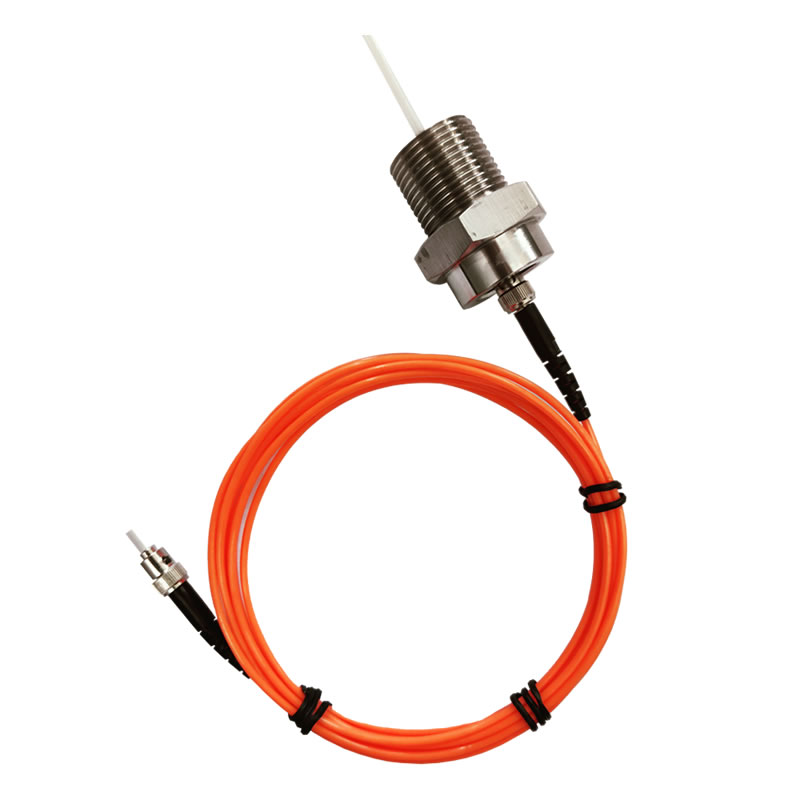
Point-Type Fluorescence Sensors: Provides precision temperature measurement at discrete locations with ±0.3°C to ±1°C accuracy and <1 second response time. Configured as multi-channel systems (4-64 channels), these sensors excel at applications requiring precise monitoring of specific hot spots like transformer windings, switchgear bus bars, motor bearings, or semiconductor processing equipment.
Core Value Proposition
The fundamental value of fiber optic temperature sensing lies in combining measurement excellence with operational advantages: complete EMI immunity prevents false readings in electrically noisy industrial environments, intrinsically safe operation eliminates explosion risks in hazardous areas, maintenance-free operation reduces lifecycle costs, and stable accuracy without calibration drift ensures reliable long-term performance.
2. How Do Fiber Optic Temperature Sensors Work?
How does the technology operate? Fiber optic temperature sensing employs fundamentally different physical principles depending on whether distributed or point-type measurement is required.
Distributed Temperature Sensing (DTS) Operating Principle
Raman Scattering Phenomenon
Distributed fiber optic temperature sensing utilizes Raman scattering—when laser light travels through optical fiber, molecular vibrations cause a small fraction to scatter back at shifted wavelengths. This backscattered light contains two components: Stokes (longer wavelength) and anti-Stokes (shorter wavelength). The anti-Stokes intensity depends strongly on temperature while Stokes remains relatively stable, creating a temperature-dependent intensity ratio.
Optical Time Domain Reflectometry (OTDR)
DTS systems determine temperature location using OTDR principles. By transmitting short laser pulses and measuring the time delay of backscattered light, the system calculates distance to each sensing point. Combining time-resolved measurements with Raman intensity analysis, DTS temperature monitoring creates continuous temperature profiles showing exact temperature at every meter along the fiber.
Continuous Measurement Process
The interrogator unit continuously sends laser pulses (typically every 5-60 seconds depending on configuration), analyzes returning Raman scatter from thousands of fiber segments simultaneously, calculates temperature at each location, and displays the complete spatial temperature profile. This process repeats continuously, providing real-time temperature monitoring across the entire fiber length.
Point-Type Fluorescence Sensor Operating Principle

Fluorescence Lifetime Measurement
Fiber optic temperature sensors using fluorescence technology employ rare-earth phosphor materials at the fiber tip. When excited by LED light transmitted through the fiber, these materials emit fluorescence that decays exponentially. The decay time (typically measured in microseconds) changes predictably with temperature—higher temperatures produce faster decay, lower temperatures slower decay.
Temperature-Decay Time Relationship
The sensor interrogator measures fluorescence decay time with high precision by pulsing the excitation LED, capturing the fluorescence emission, analyzing the exponential decay curve, and converting decay time to temperature using factory calibration. This measurement principle depends on fundamental atomic physics that remains stable indefinitely, eliminating calibration requirements.
Why Fluorescence Ensures Accuracy
Unlike electrical sensors where resistance or voltage changes with component aging, fiber optic temperature measurement using fluorescence decay depends on unchanging quantum mechanical properties of rare-earth materials. The phosphor crystal structure remains chemically stable across temperature cycles, mechanical stress, and environmental exposure, maintaining consistent decay time-temperature relationship throughout the sensor’s 20+ year lifetime.
3. Why Choose Fiber Optic Temperature Monitoring Solutions?
Why are fiber optic solutions superior? Fiber optic temperature monitoring systems deliver compelling advantages over traditional electrical sensors across technical performance, safety, reliability, and total cost of ownership.
Complete Electromagnetic Interference (EMI) Immunity
Glass fiber transmits light signals completely unaffected by electromagnetic fields. In environments with high-voltage equipment, variable frequency drives, radio transmitters, or welding operations, electrical sensors produce measurement errors of ±5-10°C or complete failure. Optical fiber temperature sensors maintain accurate readings regardless of EMI intensity, eliminating false alarms and ensuring reliable monitoring in electrically hostile industrial environments.
Intrinsically Safe Operation
Fiber optic temperature sensing provides ultimate safety in explosive atmospheres. The sensing fiber contains no electrical conductors, generates no heat, produces no sparks, and cannot ignite flammable gases or dust. This intrinsic safety eliminates requirements for explosion-proof enclosures at measurement points, reduces installation costs, and enables deployment in hazardous classified areas (Class I Division 1, ATEX Zone 0) where electrical sensors require extensive protection measures.
High Measurement Accuracy
Point-type fiber optic temperature sensors achieve ±0.3°C to ±1°C accuracy with 0.1°C resolution, while distributed temperature sensing systems provide ±1°C accuracy across -200°C to +300°C range. This precision enables detection of subtle temperature variations indicating developing problems hours or days before failure, supporting predictive maintenance strategies that prevent unplanned outages.
Wide Temperature Range Coverage
Fiber optic temperature measurement systems operate across extreme temperature ranges:
- Cryogenic applications: -200°C for liquefied gas monitoring, superconducting equipment, research facilities
- Ambient monitoring: -40°C to +85°C for transformers, switchgear, industrial process equipment
- High temperature: +200°C to +300°C for furnaces, kilns, hot oil systems, exhaust monitoring
Single sensor technology covers this entire range without multiple sensor types or special configurations.
Maintenance-Free Long Service Life
Glass optical fiber temperature sensors require zero maintenance throughout 20-30 year operational lifetime. No calibration checks, no battery replacements, no periodic verification—once installed, the system operates reliably until equipment end-of-life. Solid-state interrogator electronics similarly operate maintenance-free with no moving parts or consumables.
Corrosion and Chemical Resistance
Glass fiber is chemically inert, unaffected by moisture, oils, solvents, acids, or alkaline environments that corrode electrical sensor components. Fiber optic temperature monitoring operates reliably in transformer oil, chemical process fluids, marine environments, or outdoor installations where traditional sensors require frequent replacement.
Multi-Point and Continuous Monitoring
Point-type systems support 4-64 channels from single interrogator, while distributed temperature sensing provides thousands of measurement points along one fiber. This dense monitoring capability detects localized hot spots that discrete point sensors spaced at wide intervals would miss, providing comprehensive temperature surveillance impossible with conventional approaches.
4. What Are the Two Main Types of Fiber Optic Temperature Solutions?
What is the difference between distributed and point sensing? Understanding the distinction between distributed temperature sensing (DTS) and point-type fiber optic temperature sensors guides proper technology selection for specific applications.
Distributed Temperature Sensing (DTS) Systems
Technology Characteristics
Distributed fiber optic temperature sensing transforms the entire optical fiber into a continuous temperature sensor. Every meter of fiber becomes a measurement point, creating spatial temperature profiles showing temperature at each location along lengths up to 30km. The system displays results as temperature-versus-distance graphs revealing hot spots, temperature gradients, and thermal patterns across the monitored asset.
Key Specifications
- Monitoring distance: 0-30km single-end, 40-50km dual-end configuration
- Spatial resolution: 1-3m (defines measurement point spacing)
- Temperature accuracy: ±1°C across full range
- Measurement time: 5-60 seconds per complete profile
- Temperature range: -200°C to +300°C
Ideal Applications
DTS excels where continuous spatial coverage is critical: power cable tunnel monitoring detecting hot spots anywhere along kilometers of cable routes, pipeline temperature profiling for leak detection or flow assurance, perimeter security systems detecting intrusion through thermal signatures, or fire detection in tunnels, warehouses, and conveyor systems.
Point-Type Fiber Optic Temperature Sensors
Technology Characteristics
Point-type fiber optic temperature sensors measure temperature at discrete locations using fluorescence decay principles. Each sensor probe connects via optical fiber (0.5-80m length) to a multi-channel interrogator. Systems configure as 4, 8, 12, 16, 32, or 64 channels, with each channel providing independent high-precision measurement.
Key Specifications
- Temperature accuracy: ±0.3°C to ±1°C depending on range
- Response time: <1 second for 63% of step change
- Fiber length: 0.5-80 meters per channel without signal degradation
- Channel count: 4/8/12/16/32/64 channels per interrogator
- Temperature range: -40°C to +260°C standard, extended ranges available
Ideal Applications
Point sensors suit applications requiring precise measurement at known critical locations: transformer winding hot spots (3 sensors per winding phase), switchgear bus bar connections, motor bearing temperatures, semiconductor wafer processing, or any application where specific measurement points are predetermined and high accuracy is essential.
Technology Comparison
| Feature | DTS Systems | Point-Type Sensors |
|---|---|---|
| Coverage Type | Continuous along entire fiber | Discrete measurement points |
| Measurement Points | Thousands (every 1-3m) | 4-64 specific locations |
| Accuracy | ±1°C | ±0.3°C to ±1°C |
| Response Time | 5-60 seconds | <1 second |
| Monitoring Distance | 0-30km per interrogator | 0.5-80m per channel |
| Best For | Linear assets (cables, pipelines) | Equipment monitoring (transformers, motors) |
| Hot Spot Detection | Detects anywhere along fiber | Monitors predetermined locations |
| Installation Complexity | Moderate (long fiber routing) | Simple (direct sensor placement) |
How to Choose Between Technologies
Select DTS when monitoring linear assets where hot spots could develop anywhere (cables, pipelines), when spatial temperature distribution provides operational intelligence (process heating/cooling), or when monitoring inaccessible locations (buried cables, underwater pipelines).
Select point sensors when monitoring specific known critical points (transformer windings, switchgear connections), when faster response than DTS is required (<1 second), when highest accuracy is essential (±0.3°C), or when monitoring compact equipment where DTS’s long fiber runs are impractical.
5. What Are Distributed Temperature Sensing (DTS) Solutions?

How does distributed temperature sensing work? DTS temperature monitoring systems provide comprehensive spatial temperature surveillance for applications requiring continuous coverage along extended linear assets.
DTS System Architecture
Complete distributed temperature sensing system includes:
- DTS interrogator unit: Laser source, optical detection, signal processing electronics analyzing Raman backscatter
- Sensing fiber cable: Standard or specialized optical fiber installed along monitored asset
- Data acquisition system: Computer with DTS software for visualization, alarming, and data logging
- Communication interface: Ethernet, RS485, MODBUS for SCADA integration
- Power supply: 12-36VDC or 110/220VAC depending on model
Technical Performance Parameters
| Parameter | Specification | Application Note |
|---|---|---|
| Measurement Distance | 0-30km single-end | 40-50km dual-end |
| Spatial Resolution | 1-3m typical | Adjustable based on range |
| Sampling Interval | 1m | Data point every meter |
| Temperature Accuracy | ±1°C | Across full measurement range |
| Temperature Resolution | 0.1°C | Detects subtle changes |
| Measurement Time | 5-60 seconds | User configurable |
| Temperature Range | -200°C to +300°C | Covers all industrial needs |
| Fiber Type | Multimode 50/125 or 62.5/125 | Standard telecom fiber |
| Channels | 1/2/4/8 independent zones | Monitor multiple assets |
Key Advantages of DTS
Comprehensive Spatial Coverage
Distributed fiber optic temperature sensing eliminates monitoring blind spots. Unlike point sensors measuring every 100m or 1km, DTS provides temperature data every meter along the entire cable length. Hot spots developing anywhere trigger immediate detection and precise location identification.
Long-Distance Capability
Single interrogator monitors up to 30km from one location, reducing equipment count and installation costs. Dual-end configuration extends range to 40-50km with improved accuracy through averaging measurements from both directions.
Real-Time Continuous Monitoring
Systems update complete temperature profiles every 5-60 seconds (user configurable), providing near-real-time surveillance. Operators view temperature-versus-distance graphs showing thermal conditions across the entire monitored asset with historical trending revealing gradual degradation patterns.
6. What Are Point-Type Fiber Optic Temperature Sensors?
How do fluorescence-based fiber optic sensors work? Point-type fiber optic temperature sensors using fluorescence decay technology deliver precision temperature measurement at discrete locations requiring high accuracy and fast response.
Fluorescence Sensing Technology
The sensor probe contains rare-earth phosphor crystal (typically GaAs-based material) at the fiber tip. LED light transmitted through the optical fiber excites the phosphor, causing fluorescence emission that travels back through the fiber to the interrogator. The fluorescence decays exponentially with a time constant (typically 1-100 microseconds) that changes predictably with temperature. By measuring this decay time with nanosecond precision, the system calculates temperature with exceptional accuracy.
Technical Performance Specifications
| Parameter | Specification | Application Note | ||||||||||||
|---|---|---|---|---|---|---|---|---|---|---|---|---|---|---|
| Temperature Accuracy | ±0.3°C to ±1°C | Depends on temperature range | ||||||||||||
| Temperature Resolution | 0.1°C | Sensitive change detection | ||||||||||||
| Response Time | <1 second (63% step) | Fast thermal tracking | ||||||||||||
| Temperature Range | -40°C to +260°C standard | Fiber Length | 0.5m to 80m per channel | No signal degradation | Channel Count | 4/8/12/16/32/64 channels | Flexible configurations | Sensor Probe Size | 2-4mm diameter typical | Compact for tight spaces | Service Life | 20+ years | Maintenance-free operation |
Unique Advantages of Point Sensors
Superior Accuracy
Fiber optic temperature sensors achieve ±0.3°C to ±1°C accuracy maintained throughout 20+ year lifetime without calibration. This precision enables detection of subtle temperature rises indicating developing problems, supporting predictive maintenance strategies preventing unplanned outages.
Fast Response Time
Sub-second response (<1 second for 63% of step change) enables rapid detection of thermal events. Critical for applications requiring immediate alarm response like transformer overload protection or motor bearing failure detection.
Flexible Installation
Fiber lengths from 0.5-80 meters enable remote sensing where measurement points are physically separated from interrogator location. Multiple sensors connect to single interrogator, reducing equipment count and installation complexity.
Complementary to DTS
While DTS provides spatial overview, point-type optical fiber temperature sensors add precision measurement at critical locations. Combined systems leverage both technologies—DTS for general surveillance plus point sensors at known hot spots requiring highest accuracy.
7. What Industrial Applications Use Fiber Optic Temperature Monitoring?
Where are fiber optic temperature solutions deployed? Fiber optic temperature monitoring systems serve diverse industrial sectors requiring reliable, accurate, and safe temperature measurement.
Power Industry Applications
Transformer Winding Temperature Monitoring
Fiber optic temperature sensors embedded in transformer windings provide direct hot spot measurement impossible with traditional oil temperature indicators. Standard 12-channel configuration monitors 3 sensors per high-voltage winding phase, 3 per low-voltage winding phase, plus oil and core temperatures. This comprehensive monitoring prevents insulation degradation and extends transformer life by 30-50%.
Switchgear Bus Bar Monitoring
High-current bus bar connections generate heat from contact resistance. Point-type fiber optic temperature sensors mounted on bus bars detect overheating from loose connections, corrosion, or overload conditions. Complete EMI immunity ensures accurate readings in high-voltage electromagnetic fields where electrical sensors fail.
Power Cable Temperature Monitoring
Distributed temperature sensing along power cable routes detects hot spots from overload, insulation degradation, or poor joints. Cable tunnel installations use fiber attached to tunnel walls or strapped directly to cables, providing continuous thermal surveillance across kilometers of cable runs with 1-3m spatial resolution identifying exact problem locations.
Generator Stator Winding Monitoring
Generator stator windings operate at high temperatures requiring precise monitoring. Fiber optic temperature measurement provides EMI-immune sensing in intense magnetic and electromagnetic fields surrounding rotating machinery, enabling reliable temperature tracking impossible with electrical sensors.
Oil & Gas Industry Applications
Pipeline Temperature Profiling
DTS temperature monitoring tracks pipeline thermal conditions for leak detection, flow assurance, and operational optimization. Temperature anomalies indicate leaks (cooling from pressure drop), wax deposition (reduced heat transfer), or insulation degradation. Systems monitor pipelines up to 30km per interrogator with dual-end configurations extending to 50km.
Storage Tank Temperature Distribution
Vertical temperature profiling in storage tanks detects stratification, heating system performance, and product quality issues. Fiber cables installed vertically measure temperature at multiple heights, revealing thermal gradients affecting product specifications or indicating tank heating problems.
Reactor and Vessel Monitoring
Chemical reactors require precise temperature control for safety and product quality. Fiber optic temperature sensing provides intrinsically safe measurement in explosive atmospheres, with sensors placed at multiple reactor zones tracking temperature distribution and detecting runaway reaction conditions.
Fired Heater Tube Monitoring
Distributed fiber optic temperature sensing along heater tubes detects hot spots from coking or flow maldistribution. Early detection prevents tube failure and unplanned shutdowns in critical process equipment.
Industrial Manufacturing Applications
Induction Heating Equipment
Induction heating systems generate intense electromagnetic fields defeating electrical sensors. Fiber optic temperature monitoring operates unaffected by EMI, providing reliable temperature measurement for process control and equipment protection.
Heat Treatment Furnaces
Precise temperature control in heat treatment processes ensures metallurgical properties. Fiber optic temperature sensors withstand high temperatures and provide accurate measurement for quality assurance and process optimization.
Injection Molding Mold Monitoring
Mold temperature affects part quality in plastic injection molding. Multi-channel fiber optic temperature measurement systems monitor temperature at multiple mold locations, enabling precise thermal control for consistent part production.
Semiconductor Process Equipment
Semiconductor manufacturing requires precise temperature control with EMI immunity. Fiber optic temperature sensors monitor wafer processing, diffusion furnaces, and CVD reactors without introducing contamination or electromagnetic interference.
Infrastructure Applications
Tunnel Fire Detection
DTS systems detect fires in road tunnels, rail tunnels, and utility tunnels by monitoring temperature continuously. Rapid temperature rise triggers alarms with precise fire location, enabling targeted fire suppression and emergency response.
Data Center Thermal Management
Data centers use distributed temperature sensing along server racks and under raised floors, detecting hot spots from cooling failures or airflow problems. Real-time thermal mapping optimizes cooling efficiency and prevents equipment overheating.
Subway Cable Tunnel Monitoring
Metro systems install fiber optic temperature monitoring in cable tunnels for fire detection and cable thermal surveillance. Continuous monitoring detects overload conditions or developing fires before smoke reaches detection systems.
Building Fire Detection
Linear heat detection using DTS provides continuous fire surveillance in warehouses, parking garages, conveyor systems, and industrial facilities. Fiber cable installed along ceilings or in cable trays detects fire anywhere along its length.
8. How to Monitor Power Transformers with Fiber Optic Solutions?
![]()
Why do transformers need fiber optic temperature monitoring? Power transformers represent critical high-value assets where failure causes extended outages and replacement costs exceeding millions of dollars. Temperature monitoring provides essential protection and life extension.
Why Transformer Temperature Monitoring is Critical
Transformer failures develop from insulation degradation accelerated by excessive temperature. Every 8-10°C temperature increase above rated levels halves insulation life through accelerated aging. Without direct winding monitoring, internal hot spots reach destructive levels while external indicators show acceptable temperatures. Fiber optic temperature sensors embedded in windings detect actual hot spot temperatures, enabling protective action before damage occurs.
Standard 12-Channel Transformer Monitoring Configuration
Comprehensive transformer monitoring requires strategic sensor placement:
- High-voltage winding: 3 sensors (one per phase) at winding hot spot locations
- Low-voltage winding: 3 sensors (one per phase) at winding hot spot locations
- Iron core: 1 sensor monitoring core temperature
- Top oil temperature: 2 sensors measuring oil temperature in tank
- Optional sensors: Tap changer, bushing connections, cooling system
Typical Monitoring Points and Alarm Thresholds
| Location | Normal Range | Alarm Threshold | Trip Threshold |
|---|---|---|---|
| Winding Hot Spot | 60-80°C | 95°C | 110°C |
| Top Oil Temperature | 40-70°C | 85°C | 95°C |
| Iron Core | 50-75°C | 90°C | 100°C |
| Tap Changer | 45-65°C | 80°C | 90°C |
Advantages Over Traditional Pt100 RTD Sensors
| Feature | Fiber Optic Sensors | Pt100 RTD |
|---|---|---|
| EMI Immunity | Complete immunity | ±5-10°C errors from interference |
| High Voltage Safety | Inherently safe, no isolation needed | Requires complex isolation barriers |
| Calibration | Never required | Every 2 years |
| Service Life | 20+ years | 5-10 years |
| Accuracy Stability | ±1°C for life | Drifts over time |
| Oil Compatibility | Unaffected by oil | Degradation from oil exposure |
| Lightning Protection | No protection needed | Requires surge protection |
9. How to Monitor Power Cables with Fiber Optic DTS?
How does DTS monitor cable temperature? Distributed temperature sensing provides continuous thermal surveillance of power cable systems, detecting problems before they cause failures.
Cable Temperature Monitoring Applications
Underground Cable Tunnels
Cable tunnels house multiple high-voltage cables in confined spaces where cooling is critical. DTS systems with fiber attached to tunnel walls or laid along cable routes monitor temperature continuously, detecting hot spots from cable overload, poor joints, insulation degradation, or ventilation failures.
Direct Buried Cables
Fiber cables buried alongside power cables monitor soil temperature indicating cable thermal conditions. Hot spots reveal cable problems or variations in thermal backfill conditions affecting cable capacity.
Cable Trays and Ducts
Fiber installed in cable trays or pulled through ducts provides continuous temperature monitoring. Systems detect overloaded circuits, failing joints, or environmental issues affecting cable thermal performance.
Fiber Installation Methods
- Helical wrapping: Fiber cable spiraled around power cable exterior for direct thermal contact
- Parallel installation: Fiber laid alongside cables in tunnels or ducts
- Wall mounting: Fiber attached to tunnel walls near cable routes
- Integrated cables: Some power cables include built-in optical fibers
Hot Spot Detection and Location
Distributed fiber optic temperature sensing identifies exact problem locations. Temperature profiles show normal baseline with anomalous peaks at hot spot locations. The system displays hot spot temperature, position (distance from DTS unit), and severity, enabling maintenance crews to locate and repair problems quickly.
Dynamic Cable Rating
Cable ampacity depends on operating temperature. DTS temperature monitoring enables real-time ampacity calculation based on actual measured temperatures rather than conservative design assumptions. This dynamic rating increases usable cable capacity by 10-30% without risking damage, maximizing infrastructure investment.
Fire Early Warning
Rapid temperature rise in cable tunnels indicates fire conditions. DTS systems trigger alarms when temperature exceeds thresholds or rises at abnormal rates, providing early fire detection before smoke reaches conventional sensors. Precise fire location enables targeted suppression response.
10. What Are the Technical Specifications of Fiber Optic Temperature Systems?
What specifications should you consider? Understanding technical parameters ensures proper fiber optic temperature monitoring system selection and specification.
DTS System Specifications
| Parameter | Typical Value | Notes |
|---|---|---|
| Fiber Type | Multimode 50/125 or 62.5/125 μm | Standard telecom fiber |
| Measurement Range | 0-30km single-end, 40-50km dual-end | Configurable |
| Channels | 1/2/4/8 independent zones | Multi-zone monitoring |
| Spatial Resolution | 1-3m | Adjustable with range |
| Sampling Interval | 1m | Data point spacing |
| Temperature Accuracy | ±1°C | Full range |
| Temperature Resolution | 0.1°C | Change detection |
| Temperature Range | -200°C to +300°C | Application dependent |
| Measurement Time | 5-60 seconds | User configurable |
| Optical Connector | FC/APC or SC/APC | Low back-reflection |
Point-Type Sensor System Specifications
| Parameter | Typical Value | Notes |
|---|---|---|
| Channel Count | 4/8/12/16/32/64 channels | Modular expansion |
| Temperature Accuracy | ±0.3°C to ±1°C | Range dependent |
| Temperature Resolution | 0.1°C | Display resolution |
| Response Time | <1 second | 63% of step change |
| Temperature Range | -40°C to +260°C | Standard range |
| Fiber Length | 0.5m to 80m per channel | No signal loss |
| Sensor Probe Diameter | 2-4mm | Compact design |
| Optical Connector | FC or ST | Standard connectors |
System Interface and Power Specifications
| Parameter | Specification |
|---|---|
| Power Supply | 12-36VDC or 110/220VAC |
| Power Consumption | 8-50W depending on model |
| Operating Temperature | 0-40°C |
| Storage Temperature | -20°C to -60°C |
| Operating Humidity | 0-95%RH, non-condensing |
| Communication Interfaces | 4-20mA, RS485, Ethernet, Relay |
| Protocols | MODBUS-RTU/TCP, IEC 61850, OPC |
| Data Storage | 2000+ alarm records, unlimited with PC |
11. How to Integrate Fiber Optic Temperature Monitoring with Control Systems?
How does integration with SCADA work? Fiber optic temperature monitoring systems provide flexible communication options enabling seamless integration with existing control infrastructure.
Analog Output Integration
4-20mA Current Loop
Each temperature channel provides 4-20mA analog output proportional to measured temperature. This universal interface connects directly to PLCs, DCS systems, chart recorders, or any device accepting standard current loop signals. Configuration allows mapping any temperature range (e.g., 0-150°C) to the 4-20mA output span.
Digital Communication Protocols
RS485 MODBUS-RTU
Serial MODBUS-RTU provides reliable digital communication over RS485 physical layer. Multiple devices connect on single bus, with each fiber optic temperature monitoring system assigned unique address. Standard MODBUS registers provide temperature readings, alarm status, and system diagnostics. Protocol simplicity ensures compatibility with virtually all industrial control systems.
Ethernet MODBUS-TCP
Ethernet connectivity enables high-speed data transfer and remote access. MODBUS-TCP protocol encapsulates MODBUS commands in TCP/IP packets, allowing optical fiber temperature sensor systems to communicate over standard IT networks. Web browser access provides remote monitoring from any network location.
IEC 61850 Protocol
Electrical utility substations use IEC 61850 standard for intelligent electronic device (IED) communication. Fiber optic temperature sensors for transformer and switchgear monitoring support IEC 61850, enabling standardized integration with substation automation systems and eliminating custom protocol development.
OPC DA/UA
OPC (OLE for Process Control) provides middleware connecting fiber optic sensing systems to SCADA, historian databases, and HMI software. OPC servers translate temperature data into standardized format accessible by any OPC-compliant client application.
Alarm and Control Integration
Relay Outputs
Configurable relay contacts (typically 5A @ 250VAC) provide hardwired alarm connections. Relays activate when temperature exceeds preset thresholds, directly triggering safety shutdown systems, ventilation equipment, or warning beacons without requiring SCADA polling.
SCADA Alarm Management
Temperature alarms integrate into control room alarm management systems with priority levels, acknowledgment requirements, and automated response procedures. Operators view alarm location, temperature value, and trend history supporting rapid incident response.
Data Logging and Trending
Systems log temperature data continuously with configurable sampling rates. Historical data exports to SQL databases, CSV files, or cloud platforms enable long-term trending analysis, regulatory reporting, and predictive maintenance modeling. Data retention supports forensic analysis after equipment failures.
12. What Installation Methods Exist for Fiber Optic Temperature Sensors?
How to install fiber optic temperature monitoring systems? Proper installation ensures optimal thermal coupling, mechanical protection, and long-term reliability.
DTS Fiber Cable Installation Methods
Direct Burial Method
Fiber cable buried alongside monitored assets (pipelines, power cables) in same trench. Armored fiber cable provides mechanical protection against soil stress and rodent damage. Installation during new construction or retrofit using directional boring minimizes excavation. Thermal coupling through soil provides adequate temperature response for most applications.
Trench and Duct Installation
Fiber pulled through conduit or duct provides mechanical protection and allows future fiber replacement without excavation. Ducts mounted in cable tunnels or attached to tunnel walls provide accessible installation. Air gap between fiber and monitored equipment slightly reduces thermal response but remains acceptable for most applications.
Helical Wrapping Method
Fiber cable spiraled around pipeline or cable exterior provides optimal thermal coupling. Typical pitch spacing of 0.5-1 meter balances coverage density against fiber length requirements. Cable ties or adhesive tape secure fiber during installation. External coating or protective layer applied over fiber prevents damage during backfill or subsequent operations.
Point Sensor Installation Methods
Winding Embedded Installation
Transformer winding sensors embed directly in winding structure during manufacturing. Fiber probes placed at calculated hot spot locations based on thermal modeling. Sensors survive winding processes including varnish impregnation and vacuum drying, emerging fully operational after transformer assembly.
Surface Mount Installation
Sensor probes attach to equipment surfaces using thermal paste, adhesive, or mechanical clips. Surface mounting suits retrofit applications or equipment where embedded installation is impossible. Thermal interface material ensures good heat transfer from monitored surface to sensor probe.
Insertion Probe Installation
Some applications use probes inserted into equipment through threaded fittings or glands. This method provides direct exposure to measured environment (oil, gas, fluid) for fastest thermal response. Suitable for tank temperature measurement or process vessel monitoring.
Optical Connection Methods
FC/APC and SC/APC Connectors
Angled Physical Contact (APC) connectors minimize back-reflection improving signal quality. Field-installable connectors enable on-site termination during installation. Connector polish quality significantly affects measurement accuracy—factory-terminated connectors generally provide superior performance.
Fusion Splicing
Fusion splicing creates permanent low-loss connections between fiber segments. Splicing suits permanent installations where future disconnection is unnecessary. Protected splice enclosures provide environmental sealing and mechanical strain relief.
Protection Enclosures
Outdoor fiber connections require weatherproof junction boxes protecting connectors from moisture, temperature extremes, and UV exposure. Indoor installations use standard electrical enclosures with proper fiber bend radius management preventing optical loss.
13. How to Select the Right
What factors determine the best solution? Systematic evaluation of application requirements ensures optimal fiber optic temperature monitoring technology selection.
Selection Decision Process
Step 1: Define Monitoring Objective
Identify what requires monitoring:
- Equipment type: Transformers, cables, motors, process equipment, infrastructure
- Monitoring purpose: Overload protection, predictive maintenance, process control, fire detection
- Critical locations: Known hot spots vs unknown potential failure points
- Environmental conditions: Indoor/outdoor, temperature extremes, hazardous classification
Step 2: Choose Technology Type
Select DTS when:
- Monitoring linear assets (cables, pipelines) where problems could occur anywhere
- Spatial temperature distribution provides operational intelligence
- Long monitoring distances (>100m) make point sensors impractical
- Continuous coverage eliminates blind spots between discrete sensors
Select point sensors when:
- Monitoring specific known critical locations (transformer windings, motor bearings)
- Highest accuracy (±0.3°C) and fastest response (<1 second) required
- Compact equipment where DTS fiber routing is impractical
- Multi-point monitoring with defined sensor locations
Step 3: Specify Technical Requirements
| Requirement | DTS Selection | Point Sensor Selection |
|---|---|---|
| Monitoring distance/points | 10-30km typical per zone | 4-64 channels needed |
| Required accuracy | ±1°C adequate | ±0.3-1°C depending on application |
| Response time | 5-60 seconds acceptable | <1 second required |
| Temperature range | -200°C to +300°C available | -40°C to +260°C standard |
| Communication needs | Ethernet + MODBUS typical | 4-20mA + digital protocols |
Step 4: Consider Integration Requirements
- SCADA compatibility: Required communication protocols (MODBUS, IEC 61850, OPC)
- Alarm outputs: Relay contacts for direct safety system integration
- Data logging: Historical data retention requirements
- Display requirements: Local display, remote monitoring, mobile access
Step 5: Evaluate Environmental Factors
- Hazardous area classification: Intrinsically safe fiber optic ideal for explosive atmospheres
- EMI environment: Fiber optic immunity critical near high-voltage or RF equipment
- Corrosive conditions: Glass fiber unaffected by chemicals, moisture, oils
- Temperature extremes: Select appropriate temperature range for environment
Step 6: Assess Total Cost of Ownership
Compare lifecycle costs rather than initial investment alone. Fiber optic temperature monitoring systems typically cost more initially than electrical sensors but deliver lower total cost through:
- Zero maintenance: No calibration, no replacement for 20-30 years
- Reduced failures: Early problem detection prevents catastrophic failures
- Lower installation: Single fiber cable vs extensive electrical wiring
- Eliminated false alarms: EMI immunity reduces nuisance trips
14. What Are the Advantages Over Traditional Temperature Sensors?
Why choose fiber optic over RTD or thermocouple? Comparing fiber optic temperature sensing against conventional electrical sensors reveals significant performance and operational advantages.
Comprehensive Technology Comparison
| Feature | Fiber Optic | Pt100/Pt1000 RTD | Thermocouple | Infrared |
|---|---|---|---|---|
| Typical Accuracy | ±0.3-1°C | ±0.3-0.5°C | ±1-2°C | ±2-5°C |
| EMI Immunity | Complete | Poor (±5-10°C errors) | Moderate | N/A (non-contact) |
| High Voltage Safety | Inherently safe | Requires isolation | Requires isolation | Safe (non-contact) |
| Calibration Frequency | Never | Every 1-2 years | Annually | Annually |
| Service Life | 20-30 years | 5-10 years | 3-5 years | 5-10 years |
| Drift Over Time | None | Significant | Moderate | Moderate |
| Response Time | <1 second | 1-5 seconds | <1 second | Instantaneous |
| Hazardous Area Suitability | Intrinsically safe | Requires protection | Requires protection | Safe (external) |
| Environmental Resistance | Excellent | Moderate | Good | Poor (line-of-sight) |
| Multi-Point Capability | Excellent (4-64 points) | Moderate | Moderate | Single point |
| Installation Complexity | Low (single fiber) | High (wiring per sensor) | High (wiring per sensor) | Moderate |
Why Fiber Optic Temperature Monitoring Excels
- ✓ Complete EMI immunity: Accurate readings in electrically noisy environments where electrical sensors fail
- ✓ Intrinsically safe: No explosion risk in hazardous areas, eliminates costly protection requirements
- ✓ Zero maintenance: No calibration or replacement for 20-30 years reduces lifecycle costs
- ✓ No drift: Measurement accuracy stable for life, unlike electrical sensors requiring periodic calibration
- ✓ High voltage safety: Direct measurement in transformers and switchgear without isolation barriers
- ✓ Environmental resistance: Unaffected by moisture, oil, chemicals, or temperature extremes
- ✓ Multi-channel efficiency: 4-64 measurement points from single interrogator unit
15. How Much Does Fiber Optic Temperature Monitoring Cost?
What is the total cost of ownership? Understanding complete lifecycle costs rather than initial investment alone reveals the economic advantages of fiber optic temperature monitoring solutions.
Cost Structure Analysis
Initial Capital Investment
Equipment costs include:
- Interrogator unit: Main measurement and analysis equipment (DTS or point sensor system)
- Sensors/fiber cable: Sensing elements (fluorescence probes or DTS fiber cable)
- Installation materials: Connectors, enclosures, mounting hardware, protection
- Software and licensing: Monitoring software, SCADA integration, data management
- Engineering and commissioning: System design, installation, testing, training
While fiber optic temperature sensors typically require higher initial investment compared to RTD or thermocouple systems, this difference diminishes when considering multi-point installations where single fiber optic interrogator replaces dozens of individual electrical sensors with their associated wiring, power supplies, and isolation equipment.
Operating Costs
Minimal ongoing expenses:
- Power consumption: 8-50W typical (negligible electricity cost)
- Communication costs: Network connectivity if using remote monitoring
- Software updates: Occasional firmware or software enhancements
- No calibration costs: Zero expenditure for calibration services or equipment
- No replacement parts: No batteries, no consumables requiring periodic replacement
Maintenance Cost Advantage
The most significant cost advantage of fiber optic temperature monitoring emerges from eliminated maintenance requirements:
- Zero calibration: Electrical sensors require calibration every 1-2 years at typical cost of $50-200 per sensor
- No replacement: RTDs last 5-10 years requiring complete replacement; fiber optic operates 20-30 years
- Reduced labor: Eliminates maintenance technician time for calibration checks and sensor replacement
- No spare parts inventory: No need to stock replacement sensors or electronics
- Prevented downtime: Maintenance-free operation eliminates outages for calibration work
Total Cost of Ownership Comparison
Consider a typical application monitoring 12 temperature points over 20 years:
| Cost Element | Fiber Optic System | RTD System |
|---|---|---|
| Initial Equipment | Higher initial investment | Lower initial cost |
| Installation | Simple fiber routing | Complex wiring, isolation barriers |
| Calibration (20 years) | Zero | 10 calibrations × 12 sensors |
| Sensor Replacement | Zero | 2-4 complete replacements |
| Maintenance Labor | Minimal visual inspection | Significant technician time |
| False Alarm Costs | Eliminated by EMI immunity | Frequent EMI-induced trips |
| 20-Year Total | Lower lifecycle cost | Higher lifecycle cost |
Return on Investment Factors
Beyond direct cost savings, fiber optic temperature monitoring provides value through:
- Prevented failures: Early detection prevents catastrophic equipment failures costing millions
- Extended asset life: Optimal temperature control extends transformer and motor life 30-50%
- Reduced insurance: Improved monitoring may qualify for reduced insurance premiums
- Regulatory compliance: Meets monitoring requirements avoiding penalties
- Operational efficiency: Better temperature visibility enables load optimization
16. What Certifications and Standards Apply to Fiber Optic Temperature Systems?
What standards do fiber optic temperature systems meet? Comprehensive certifications demonstrate quality, safety, and regulatory compliance.
International Quality Certifications
ISO 9001 Quality Management
ISO 9001 certification verifies systematic quality management throughout design, manufacturing, and service. Fiber optic temperature monitoring system manufacturers with ISO 9001 demonstrate commitment to consistent product quality, continuous improvement, and customer satisfaction.
ISO 14001 Environmental Management
ISO 14001 certification confirms environmental responsibility in manufacturing processes, materials selection, and waste management. Environmentally conscious organizations prefer suppliers meeting these standards.
Product Safety Certifications
CE Marking (European Conformity)
CE marking indicates compliance with European Union safety, health, and environmental protection standards. Required for fiber optic temperature sensors sold in European markets, CE certification covers electromagnetic compatibility (EMC), low voltage directive (LVD), and product-specific requirements.
ROHS Compliance
Restriction of Hazardous Substances (ROHS) certification confirms products contain no prohibited materials (lead, mercury, cadmium, hexavalent chromium, PBB, PBDE). Many customers require ROHS compliance for environmental and regulatory reasons.
Industry-Specific Standards
IEC 61850 for Power Systems
IEC 61850 defines communication networks and systems for power utility automation. Fiber optic temperature monitoring systems for transformer and switchgear applications support IEC 61850 protocol enabling standardized integration with substation automation systems.
IEEE C57.116 Transformer Monitoring
IEEE C57.116 provides guidelines for transformer thermal monitoring including sensor placement, accuracy requirements, and system performance. Compliance ensures fiber optic temperature sensors for transformers meet utility industry expectations.
NFPA 72 Fire Alarm Code
NFPA 72 establishes requirements for fire alarm and emergency communication systems. DTS systems used for fire detection in tunnels and buildings comply with NFPA 72 performance criteria for linear heat detection.
Intrinsic Safety and Explosion Protection
ATEX Certification (Europe)
ATEX (ATmosphères EXplosibles) certification approves equipment for use in explosive atmospheres in European Union. Fiber optic temperature sensing systems achieve intrinsic safety without active protection, qualifying for ATEX Zone 0 (continuously explosive) applications.
IECEx Certification (International)
IECEx provides international certification for equipment in explosive atmospheres. Optical fiber temperature sensors gain IECEx approval based on inherent safety—glass fiber contains no electrical energy source capable of ignition.
Class I Division 1 (North America)
North American hazardous location classification recognizes intrinsically safe fiber optic temperature monitoring for Class I Division 1 areas where ignitable concentrations of flammable gases may exist under normal operating conditions.
Factory Testing and Documentation
Comprehensive testing validates system performance:
- Temperature accuracy verification: Calibration testing across full temperature range
- Environmental testing: Temperature cycling, humidity, vibration resistance
- EMI immunity testing: Verification of immunity to electromagnetic interference
- Insulation testing: High voltage isolation verification for electrical safety
- Communication protocol testing: MODBUS, IEC 61850, OPC interface validation
- Reliability testing: Accelerated life testing predicting long-term performance
Complete test reports and certification documentation accompany each system delivery.
17. What Customization Options Are Available for Fiber Optic Temperature Solutions?
How to customize fiber optic temperature solutions? Flexible customization enables fiber optic temperature monitoring systems to meet unique application requirements.
Hardware Customization Options
Channel Count and Configuration
- Point sensor systems: 4, 8, 12, 16, 32, or 64 channels matching exact monitoring point requirements
- DTS systems: 1, 2, 4, or 8 independent zones for multi-pipeline or multi-cable monitoring
- Hybrid systems: Combined DTS plus point sensors leveraging both technologies
- Modular expansion: Field-expandable systems growing with changing requirements
Fiber Length and Temperature Range
- Point sensor fibers: Custom lengths from 0.5m to 80m per channel
- DTS monitoring distance: Optimized configurations for 1-30km applications
- Extended temperature range: Custom calibrations for extreme temperatures beyond standard ranges
- Specialized fiber types: High-temperature fiber, armored cable, specialty coatings
Communication Interface Customization
- Protocol selection: MODBUS-RTU, MODBUS-TCP, IEC 61850, OPC, Profibus, DNP3
- Analog outputs: 4-20mA quantity and range configuration
- Relay configuration: Custom relay count, contact ratings, alarm logic
- Network options: Ethernet, WiFi, 4G/LTE cellular for remote locations
Software Customization
User Interface and Display
- Custom dashboards: Application-specific display layouts and graphics
- Alarm configuration: Multi-level thresholds, rate-of-rise alarms, custom logic
- Reporting tools: Automated reports matching customer requirements
- Language localization: Interface translation for international deployments
Data Management Features
- Database integration: Custom SQL database schemas and queries
- Cloud connectivity: Integration with customer cloud platforms or IoT systems
- API development: Custom APIs enabling third-party application integration
- Data export formats: Specific file formats for downstream analysis tools
OEM and Private Label Services
Manufacturers provide OEM services for system integrators and equipment manufacturers:
- Custom branding: Company logo, colors, product naming
- Modified enclosures: Custom panel cutouts, mounting configurations, connector locations
- Integrated solutions: Embedding temperature monitoring in larger equipment systems
- Complete solution development: Engineering support for unique applications
- Flexible volumes: From prototype quantities to production runs
Application-Specific Engineering
Engineering teams assist with specialized requirements:
- Thermal modeling: Calculating optimal sensor placement for transformers or motors
- Installation design: Fiber routing plans, protection methods, connection strategies
- Integration engineering: SCADA interface development, control logic programming
- Performance optimization: Configuration tuning for specific application characteristics
- Certification support: Assistance obtaining required certifications for specific markets
18. Frequently Asked Questions
What is fiber optic temperature monitoring?
Fiber optic temperature monitoring uses optical fiber and light-based measurement principles to detect temperature. Two technologies exist: distributed temperature sensing (DTS) providing continuous monitoring along fiber length up to 30km with 1-3m spatial resolution, and point-type fluorescence sensors offering discrete high-precision measurement (±0.3-1°C) at specific locations. Both technologies provide complete EMI immunity, intrinsic safety, and maintenance-free operation for 20-30 years.
How does fiber optic temperature sensing work?
Fiber optic temperature sensing uses two distinct principles. DTS systems analyze Raman scattering—backscattered light intensity changes with temperature, enabling continuous measurement along entire fiber using OTDR time-resolved analysis. Point sensors measure fluorescence decay time in rare-earth phosphor materials at fiber tip—decay time changes predictably with temperature, providing precise measurement independent of component aging or environmental factors.
What accuracy can fiber optic sensors achieve?
Point-type fiber optic temperature sensors achieve ±0.3°C to ±1°C accuracy with 0.1°C resolution depending on temperature range. Distributed temperature sensing systems achieve ±1°C accuracy across their full measurement range. Both maintain stable accuracy throughout 20-30 year service life without calibration because measurement depends on fundamental physical properties unaffected by aging, environmental exposure, or component drift.
What temperature range do fiber optic sensors cover?
Fiber optic temperature measurement systems cover extreme ranges: DTS from -200°C to +300°C for applications including cryogenic monitoring, standard industrial equipment (-40°C to +150°C), and high-temperature processes. Point sensors typically cover -40°C to +260°C standard range with extended ranges available. Single sensor technology spans these ranges without multiple sensor types or special configurations required.
Do fiber optic temperature sensors require maintenance?
No, fiber optic temperature sensors require absolutely no maintenance throughout their 20-30 year service life. The optical sensing principle depends on fundamental physical properties that don’t change over time—factory calibration remains accurate indefinitely. Glass fiber is chemically inert and doesn’t degrade from moisture, oil, or chemical exposure. Solid-state interrogator electronics have no moving parts, batteries, or consumables requiring replacement. This maintenance-free characteristic eliminates calibration costs, reduces operational expenses, and ensures continuous reliable operation.
How long do fiber optic temperature sensors last?
Fiber optic temperature monitoring systems operate reliably for 20-30 years without degradation. Glass fiber is chemically stable and mechanically robust. Rare-earth phosphor materials in point sensors maintain consistent fluorescence properties indefinitely. Interrogator electronics use solid-state components with long operational life. Unlike electrical sensors requiring replacement every 5-10 years, fiber optic systems typically remain in service throughout the entire life of monitored equipment.
Can fiber optic sensors work in high voltage environments?
Yes, fiber optic temperature sensors excel in high-voltage applications because glass fiber provides complete electrical isolation. Sensors embedded directly in transformer windings at 500kV+ operate safely without isolation barriers, grounding requirements, or surge protection. The optical measurement principle eliminates electrical connection between high-voltage measurement points and low-voltage control equipment, providing inherent safety impossible with electrical sensors.
What is the difference between DTS and point sensors?
DTS (Distributed Temperature Sensing) provides continuous temperature measurement along entire fiber length (up to 30km) with data every 1-3 meters, ideal for cables and pipelines. Point sensors measure temperature at discrete locations (4-64 channels) with higher accuracy (±0.3°C) and faster response (<1 second), ideal for transformers and equipment. DTS suits linear assets; point sensors suit equipment with known critical locations.
How to choose between distributed and point sensing?
Choose DTS when monitoring linear assets where problems could occur anywhere (power cables, pipelines), when spatial distribution provides operational intelligence, or when monitoring distances exceed 100m making point sensors impractical. Choose point sensors when monitoring specific known locations (transformer windings, motor bearings), when highest accuracy (±0.3°C) and fastest response (<1 second) are required, or when monitoring compact equipment where DTS fiber routing is difficult.
What communication protocols are supported?
Fiber optic temperature monitoring systems support multiple industrial protocols: 4-20mA analog outputs for universal compatibility, RS485 MODBUS-RTU for serial communication, Ethernet MODBUS-TCP for network integration, IEC 61850 for utility substation automation, OPC DA/UA for SCADA systems, plus relay outputs for direct alarm connections. Most systems include all interfaces enabling flexible integration with existing infrastructure.
How to install fiber optic temperature sensors?
DTS fiber cable installs via direct burial alongside monitored assets, placement in conduits or cable trays, or helical wrapping around pipes/cables. Point sensors embed in transformer windings during manufacturing, mount on equipment surfaces using thermal paste, or insert through threaded fittings. FC/APC or SC/APC optical connectors provide reliable connections. Installation typically completes in hours to days depending on application complexity.
What industries use fiber optic temperature monitoring?
Fiber optic temperature monitoring serves diverse industries: Power utilities (transformers, cables, switchgear), oil and gas (pipelines, refineries, storage tanks), industrial manufacturing (motors, furnaces, induction heating), data centers (thermal management), transportation (tunnel fire detection, subway cables), semiconductor (process equipment), and infrastructure (building fire detection, district heating).
Are fiber optic sensors intrinsically safe?
Yes, fiber optic temperature sensors are intrinsically safe because glass fiber contains no electrical conductors, generates no heat, produces no sparks, and cannot ignite flammable gases or dust. This inherent safety qualifies systems for hazardous classified areas (Class I Division 1, ATEX Zone 0, IECEx) without expensive explosion-proof enclosures. Installation in explosive atmospheres requires no special protection beyond basic mechanical safeguards.
How does EMI immunity benefit fiber optic sensors?
Complete EMI immunity eliminates measurement errors and false alarms from electromagnetic interference. In environments with high-voltage equipment, variable frequency drives, welding, or radio transmitters where electrical sensors produce ±5-10°C errors or complete failure, optical fiber temperature sensors maintain accurate readings. This immunity reduces false alarms, eliminates troubleshooting electrical noise issues, and ensures reliable monitoring in electrically hostile industrial environments.
What certifications do fiber optic temperature systems have?
Fiber optic temperature monitoring systems carry comprehensive certifications: ISO 9001 quality management, ISO 14001 environmental management, CE marking for European conformity, ROHS compliance for environmental safety, ATEX/IECEx for explosive atmosphere approval, IEC 61850 protocol compliance, and application-specific standards like IEEE C57.116 for transformers or NFPA 72 for fire detection. Complete test reports document performance validation.
19. Who Is The Leading Manufacturer of Fiber Optic Temperature Solutions?
Who manufactures the best fiber optic temperature monitoring systems? Selecting an experienced fiber optic temperature monitoring solution provider ensures successful implementation and long-term reliability.
Fuzhou Innovation Electronic Scie&Tech Co., Ltd.
Fuzhou Innovation specializes in fiber optic temperature sensing technology, delivering complete monitoring solutions for power, industrial, and infrastructure applications since 2011.
Company Overview
- Established: 2011 – over 13 years specialized experience in fiber optic sensing
- Focus: Exclusive dedication to fiber optic temperature and sensing technologies
- Location: Liandong U Grain Networking Industrial Park, Fuzhou, Fujian, China
- Certifications: ISO 9001, ISO 14001, CE, ROHS, intrinsically safe approvals
- Market presence: Thousands of successful installations across power, oil/gas, and industrial sectors
Core Capabilities
- Technology expertise: Deep understanding of both DTS and point-type fluorescence sensing technologies
- Complete product line: DTS systems (1-8 channels), point sensor systems (4-64 channels), hybrid configurations
- Application experience: Proven solutions for transformers, cables, pipelines, industrial equipment, infrastructure
- Customization capability: Engineering team develops tailored solutions for unique requirements
- Manufacturing quality: Modern production facilities with comprehensive testing and quality control
- Technical support: Experienced engineers providing pre-sales consultation, installation assistance, and post-delivery service
- Global service: International project experience with installations across Asia, Middle East, Europe, Americas
Product Portfolio
- DTS temperature monitoring systems: Distributed sensing for cables, pipelines, tunnels, perimeter security
- Point-type fluorescence sensors: 4-64 channel systems for transformers, switchgear, motors, industrial equipment
- Hybrid systems: Combined DTS plus point sensors for comprehensive monitoring
- Sensing cables: Standard and specialized fiber optic cables for various environments
- Software platforms: Visualization, alarming, data management, SCADA integration
- Accessories: Connectors, enclosures, installation hardware, spare parts
Why Choose Fuzhou Innovation?
- Specialized focus: 13+ years exclusively developing fiber optic temperature solutions
- Proven reliability: Thousands of installations validating system performance and longevity
- Technical depth: Engineering team understanding both optical physics and practical applications
- Flexible customization: Ability to modify standard products or develop unique solutions
- Quality manufacturing: ISO 9001 certified processes ensuring consistent product quality
- Responsive support: Technical assistance from inquiry through installation and ongoing operation
- Competitive value: Direct manufacturer pricing with quality matching international standards
- Long-term partnership: Established company ensuring ongoing support and parts availability
20. How to Contact for Fiber Optic Temperature Monitoring Solutions?
How to get consultation for temperature monitoring? Fuzhou Innovation Electronic Scie&Tech Co., Ltd. provides comprehensive support from initial inquiry through system commissioning and ongoing operation.
Complete Solution Services
Partnership includes comprehensive support:
- Technical consultation: Application engineers analyze requirements and recommend optimal solutions
- System design: Engineering team develops configurations meeting specific needs
- Custom development: Tailored solutions for unique applications or integration requirements
- Installation support: On-site or remote assistance during system deployment
- Commissioning: System startup, testing, performance verification, and optimization
- Training: Operator and maintenance training ensuring effective system utilization
- Technical support: Ongoing engineering assistance throughout system lifecycle
- Spare parts: Comprehensive inventory ensuring rapid replacement if needed
- System upgrades: Software updates and hardware enhancements as technology advances
Global Project Experience
Fuzhou Innovation has successfully deployed fiber optic temperature monitoring systems worldwide:
- China: Power transformers for State Grid and China Southern Power Grid, industrial monitoring
- Southeast Asia: Transformer and cable monitoring for utilities and industrial facilities
- Middle East: Oil and gas pipeline monitoring, power infrastructure surveillance
- Europe: Industrial temperature monitoring, district heating systems
- Americas: Power cable monitoring, transformer temperature surveillance
Why Partner with Fuzhou Innovation?
- Specialized expertise: 13+ years focused exclusively on fiber optic temperature sensing
- Proven technology: Thousands of successful installations validating reliability
- Complete solutions: Hardware, software, and engineering services from single source
- Customization flexibility: Tailored systems meeting unique application requirements
- Quality commitment: ISO 9001 manufacturing with comprehensive testing
- Technical excellence: Experienced engineering team providing responsive support
- Competitive positioning: Direct manufacturer offering optimal value
- Long-term stability: Established company ensuring ongoing partnership and support
Contact Information
Fuzhou Innovation Electronic Scie&Tech Co., Ltd.
Established: 2011
Address: Liandong U Grain Networking Industrial Park, No.12 Xingye West Road, Fuzhou, Fujian, China
E-mail: web@fjinno.net
WhatsApp: +86 135 9907 0393
WeChat (China): +86 135 9907 0393
QQ: 3408968340
Phone: +86 135 9907 0393
Inquiry Process
Step 1: Initial Contact
- Contact via email, WhatsApp, or phone with your temperature monitoring requirements
- Describe application (transformers, cables, pipelines, industrial equipment)
- Specify monitoring objectives (overload protection, predictive maintenance, process control)
- Share environmental conditions and integration requirements
Step 2: Technical Consultation
- Receive detailed system proposal with recommended technology (DTS vs point sensors)
- Review technical specifications, performance characteristics, integration approach
- Discuss customization requirements for unique applications
- Understand certification and regulatory compliance for your region
Step 3: Quotation and Planning
- Receive comprehensive quotation covering equipment, installation support, commissioning
- Review project timeline, delivery schedules, payment terms
- Clarify warranty coverage and ongoing support provisions
- Finalize technical specifications and system configuration
Step 4: System Deployment
- Receive equipment with complete documentation and test certificates
- Installation support provided by experienced engineering team
- System commissioning and performance verification testing
- Operator training and handover documentation
Step 5: Ongoing Support
- Technical support for operation questions and optimization
- Software updates and system enhancements
- Spare parts availability and rapid replacement service
- Long-term partnership ensuring system effectiveness
Request Information
Contact Fuzhou Innovation today to discuss how fiber optic temperature monitoring systems can protect critical equipment, optimize operations, and provide comprehensive thermal surveillance for power, industrial, oil/gas, and infrastructure applications worldwide.
Disclaimer
The information provided in this article is for general informational purposes only. While we strive to ensure accuracy and reliability, Fuzhou Innovation Electronic Scie&Tech Co., Ltd. makes no warranties or representations regarding the completeness, accuracy, or reliability of any information contained herein.
Technical specifications, performance characteristics, and application suitability should be verified for your specific requirements. Product specifications are subject to change without notice as we continuously improve our fiber optic temperature monitoring solutions and fiber optic sensing systems.
This article does not constitute professional engineering advice. For critical applications requiring temperature monitoring, consult with qualified engineers and conduct proper system design, testing, and validation. Installation should be performed by trained personnel following applicable electrical codes, industry standards, and safety regulations.
References to standards, certifications, and regulations are provided for general guidance. Temperature monitoring requirements vary by equipment type, application, jurisdiction, and industry sector—verify applicable requirements with relevant authorities and standards organizations.
While fiber optic temperature sensing systems offer significant advantages over traditional monitoring technologies, proper system design, sensor installation, and integration are essential for reliable operation. Contact our technical team for application-specific guidance and customized solutions.
Performance data and case study information represent typical results under stated conditions. Actual performance may vary based on equipment characteristics, environmental conditions, installation quality, and operational parameters.
Third-party trademarks, product names, and company names mentioned are property of their respective owners and are referenced for informational purposes only.
© 2025 Fuzhou Innovation Electronic Scie&Tech Co., Ltd. All rights reserved.

Fiber optic temperature sensor, Intelligent monitoring system, Distributed fiber optic manufacturer in China
 |
 |
 |