 INNO fibre optic temperature sensors ,temperature monitoring systems.
- Transformer monitoring and switchgear monitoring are both essential elements of substation condition-based maintenance, yet they target fundamentally different failure modes, measure different parameters, and rely on entirely different sensor technologies.
- The most critical single parameter for oil-immersed transformer monitoring is dissolved gas analysis (DGA), while the most critical parameters for switchgear monitoring are circuit breaker operating time, contact wear, and insulation condition.
- Temperature monitoring is vital for both asset types, but the methods differ significantly — fluorescent fiber optic temperature sensors offer distinct advantages for measuring transformer winding hot-spot temperatures and switchgear busbar connection temperatures due to their immunity to electromagnetic interference.
- Partial discharge monitoring applies to both transformers and switchgear, but the sensor types, installation locations, and diagnostic criteria are not interchangeable between the two equipment categories.
- A comprehensive substation monitoring strategy must address transformers and switchgear as separate but complementary programs, each with its own sensors, analytics, and maintenance decision frameworks.
Table of Contents
- What Is Electrical Equipment Condition Monitoring?
- Transformer Monitoring — What Is Being Monitored and Why
- Switchgear Monitoring — What Is Being Monitored and Why
- Key Monitored Parameters — Side-by-Side Comparison
- Temperature Monitoring — Fluorescent Fiber Optic Sensing and Other Methods
- Sensors and Instrumentation — Two Different Worlds
- Fault Types and Failure Modes Compared
- Data Analysis and Diagnostic Methods
- Applicable Standards and Guidelines
- Choosing the Right Monitoring Strategy for Your Substation
- Frequently Asked Questions
1. What Is Electrical Equipment Condition Monitoring?
Electrical equipment condition monitoring refers to the practice of continuously or periodically measuring physical and electrical parameters of power system assets to assess their operational health. The objective is to detect incipient faults before they escalate into failures, enabling utilities to transition from time-based maintenance schedules to condition-based maintenance strategies that reduce both costs and unplanned outages.
Online Monitoring vs. Offline Testing
Online monitoring collects data while the equipment remains energized and in service. Offline testing requires the equipment to be de-energized and isolated, which means planned outages and lost generation or transmission capacity. Both approaches have value, but online monitoring provides continuous trend data that offline testing — performed perhaps once every one to five years — simply cannot offer. This article focuses on the online monitoring of two major substation asset categories: oil-immersed power transformers and medium-voltage and high-voltage switchgear.
Why One Solution Cannot Cover Both
Despite both being housed in the same substation, transformers and switchgear are engineered around different physical principles, constructed from different materials, and subject to completely different degradation mechanisms. A monitoring system designed for one cannot simply be repurposed for the other. The following sections examine each in detail.
2. Transformer Monitoring — What Is Being Monitored and Why
![]()
An oil-immersed power transformer is one of the most capital-intensive and longest-lead-time assets in any electrical network. A single large power transformer may cost several million dollars and require over 12 months to manufacture and deliver. When one fails catastrophically, the financial and operational consequences are severe.
Core Failure Modes of Oil-Immersed Transformers
The dominant failure modes in oil-immersed transformers revolve around insulation degradation. The cellulose paper insulation wrapping the copper or aluminum windings deteriorates over time due to thermal aging, moisture ingress, and chemical contamination of the insulating oil. Additional failure modes include winding deformation caused by cumulative through-fault forces, core insulation breakdown leading to multi-point grounding and circulating currents, bushing dielectric deterioration, on-load tap changer (OLTC) contact erosion, and cooling system malfunction that causes thermal runaway.
The Goal of Transformer Monitoring
Transformer monitoring aims to track insulation condition trends, detect early-stage thermal and electrical faults, quantify cumulative mechanical stress, and provide asset managers with actionable data to schedule maintenance interventions at the optimal time — neither too early (wasting resources) nor too late (risking failure).
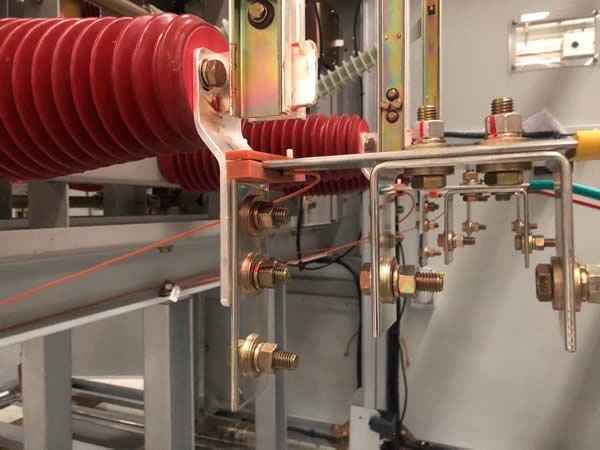
3. Switchgear Monitoring — What Is Being Monitored and Why

Switchgear — encompassing circuit breakers, disconnectors, busbars, and their enclosures — performs a fundamentally different function from a transformer. Its primary role is to reliably interrupt fault currents and isolate faulted sections of the network within milliseconds. If a circuit breaker fails to operate when called upon, the resulting protection failure can cascade into widespread equipment damage and system instability.
Core Failure Modes of Switchgear
Switchgear failure modes center on the mechanical and electrical integrity of the interrupting device. Key concerns include contact erosion and wear from repeated fault interruptions, operating mechanism degradation (springs losing tension, hydraulic systems leaking, linkages corroding), vacuum interrupter leakage in vacuum circuit breakers, SF₆ gas leakage in gas-insulated switchgear (GIS), insulation surface tracking and discharge caused by contamination or condensation, and busbar connection overheating due to joint oxidation or loosening.
The Goal of Switchgear Monitoring
Switchgear monitoring aims to confirm that the circuit breaker can operate reliably when the next fault occurs. This means tracking contact wear against manufacturer limits, verifying operating times remain within specification, detecting insulation degradation before flashover, and identifying overheating at busbar connections before thermal damage propagates.
4. Key Monitored Parameters — Side-by-Side Comparison
Transformer Monitoring Parameters
The parameters monitored on an oil-immersed transformer include dissolved gases in oil (hydrogen, methane, ethane, ethylene, acetylene, carbon monoxide, carbon dioxide), moisture content in oil, oil dielectric breakdown voltage, top oil temperature and winding hot-spot temperature, bushing capacitance and dissipation factor (tan δ), partial discharge activity, core grounding current, OLTC contact wear indicators, and cooling fan and pump status.
Switchgear Monitoring Parameters
The parameters monitored on switchgear include circuit breaker operating time (close and open), contact travel distance and velocity, trip and close coil current waveforms, cumulative fault interruption count and interrupted current magnitude, partial discharge activity (using TEV or UHF sensors), busbar and cable connection temperature, SF₆ gas density and dew point (for GIS), and spring charge motor current and timing.
Common Ground — and Where It Ends
Both equipment types benefit from partial discharge monitoring and temperature monitoring. However, the similarity is only conceptual. The sensor technology, installation method, signal processing algorithms, and acceptance criteria are entirely different for transformer applications versus switchgear applications.
5. Temperature Monitoring — Fluorescent Fiber Optic Sensing and Other Methods

Temperature is a universal indicator of equipment health. Excessive temperature accelerates insulation aging in transformers and indicates failing connections in switchgear. However, measuring temperature accurately inside high-voltage equipment presents significant challenges because of intense electromagnetic fields, high voltages, and limited physical access.
Why Conventional Thermocouples and RTDs Fall Short
Traditional temperature sensors such as thermocouples and resistance temperature detectors (RTDs) use metallic conductors that can act as antennas in strong electromagnetic fields, introducing measurement errors and, in worst cases, creating safety hazards. They are also vulnerable to ground potential rise during fault events. For these reasons, conventional sensors are unsuitable for direct placement on transformer windings or inside energized switchgear compartments.
Fluorescent Fiber Optic Temperature Sensors — The Preferred Solution
Fluorescent fiber optic temperature sensors have emerged as the industry-standard method for measuring temperatures in high-voltage environments. These sensors work on the principle of temperature-dependent fluorescence decay. A small phosphorescent probe is bonded to the measurement point — such as a transformer winding conductor or a switchgear busbar joint. A pulse of light is transmitted down the optical fiber to excite the phosphor. The rate at which the resulting fluorescence decays is precisely related to the temperature of the probe.
Key Advantages for Transformer Winding Hot-Spot Measurement
In oil-immersed transformer applications, fluorescent fiber optic temperature sensors are embedded directly into the winding during manufacturing. The sensors are placed at the locations predicted by thermal modeling to be the hottest points — typically in the top discs of the inner winding. Because the fiber is made entirely of glass and the probe contains no metallic components, the sensor is completely immune to electromagnetic interference, has no risk of creating a short circuit path, and withstands the full dielectric stress of the winding insulation system. The winding hot-spot temperature data obtained from fluorescent fiber optic sensors is far more accurate than the values estimated by the traditional thermal model method described in IEC 60076-7, which relies on top oil temperature and load current to calculate an approximate hot-spot value.
Application in Switchgear Temperature Monitoring
Inside switchgear compartments, fluorescent fiber optic temperature sensors are installed on busbar joints, cable terminations, and isolating contact interfaces — all locations where resistive heating from deteriorating connections poses a risk. The fully dielectric nature of the fiber optic cable eliminates the risk of tracking or flashover that a metallic sensor wire would introduce in the confined, high-field environment of a switchgear enclosure.
Fluorescent Fiber Optic vs. Infrared Thermal Imaging
Infrared (IR) thermal imaging through observation windows is another method used for switchgear temperature monitoring. While IR provides a thermal map of visible surfaces, it has several limitations compared to fluorescent fiber optic sensing. IR cameras require a direct line of sight to the target, cannot measure temperatures inside enclosed or shielded connections, are affected by emissivity variations on different surface materials, and typically provide only periodic snapshots rather than continuous monitoring. Fluorescent fiber optic sensors measure the actual conductor temperature continuously, around the clock, with accuracy typically within ±1°C — making them the superior choice for permanent online monitoring of critical connections.
Fluorescent Fiber Optic vs. Wireless Passive SAW Sensors
Surface acoustic wave (SAW) wireless temperature sensors are sometimes used in switchgear because they require no battery. However, SAW sensors rely on radio-frequency coupling that can be affected by the metallic enclosure of the switchgear, and their measurement update rate is typically slower than fiber optic systems. Fluorescent fiber optic temperature measurement systems provide faster response times, higher accuracy, and more reliable long-term performance in high-voltage switchgear environments.
Temperature Monitoring Data Interpretation
For transformers, winding hot-spot temperature data is used to calculate insulation aging rate according to IEC 60076-7 and IEEE C57.91 loading guides. When the hot-spot temperature exceeds the rated limit for extended periods, the cellulose insulation ages exponentially faster. For switchgear, temperature trends at connection points are compared against alarm and trip thresholds — a rising temperature trend at a busbar joint typically indicates increasing contact resistance due to oxidation, loosening, or contamination, requiring maintenance intervention before thermal failure occurs.
6. Sensors and Instrumentation — Two Different Worlds
Transformer Monitoring Sensors
The sensor suite for a comprehensive transformer online monitoring system includes online DGA sensors that continuously analyze dissolved gases in the insulating oil, oil moisture sensors using capacitive polymer technology, fluorescent fiber optic winding temperature sensors embedded in the winding, bushing tan δ monitoring devices that measure bushing capacitance and dissipation factor using voltage signals from bushing test taps, and UHF or acoustic partial discharge sensors mounted on the transformer tank.
Switchgear Monitoring Sensors
The sensor suite for switchgear condition monitoring includes coil current transducers that capture the trip and close coil current waveform of the circuit breaker, contact travel sensors (linear transducers or rotary encoders) that measure the mechanical motion of the breaker contacts, TEV (transient earth voltage) sensors or UHF couplers for partial discharge detection on the switchgear enclosure, fluorescent fiber optic temperature sensors on busbar connections, and SF₆ density and dew point transmitters for gas-insulated equipment.
No Cross-Compatibility
These two sensor suites share essentially no common components. A DGA sensor cannot monitor a circuit breaker. A breaker travel sensor has no application on a transformer. Even where both systems use partial discharge or temperature sensors, the specific sensor models, mounting methods, and signal processing requirements are different. Procurement, installation, commissioning, and maintenance must be planned separately for each.
7. Fault Types and Failure Modes Compared
Transformer Faults — Predominantly Gradual Insulation Degradation
Most oil-immersed transformer faults develop gradually over weeks, months, or years. Turn-to-turn insulation failure often begins as partial discharge activity that slowly erodes cellulose insulation until a conductive carbon track forms. Core multi-point grounding produces localized heating that generates dissolved gases detectable by DGA long before catastrophic damage occurs. Bushing deterioration manifests as a gradual increase in capacitance and dissipation factor. This slow degradation pattern makes online monitoring particularly effective for transformers because it provides a window of opportunity to detect and respond.
Switchgear Faults — A Mix of Gradual and Sudden
Switchgear faults include both gradual degradation and sudden mechanical failures. Contact erosion is gradual and predictable — each fault interruption removes a measurable amount of contact material. Insulation surface degradation from contamination and moisture is also gradual. However, operating mechanism failures — a broken spring, a seized latch, a corroded pivot pin — can occur suddenly with little prior warning. This mix of failure characteristics means that switchgear monitoring must track both slow trends and rapid state changes.
8. Data Analysis and Diagnostic Methods
Transformer Diagnostic Techniques
DGA interpretation is the cornerstone of transformer diagnostics. Engineers apply methods such as the Duval Triangle, Rogers Ratios, and the IEC three-ratio method to identify fault types from gas concentration patterns. Gas generation rates — the speed at which dissolved gas concentrations increase — indicate fault severity and urgency. Winding hot-spot temperature trends obtained from fluorescent fiber optic sensors are analyzed against loading profiles to calculate insulation loss-of-life. Partial discharge pattern recognition using phase-resolved PD (PRPD) diagrams helps distinguish between different discharge sources.
Switchgear Diagnostic Techniques
Switchgear diagnostics center on operating time analysis — comparing measured close and open times against manufacturer specifications and historical baselines. Deviations indicate mechanism wear or misadjustment. Coil current waveform analysis reveals the condition of the operating coil, the latch release timing, and the auxiliary contact sequence. Cumulative interrupted current tracking compares the total interrupted current (sum of all fault interruptions) against the contact wear curve to estimate remaining contact life. Temperature trending from fluorescent fiber optic sensors at busbar connections flags deteriorating joints before thermal runaway occurs.
9. Applicable Standards and Guidelines
Transformer Monitoring Standards
The key standards governing oil-immersed transformer monitoring and diagnostics include IEC 60076 (power transformer specifications), IEEE C57.12.00 (general requirements), IEC 60599 and IEEE C57.104 (DGA interpretation), IEC 60076-7 and IEEE C57.91 (loading guides and thermal modeling), and IEC 60270 (partial discharge measurement).
Switchgear Monitoring Standards
The key standards governing switchgear monitoring include IEC 62271-100 (high-voltage circuit breakers), IEC 62271-200 (metal-enclosed switchgear), IEC 62271-4 (condition monitoring guidelines for high-voltage switchgear), IEEE C37.10 (breaker condition monitoring guide), and IEC 60270 (partial discharge measurement — one of the few shared standards).
Minimal Overlap
Apart from IEC 60270 for partial discharge measurement, the two standards ecosystems are almost entirely independent. Engineers responsible for specifying monitoring systems must be familiar with both sets of standards and cannot assume that compliance with one implies applicability to the other.
10. Choosing the Right Monitoring Strategy for Your Substation
Transformer monitoring and switchgear monitoring are not competing investments — they are complementary programs that address different risk categories within the same substation. A transformer failure threatens asset replacement cost and long lead time. A breaker failure threatens protection reliability and system safety.
Prioritization Approach
For utilities building a monitoring program incrementally, a practical starting point is to deploy online DGA monitoring and fluorescent fiber optic winding temperature monitoring on the highest-value and oldest transformers first. Simultaneously, circuit breaker condition monitoring — particularly operating time and coil current analysis — should be deployed on breakers protecting those same critical transformers and on breakers with the highest fault interruption duty.
Unified Data Platform
While the sensors and analytics differ, the monitoring data from both equipment types should feed into a single asset performance management (APM) platform. This unified view allows asset managers to correlate transformer and switchgear health data, enabling holistic substation risk assessments rather than isolated equipment evaluations.
Frequently Asked Questions
Can the same monitoring system be used for both transformers and switchgear?
Generally no. The sensors, parameters, and diagnostic algorithms are fundamentally different for each equipment type. However, data from both monitoring systems can be integrated into a single asset management platform for unified analysis and reporting.
Which is more expensive to monitor — a transformer or switchgear?
A single transformer online monitoring system — particularly one including DGA and fluorescent fiber optic temperature sensors — typically costs more per unit than a single breaker monitoring system. However, a substation contains many more switchgear bays than transformers, so the total program investment can be comparable.
What is the most critical parameter for transformer monitoring?
Dissolved gas analysis (DGA) is widely regarded as the single most important transformer monitoring parameter because it can detect thermal faults, electrical discharges, and insulation degradation — all from a single measurement point in the oil.
What is the most critical parameter for switchgear monitoring?
Circuit breaker operating time (open and close) and contact wear are the most critical parameters. They directly indicate whether the breaker can reliably interrupt the next fault.
Why are fluorescent fiber optic sensors preferred for temperature monitoring?
Fluorescent fiber optic temperature sensors are entirely non-metallic and non-conductive, making them immune to electromagnetic interference, safe in high-voltage environments, and capable of measuring true conductor temperature at the exact point of interest — advantages that no metallic or wireless sensor can match.
Do both transformers and switchgear require partial discharge monitoring?
Yes, but with different approaches. Transformer PD monitoring typically uses UHF sensors mounted on the tank or acoustic sensors coupled to the tank wall. Switchgear PD monitoring typically uses TEV sensors on the enclosure surface or UHF couplers in the cable compartments.
How does SF₆ monitoring relate to switchgear but not transformers?
SF₆ is the insulating and arc-quenching medium in gas-insulated switchgear (GIS). Its density and moisture content directly determine interrupting capability and insulation integrity. Oil-immersed transformers use mineral oil or ester fluid — not SF₆ — as their insulation medium.
Can infrared cameras replace fiber optic sensors for switchgear monitoring?
Infrared cameras provide useful periodic thermal surveys but cannot replace fluorescent fiber optic sensors for continuous online monitoring. IR cameras require line-of-sight access, are affected by surface emissivity variations, and typically provide snapshots rather than continuous data streams.
How is transformer winding hot-spot temperature different from top oil temperature?
Top oil temperature is measured at the top of the transformer tank and represents the bulk oil temperature. Winding hot-spot temperature — measured directly by fluorescent fiber optic sensors embedded in the winding — is the actual peak temperature at the hottest point of the winding and is always higher than top oil temperature. It is the hot-spot temperature that determines insulation aging rate.
How do maintenance decisions differ between transformer and switchgear monitoring data?
Transformer monitoring data drives decisions such as scheduling oil processing, performing frequency response analysis, or reducing load to limit hot-spot temperature. Switchgear monitoring data drives decisions such as replacing vacuum interrupters or SF₆ cartridges, overhauling operating mechanisms, or re-torquing busbar connections identified as overheating.
Disclaimer: The information provided in this article is intended for general educational and informational purposes only. It does not constitute professional engineering advice. Always consult qualified engineers and adhere to applicable local codes and standards when specifying, installing, or maintaining monitoring systems for transformers and switchgear. www.fjinno.net assumes no liability for any actions taken based on the content of this article.

Fiber optic temperature sensor, Intelligent monitoring system, Distributed fiber optic manufacturer in China
 |
 |
 |