 INNO fibre optic temperature sensors ,temperature monitoring systems.
- Fluorescent fiber optic temperature sensors are the only reliable contact-based real-time temperature monitoring solution in MRI environments, featuring complete electromagnetic interference immunity
- Temperature range from -40°C to 260°C with ±1°C accuracy and response time <1 second; single unit monitors 1-64 measurement points simultaneously
- All-dielectric material construction ensures complete immunity to electromagnetic interference, preserving MRI image quality and ensuring patient safety
- Customizable parameters including probe diameter and fiber length (0-80 meters) suit medical, power utility, and industrial laboratory applications
- Contact-based single-point measurement: one fiber optic cable per hotspot, with flexible multi-channel configuration meeting complex monitoring requirements
Table of Contents
- 1. MRI Temperature Monitoring Requirements and Technical Challenges
- 2. Fluorescent Fiber Optic Temperature Sensor Operating Principle
- 3. Technical Specifications and Performance Comparison
- 4. Clinical Applications: MRI-Guided Thermal Therapy Monitoring
- 5. Power Equipment Temperature Monitoring Applications
- 6. Industrial and Laboratory Temperature Monitoring
- 7. Additional Medical Temperature Monitoring Applications
- 8. Temperature Data Acquisition and Visualization Systems
- 9. Customized Solution Advantages
- 10. Safety Standards and Quality Certifications
- Frequently Asked Questions (FAQ)
- Get Professional Temperature Monitoring Solutions
1. MRI Temperature Monitoring Requirements and Technical Challenges

Temperature monitoring in magnetic resonance imaging (MRI) environments presents unique challenges that conventional sensors cannot address. MRI scanners generate powerful magnetic fields ranging from 1.5T to 7T, along with intense radiofrequency (RF) pulses and rapidly switching gradient fields. These conditions render traditional metal-based temperature sensors completely unusable.
Clinical Temperature Monitoring Scenarios
Precise temperature control is critical in numerous MRI-guided therapeutic procedures. Tumor ablation therapies, including radiofrequency ablation (RFA) and microwave ablation, require real-time temperature feedback to ensure complete tumor destruction while protecting surrounding healthy tissue. Magnetic resonance-guided focused ultrasound (MRgFUS) treatments demand continuous temperature monitoring to achieve therapeutic temperatures of 55-60°C at the target site.
MRI Compatibility Requirements
Any temperature sensor deployed within the MRI bore must meet stringent compatibility criteria. The sensor must not contain ferromagnetic materials that could cause dangerous projectile effects or image artifacts. It must remain immune to electromagnetic interference from RF pulses and gradient switching. Most critically, the sensor itself must not compromise image quality or patient safety during thermal ablation procedures.
Temperature Control Standards
Clinical protocols for MRI thermal therapy typically specify temperature monitoring accuracy within ±1-2°C and response times under 2 seconds. Multi-point monitoring is often essential, requiring 4-16 simultaneous measurement locations to map thermal distributions accurately during procedures like laser interstitial thermal therapy (LITT).
2. Fluorescent Fiber Optic Temperature Sensor Operating Principle

Fluorescent fiber optic temperature sensors leverage the temperature-dependent properties of specialized phosphor materials to achieve highly accurate, MRI-compatible temperature measurement. Unlike traditional electrical sensors, these devices operate entirely on optical principles.
Temperature-Sensitive Fluorescence Mechanism
The sensor probe contains a micro-crystal of rare-earth-doped fluorescent material encapsulated at the fiber tip. When excited by blue or UV light transmitted through the optical fiber, this material emits fluorescence with intensity and decay time characteristics that vary predictably with temperature. By analyzing either the fluorescence intensity ratio at different wavelengths or the fluorescence lifetime, the system accurately determines temperature.
All-Dielectric Construction
The entire fiber optic temperature probe comprises only dielectric materials: silica glass fiber, fluorescent crystal, and polymer protective coating. This all-dielectric construction eliminates any metallic components, making the sensor completely transparent to magnetic fields and RF energy. The probe generates no eddy currents, produces no heating under RF excitation, and creates zero artifacts in MRI images.
Optical Signal Transmission
Excitation light from an LED or laser source travels through the fiber to the probe tip, stimulates fluorescence emission, and the return fluorescent signal travels back through the same fiber to a photodetector. The interrogation unit analyzes the fluorescence characteristics and converts them to temperature readings with ±1°C accuracy. This optical measurement approach provides inherent immunity to electromagnetic interference.
MRI Compatibility Foundation
The physical basis for MRI compatibility stems from the sensor’s non-conductive, non-magnetic nature. With no electrical currents to induce in the magnetic field and no ferromagnetic materials to interact with field gradients, fluorescent optical sensors operate flawlessly in environments where conventional thermocouples, thermistors, and RTDs fail completely.
3. Technical Specifications and Performance Comparison
Core Performance Parameters
| Technical Parameter | Specification | Customization Range |
|---|---|---|
| Temperature Range | -40°C to 260°C | Customizable per application |
| Measurement Accuracy | ±1°C | Standard configuration |
| Response Time | <1 second | Fast real-time monitoring |
| Fiber Length | 0-80 meters | Extendable on demand |
| Probe Diameter | Customizable | 0.5mm-5mm options |
| Measurement Channels | 1-64 channels | Multi-point monitoring per unit |
| Measurement Type | Contact single-point | One fiber per hotspot |
| EMI Immunity | Complete immunity | MRI/high-voltage suitable |
Fluorescent Fiber Optic vs. Traditional Temperature Sensing Technologies
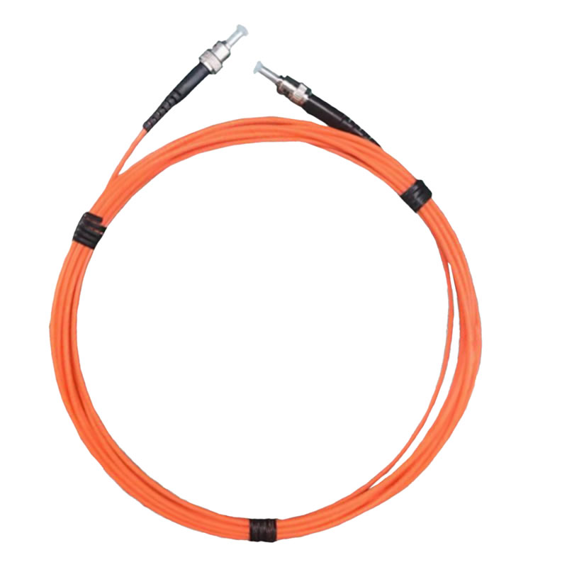
| Comparison Factor | Fluorescent Fiber Optic | Thermocouple | Thermistor | Infrared | PT100 RTD |
|---|---|---|---|---|---|
| MRI Compatibility | ✓ Fully compatible | ✗ Incompatible (metal) | ✗ Incompatible (EMI) | △ Limited (requires line-of-sight) | ✗ Incompatible (metal) |
| Temperature Range | -40°C to 260°C | -200°C to 1300°C | -50°C to 150°C | -20°C to 1000°C | -200°C to 850°C |
| Accuracy | ±1°C | ±0.5°C to 2°C | ±0.1°C to 1°C | ±2°C to 5°C | ±0.1°C to 0.5°C |
| Response Time | <1 second | 1-5 seconds | 2-10 seconds | Instant (non-contact) | 3-15 seconds |
| EMI Immunity | ✓ Complete immunity | ✗ Susceptible | ✗ Highly susceptible | ✓ Not affected | ✗ Susceptible |
| High Voltage Suitability | ✓ Insulated and safe | △ Requires special insulation | ✗ Not suitable | ✓ Non-contact safe | △ Requires special insulation |
| Multi-channel Expansion | ✓ 1-64 channels | △ Independent wiring needed | △ Independent wiring needed | ✗ Separate device per point | △ Independent wiring needed |
| Contact Measurement | ✓ Precise contact | ✓ Precise contact | ✓ Precise contact | ✗ Non-contact | ✓ Precise contact |
| Physical Size | Minimal (0.5-5mm) | Small (1-3mm) | Small (1-5mm) | Large (standalone device) | Medium (3-6mm) |
| Service Life | 5-10 years | 2-5 years | 3-7 years | 5-8 years | 5-10 years |
| Cost | Moderate | Low | Low | High | Moderate |
| Maintenance Requirements | Low | Medium | Medium | Low | Medium |
Key Advantages of Fluorescent Fiber Optic Sensors
- Only fully MRI-compatible solution: All-dielectric materials with zero metallic content
- Wide temperature coverage: -40°C to 260°C spans most applications
- Rapid response: <1 second real-time temperature change detection
- Electrical isolation and safety: Suitable for high-voltage power equipment monitoring
- Flexible multi-channel configuration: Up to 64 channels per single unit
- Long-distance transmission: 0-80 meter fiber length options
- Harsh environment resilience: Immune to electromagnetic, RF, and microwave interference
4. Clinical Applications: MRI-Guided Thermal Therapy Monitoring
Radiofrequency ablation (RFA) procedures for tumor treatment benefit enormously from fiber optic temperature monitoring. During RFA, temperature sensors positioned at multiple points around and within the tumor provide real-time feedback to control RF power delivery. This ensures complete tumor destruction at 60-100°C while preventing thermal damage to adjacent critical structures.
Magnetic Resonance-Guided Focused Ultrasound (MRgFUS)
MRgFUS treatments combine high-intensity focused ultrasound energy with MRI guidance to ablate tumors non-invasively. Fluorescent fiber optic probes can be placed percutaneously near the treatment zone to verify that target temperatures of 55-65°C are achieved and maintained for the prescribed duration. The 1-64 channel capability allows simultaneous monitoring at treatment margin, center, and critical adjacent anatomy.
Laser Interstitial Thermal Therapy (LITT)
LITT procedures for brain tumors insert laser fibers stereotactically to deliver thermal energy under real-time MRI thermometry. Supplementing MR thermometry with direct fiber optic temperature measurement at 4-8 points provides validation and enhanced safety monitoring. The sub-1-second response time captures rapid thermal changes during laser activation and cooling phases.
Cryoablation Temperature Distribution Measurement
While cryoablation freezes tissue to -40°C or below, accurate temperature monitoring at the ice ball margin is essential. Fluorescent sensors operating from -40°C enable precise monitoring of the freeze zone boundary, ensuring adequate tumor coverage while protecting adjacent structures from freezing injury.
Microwave Ablation Intraoperative Temperature Safety Monitoring
Microwave ablation generates intense electromagnetic fields that completely disable conventional electrical sensors. Fiber optic temperature monitoring systems remain immune to microwave interference, providing reliable multi-point temperature data throughout the procedure. The 260°C upper range accommodates the high temperatures achieved during microwave energy delivery.
Multi-Point Simultaneous Temperature Acquisition (1-64 Channels)
Complex ablation procedures may require monitoring 8-16 or more points simultaneously. A single fiber optic temperature measurement unit with 64-channel capacity can monitor extensive thermal distributions without cluttering the MRI suite with multiple devices. Each channel provides independent, contact-based temperature data from its dedicated fiber probe.
5. Power Equipment Temperature Monitoring Applications
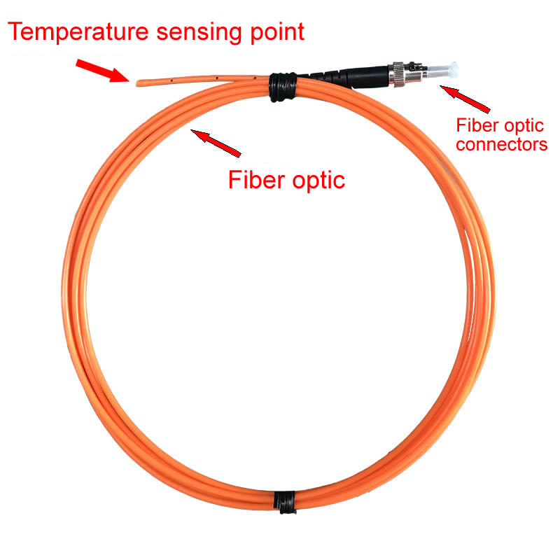
Transformer Winding Hotspot Online Monitoring
Power transformers develop localized hotspots in windings that can lead to insulation failure and catastrophic damage. Fiber optic temperature sensors installed at critical winding locations provide continuous hotspot monitoring without creating electrical safety hazards. The all-dielectric construction eliminates ground loop issues and maintains electrical isolation between high-voltage windings and monitoring systems.
High-Voltage Switchgear Contact Temperature Measurement
Deteriorating contacts in circuit breakers and disconnect switches generate excessive heat before failure. Fluorescent fiber optic probes attached directly to high-voltage contacts (up to hundreds of kilovolts) safely monitor temperature without introducing conductive paths. The 0-80 meter fiber length allows monitoring equipment to remain in safe, low-voltage areas.
Cable Joint Overheating Early Warning Systems
Underground cable joints are common failure points in power distribution networks. Installing fiber optic temperature monitoring at vulnerable joints enables early detection of developing hotspots before insulation breakdown occurs. Multi-channel systems monitor dozens of joints across substations from a central location.
Generator Stator Real-Time Temperature Tracking
Generator stator windings operate at elevated temperatures where overheating can cause rapid insulation degradation. Fiber optic sensors embedded in stator slots provide direct winding temperature measurement immune to the strong electromagnetic fields and high voltages present. Response times under 1 second enable protective relay systems to respond quickly to abnormal temperature rises.
Distribution Equipment Temperature Rise Monitoring Solutions
Switchboards, bus bars, and distribution panels benefit from permanent temperature monitoring installations that detect loose connections, overloading, and component failures. Up to 64 monitoring points per unit enable comprehensive coverage of large electrical installations while maintaining complete electrical isolation and safety.
6. Industrial and Laboratory Temperature Monitoring
Chemical Reactor Precise Temperature Control
Exothermic chemical reactions require precise temperature control to maintain product quality and prevent runaway conditions. Fiber optic temperature sensors immersed directly in reactive chemicals provide accurate measurement without introducing contamination or electrical hazards. The -40°C to 260°C range covers most chemical processing applications.
High-Temperature Furnace Multi-Point Temperature Distribution
Industrial furnaces, ovens, and kilns often exhibit significant temperature gradients that affect product quality. Installing 8-32 fiber optic probes throughout the heating chamber maps temperature distributions accurately. The sensors’ immunity to thermal radiation and electromagnetic fields from induction heating ensures reliable data in harsh environments.
Cryogenic Laboratory Environment Precision Monitoring
Low-temperature research down to -40°C benefits from fiber optic temperature measurement that doesn’t introduce heat conduction errors common with metallic sensors. The small probe diameter (0.5-1.5mm) minimizes thermal mass and provides fast response in cryogenic fluid environments.
Materials Heat Treatment Process Temperature Recording
Metallurgical heat treatment processes require documented temperature profiles for quality assurance and regulatory compliance. Fiber optic monitoring systems record multi-point temperature data with timestamps, creating permanent records of thermal cycles for each batch processed.
Research Equipment Multi-Channel Temperature Data Acquisition
Scientific research often demands simultaneous temperature measurement at numerous points with high accuracy and immunity to electromagnetic interference from experimental equipment. Fiber optic systems with 16-64 channels provide comprehensive temperature mapping for materials testing, thermal analysis, and experimental validation studies.
Hazardous Environment Safe Temperature Measurement
Explosive atmospheres in chemical plants, refineries, and pharmaceutical facilities prohibit electrical equipment that could generate ignition sparks. Fluorescent fiber optic sensors pose zero ignition risk, making them ideal for intrinsically safe temperature monitoring in Class I Division 1 hazardous locations. ATEX and IECEx certifications are available for regulated industries.
7. Additional Medical Temperature Monitoring Applications
Operating Room Equipment Temperature Safety Monitoring
Surgical instruments, electrosurgical units, and laser systems require temperature monitoring to prevent patient burns. Fiber optic sensors attached to instrument tips or tissue contact surfaces provide real-time temperature feedback, triggering alarms before thermal injury occurs.
Medical Refrigeration Continuous Temperature Recording
Pharmaceutical refrigerators and freezers storing vaccines, blood products, and medications must maintain strict temperature control with continuous documentation. Multi-channel fiber optic monitoring systems track temperatures across multiple storage units, creating audit trails for regulatory compliance.
Blood Product Storage Temperature Management
Blood banks require precise temperature control and alarming for red cells (1-6°C), platelets (20-24°C), and plasma (-18°C or below). Fiber optic temperature monitoring provides accurate, reliable measurement with alarm outputs integrated to facility management systems.
Sterilization Equipment Temperature Validation
Autoclaves and sterilizers must achieve validated temperatures throughout their chambers. Fiber optic probes positioned at multiple chamber locations verify temperature uniformity during validation cycles. The sensors’ ability to withstand 260°C accommodates high-temperature steam sterilization processes.
Extracorporeal Circulation System Temperature Monitoring
Heart-lung machines and dialysis equipment require precise temperature control of blood and fluid circuits. Fiber optic sensors in direct contact with blood provide accurate temperature feedback without thrombogenic metallic surfaces or electrical safety concerns.
Medical Device Temperature Performance Testing
Development testing of medical devices often involves temperature measurement under electromagnetic compatibility (EMC) testing conditions or within MRI scanners. Fluorescent fiber optic sensors enable accurate temperature data collection without interfering with EMC test fields or MRI operation.
8. Temperature Data Acquisition and Visualization Systems
Real-Time Temperature Curve Display and Recording
Fiber optic temperature measurement systems include software interfaces displaying real-time temperature trends for all active channels. Graphical displays show current readings, historical trends, and alarm status at a glance, enabling operators to identify developing issues quickly.
1-64 Channel Synchronized Temperature Data Collection
Multi-channel systems sample all inputs simultaneously, providing synchronized temperature snapshots across the monitored equipment or treatment area. Synchronous sampling is critical for analyzing thermal distributions and identifying hotspots relative to other measurement points.
Customizable Temperature Alarm Threshold Settings
Each channel supports independent high and low alarm thresholds with configurable alarm delays to prevent nuisance alarms. Alarm outputs include visual and audible indicators, relay contacts for equipment shutdown, and network notifications to facility management systems.
Historical Data Storage and Trend Analysis
Integrated data logging records all temperature measurements with timestamps to onboard memory or network storage. Analysis tools identify temperature patterns, calculate statistical summaries, and generate reports for quality documentation and regulatory compliance.
Integration with MRI Image Systems
Advanced MRI temperature monitoring systems overlay fiber optic temperature data onto MR images, creating fused displays that show both anatomical structures and measured temperatures. This integration provides clinicians with comprehensive situational awareness during thermal therapy procedures.
Multi-Point Temperature Distribution Visualization
Temperature mapping software converts multi-channel data into color-coded thermal distribution maps. These visualizations quickly reveal hotspots, cold zones, and temperature gradients across complex equipment or anatomical regions, supporting informed decision-making.
9. Customized Solution Advantages
Probe Diameter Customization
Fiber optic temperature probes are available in diameters from 0.5mm to 5mm to match application requirements. Minimally invasive procedures and tissue measurements utilize 0.5-1.5mm micro-probes that minimize trauma. Industrial applications benefit from robust 3-5mm probes with enhanced mechanical durability and chemical resistance.
Fiber Length Extension
Standard fiber lengths range from 1 to 80 meters, with custom lengths available beyond 80 meters for special installations. Longer fibers enable monitoring equipment placement in temperature-controlled equipment rooms while sensors operate in harsh environments like MRI bores, industrial furnaces, or outdoor substations.
Temperature Range Optimization
While the standard -40°C to 260°C range suits most applications, specialized sensors optimized for narrower ranges can provide enhanced accuracy or faster response. Cryogenic-optimized sensors for -40°C to 50°C or high-temperature versions for 100°C to 260°C are available upon request.
Flexible Multi-Channel Configuration
Systems scale from single-channel handheld units for spot checks to 64-channel rack-mounted installations for comprehensive monitoring. Channel count can be specified to exactly match the number of monitoring points required, optimizing both capability and cost.
Harsh Environment Adaptation
Probe construction can be customized with specialized protective sheaths for corrosive chemicals, high-pressure applications, or extreme mechanical stress. Stainless steel or PTFE jackets protect the fiber while maintaining electrical isolation and electromagnetic immunity.
Communication Protocol Customization
Fiber optic temperature systems support multiple output formats including analog 4-20mA, digital Modbus RTU/TCP, Ethernet TCP/IP, and custom protocols for integration with existing supervisory control and data acquisition (SCADA) systems or building management platforms.
10. Safety Standards and Quality Certifications
IEC 60601 Medical Device Electrical Safety
Medical-grade fiber optic temperature monitoring systems comply with IEC 60601-1 general safety requirements and IEC 60601-1-2 electromagnetic compatibility standards for medical electrical equipment. These certifications ensure patient and operator safety in clinical environments.
ASTM F2503 MRI Compatibility Testing
ASTM F2503 provides standardized test methods for evaluating medical device safety and compatibility in MRI environments. Fluorescent fiber optic sensors undergo testing for magnetic field interactions, RF heating, image artifacts, and device functionality within MRI bores to verify complete MRI compatibility.
FDA/CE/NMPA Medical Device Market Authorization
Products intended for clinical use in the United States require FDA 510(k) clearance or PMA approval. European markets require CE marking under the Medical Device Regulation (MDR). Chinese market access requires NMPA registration. These regulatory clearances demonstrate safety and efficacy for intended medical applications.
DL/T 984 Power Equipment Monitoring Standards
Electric utility applications reference industry standards such as DL/T 984 (China) or IEEE C57.91 (international) for transformer thermal monitoring. Fiber optic sensing systems designed for power applications meet these specifications for accuracy, reliability, and integration with utility monitoring infrastructure.
ATEX/IECEx Explosion Protection Certification
Hazardous location installations in chemical plants, refineries, and gas facilities require explosion-proof certifications. ATEX (Europe) and IECEx (international) certified fiber optic sensors are available for Zone 1/Division 1 explosive atmosphere monitoring, ensuring intrinsically safe operation.
ISO 13485 Quality Management System
Manufacturers of medical fiber optic temperature sensors maintain ISO 13485 quality management systems, ensuring consistent product quality, traceability, and regulatory compliance throughout design, manufacturing, and post-market surveillance processes.
Frequently Asked Questions (FAQ)
Q1: Why are fluorescent fiber optic sensors the only reliable solution for MRI temperature monitoring?
A: Fluorescent fiber optic temperature sensors use all-dielectric materials (silica glass and phosphor crystals) with zero metallic content. They are completely immune to 1.5T-7T magnetic fields and RF pulses, produce no MRI artifacts, experience no electromagnetic interference, and don’t compromise image quality. Traditional thermocouples, thermistors, and RTDs contain metal conductors that are completely incompatible with MRI environments.
Q2: How many temperature points can a single unit monitor simultaneously?
A: A single fiber optic temperature interrogator supports 1-64 channels, with each channel connecting to one fiber probe measuring one independent temperature point. This is contact-based single-point measurement, not distributed sensing, ensuring accurate, reliable data from each hotspot. Channel count can be customized based on your monitoring requirements.
Q3: What applications does the -40°C to 260°C temperature range cover?
A: The low end (-40°C) suits cryoablation, medical refrigeration, and cryogenic research. Mid-range temperatures cover MRI thermal therapy and surgical monitoring. The high end (260°C) accommodates RF ablation, microwave ablation, power equipment, and industrial furnaces. This range spans the vast majority of medical, power utility, and industrial temperature monitoring needs.
Q4: What advantages do fiber optic sensors have over infrared thermometry?
A: Infrared thermometry is non-contact and requires line-of-sight, making it susceptible to obstructions and surface emissivity variations with typical accuracy of ±2-5°C. It cannot measure internal temperatures. Fluorescent fiber optic sensors use contact-based measurement with probe direct contact to the measurement point, achieving ±1°C accuracy. They can measure internal tissue, equipment interiors, and other locations inaccessible to infrared, while remaining immune to electromagnetic interference.
Q5: How should I select fiber length from the 0-80 meter range?
A: MRI suite applications typically require 5-15 meters. Distributed power equipment monitoring may need 20-50 meters. Large industrial facilities or special spatial configurations can utilize 50-80 meters. Fiber length doesn’t affect measurement accuracy and can be freely selected based on the distance between equipment placement and monitoring points. Custom longer lengths are available.
Q6: How do I choose probe diameter from 0.5-5mm options?
A: Minimally invasive surgery and tissue measurements use 0.5-1.5mm small-diameter probes. Standard medical monitoring selects 1.5-3mm. Power equipment and industrial environments benefit from 3-5mm large-diameter probes for improved mechanical strength. All diameters are customizable to match insertion space requirements and durability needs.
Q7: Why is <1 second response time important?
A: During RF ablation and microwave ablation, temperature can rise tens of degrees per second. Sub-second response time captures rapid temperature changes, triggering protective alarms before thermal damage occurs. Power equipment failures also cause rapid temperature rise, making fast response critical for early warning and prevention.
Q8: Can fluorescent fiber optics be used in high-voltage power environments?
A: Absolutely. Fiber optic cables are insulating dielectrics immune to high voltage electric fields, with no risk of leakage or short circuits. This represents a major safety advantage over thermocouples, RTDs, and other metallic sensors. They’re particularly suited for transformer, switchgear, and other high-voltage equipment temperature monitoring.
Q9: How does cost compare to thermocouples?
A: Per-point probe cost for fluorescent fiber optics is moderately higher than thermocouples, but considering: ① No additional EMI shielding required ② Single unit supports 64 channels ③ 5-10 year service life (vs. 2-5 years for thermocouples) ④ Minimal maintenance and replacement, overall lifecycle cost favors fiber optics, especially for multi-point monitoring applications.
Q10: Does ±1°C accuracy meet medical and industrial requirements?
A: For thermal therapy (target 40-45°C), ablation (target 60-100°C), power equipment alarms (typically 80-120°C), and industrial process control, ±1°C accuracy fully satisfies safety and control requirements. For applications requiring higher precision (such as ±0.5°C), please consult regarding custom solutions.
Q11: Can fluorescent fiber optics be used in explosive hazardous environments?
A: Yes. Fiber optic sensors pose no electrical spark risk and are intrinsically safe, suitable for chemical, petroleum, and mining explosive gas environments. ATEX and IECEx explosion-proof certified products are available, ensuring safe temperature monitoring in hazardous areas.
Q12: How are multi-channel systems wired and managed?
A: Each channel uses one independent fiber, with all fibers converging to a single temperature interrogator. Fibers are flexible with small diameter (typically 3-5mm jacket), enabling flexible routing through conduits or cable trays for centralized installation. Software interfaces allow independent labeling, threshold setting, and data viewing for all 64 channels, providing convenient management.
Q13: What other strong electromagnetic interference environments are suitable besides MRI?
A: Induction heating equipment, microwave systems, RF generators, electromagnetic shielded room testing, radar systems, particle accelerators, plasma equipment, and all strong EMI environments. Traditional electrical sensors experience data corruption or damage in these environments, while fluorescent fiber optic sensors remain completely unaffected.
Q14: How is long-term measurement stability ensured?
A: Fluorescent materials undergo special encapsulation processes for photo-drift resistance and anti-aging. Products undergo thermal cycling and long-term stability testing before shipment. Annual calibration verification is recommended (standard calibration service provided) to ensure accuracy stability throughout the 5-10 year service life.
Q15: Does the system support remote monitoring and data export?
A: Yes. Data acquisition software supports remote monitoring via Ethernet, RS485, and other interfaces. Data can be exported in Excel, CSV, and other formats, with support for integration with SCADA, HIS, and other supervisory systems, meeting medical record-keeping and industrial automation requirements.
Get Professional Temperature Monitoring Solutions
Contact us today to receive:
- Detailed technical documentation and product specifications
- Customized solutions tailored to your specific application
- Accurate product quotations and delivery timelines
Contact our team for consultation

Fiber optic temperature sensor, Intelligent monitoring system, Distributed fiber optic manufacturer in China
 |
 |
 |