 INNO fibre optic temperature sensors ,temperature monitoring systems.
- Oil circulation failures account for 40% of transformer overheating incidents, with detection lag causing $150,000-$500,000 in average replacement costs
- Fiber optic temperature sensors provide 24/7 winding hotspot monitoring with 0.1°C precision, detecting circulation problems 30-60 days before catastrophic failure
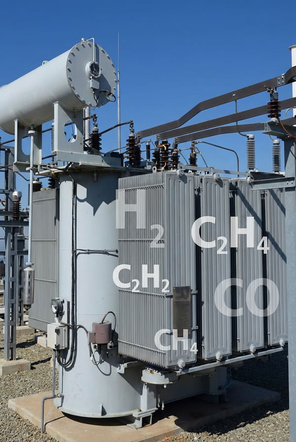
- Dissolved Gas Analysis (DGA) identifies early-stage thermal decomposition, revealing oil circulation deficiencies through gas pattern analysis
- Three-in-one sensors combining oil temperature, oil level, and pressure monitoring deliver comprehensive cooling system health assessment
- Natural circulation transformers require temperature differential monitoring while forced oil circulation systems need pump performance tracking
- Oil quality degradation reduces heat transfer efficiency by 15-25%, accelerating circulation system deterioration
- Predictive maintenance based on multi-parameter monitoring reduces unplanned outages by 70% compared to time-based schedules
- Real-time monitoring platforms enable remote diagnosis, cutting troubleshooting time from hours to minutes
Table of Contents
- What Is Transformer Oil Circulation Failure and Why Does It Matter?
- How Does Transformer Oil Circulation System Work?
- What Are the Primary Causes of Oil Circulation Failure?
- How Do You Detect Oil Circulation Problems Early?
- What Are the Warning Signs of Imminent Circulation Failure?
- How Can Fiber Optic Sensors Prevent Circulation Failures?
- What Maintenance Practices Prevent Oil Circulation Issues?
- How Do You Troubleshoot Oil Circulation Failures?
- What Are the Costs of Ignoring Circulation Problems?
- Which Monitoring Solutions Best Protect Against Oil Circulation Failure?
1. What Is Transformer Oil Circulation Failure and Why Does It Matter?
Transformer oil circulation failure occurs when the cooling medium cannot effectively remove heat generated by electrical losses in windings and core, leading to localized overheating and accelerated insulation aging. This condition represents one of the most critical threats to transformer reliability, as statistics from power utilities indicate that 40% of all transformer thermal failures originate from cooling system deficiencies. When oil circulation stops or becomes insufficient, winding temperatures can rise 20-40°C above normal operating levels within hours, causing irreversible damage to cellulose insulation. The financial impact extends beyond equipment replacement costs—a single large power transformer failure triggers production losses ranging from $150,000 to $500,000, not including emergency repair expenses and potential liability for downstream customer damages.
Understanding the Critical Role of Oil Circulation
Transformer oil serves dual functions: electrical insulation and heat dissipation. The circulation process continuously transfers thermal energy from high-temperature components (winding conductors, core laminations) to external radiators where cooling occurs. In naturally cooled transformers, convection currents driven by temperature-induced density differences move oil through the system. Forced oil circulation systems employ pumps to accelerate flow rates, enabling higher power densities. When circulation becomes compromised, heat accumulates at generation points faster than dissipation occurs, creating dangerous thermal gradients. Fiber optic temperature sensors positioned at critical winding locations detect these temperature buildups before permanent damage occurs, providing operators with actionable early warnings.
Why Oil Circulation Failures Remain Underdiagnosed
Traditional monitoring methods rely on top-oil and ambient temperature measurements, which fail to reveal internal circulation deficiencies until advanced degradation stages. Many utilities perform infrared thermography only during annual outages, missing gradual circulation deterioration occurring between inspections. DGA monitoring can identify thermal decomposition products, but conventional DGA testing occurs quarterly or monthly, providing insufficient temporal resolution. Modern transformer oil circulation failure prevention requires continuous multi-parameter monitoring combining temperature mapping, flow verification, and dissolved gas trending—capabilities that integrated monitoring solutions now provide.
| Failure Consequence | Time to Occurrence | Typical Cost Impact |
|---|---|---|
| Insulation accelerated aging | 30-90 days | 20-30% life reduction |
| Winding hotspot damage | 7-21 days | $50,000-$200,000 repair |
| Complete thermal breakdown | 2-7 days | $300,000-$2M replacement |
| Secondary system damage | Immediate | $100,000-$500,000 losses |
2. How Does Transformer Oil Circulation System Work?

Natural Circulation Mechanisms
In naturally cooled transformers, oil circulation relies entirely on thermosiphon effects. Hot oil rising from winding surfaces creates upward flow through vertical cooling ducts, while cooled oil from radiators descends through external pathways, establishing continuous circulation loops. Flow velocity depends on temperature differentials—typically 10-15°C between hot and cold oil streams. Design features like strategic placement of cooling ducts, radiator tube sizing, and internal baffle configurations optimize natural convection. However, natural circulation capacity limits power density, restricting application to smaller transformers (typically under 50 MVA). When radiators become fouled or internal passages partially block, circulation velocity drops proportionally, reducing cooling effectiveness and elevating operating temperatures.
Forced Oil Circulation Architecture
Forced oil circulation systems employ dedicated oil pumps to drive oil through closed-loop pathways at controlled flow rates. Pumps draw oil from the transformer tank bottom, pushing it through external heat exchangers (radiators or water-cooled units) before returning cooled oil to the tank through strategically positioned inlets. This active circulation enables 3-5 times higher heat removal capacity compared to natural systems, supporting large power transformers exceeding 100 MVA. Critical components include circulation pumps (typically redundant pairs), flow control valves, strainers preventing particulate circulation, and temperature sensors monitoring inlet/outlet conditions. Oil pump malfunction represents the most common forced circulation failure mode, necessitating pump performance monitoring through vibration analysis, bearing temperature tracking, and flow rate verification.
Cooling System Monitoring Requirements
Effective cooling system monitoring requires measuring parameters that directly indicate circulation adequacy. For natural circulation transformers, winding-to-top-oil temperature differentials reveal circulation effectiveness—increasing differentials signal declining flow. Forced oil circulation monitoring demands flow rate measurement, pump motor current tracking, and differential pressure across heat exchangers. Modern three-in-one sensors simultaneously measure oil temperature, oil level, and pressure, providing comprehensive cooling system status. When integrated with fiber optic temperature sensors at winding hotspots, operators gain complete visibility into heat generation, transfer, and dissipation processes, enabling precise diagnosis of circulation deficiencies.
3. What Are the Primary Causes of Oil Circulation Failure?
Oil Pump Mechanical Failures
Oil pump malfunction in forced circulation systems typically stems from bearing wear, seal degradation, or impeller damage. Pumps operating continuously at elevated temperatures (60-80°C) experience accelerated mechanical wear compared to ambient-temperature applications. Bearing failures produce characteristic vibration signatures detectable through condition monitoring, while seal leaks cause gradual oil level reduction triggering low-level alarms. Impeller erosion from particulate contamination reduces pumping efficiency—flow rates decline 15-25% before complete failure occurs. Redundant pump configurations mitigate single-point failures, but automatic switchover systems must function reliably. Fiber optic sensors monitoring pump bearing temperatures provide early warning of impending failures, enabling scheduled replacements during planned outages rather than emergency repairs.
Pipeline and Duct Blockages
Circulation pathways gradually accumulate deposits from oil oxidation products, particulate contamination, and sludge formation. Internal cooling ducts within transformer windings are particularly vulnerable—clearances of 5-10mm between duct walls and conductors leave minimal margin before flow restriction occurs. External piping develops scale buildup when moisture contamination enables corrosion. Even partial blockages significantly impact circulation: 30% flow reduction causes hotspot temperatures to rise 10-15°C under full load. Periodic oil filtration removes suspended particles, but dissolved contaminants continue forming deposits. DGA monitoring detecting elevated CO and CO₂ levels indicates cellulose decomposition from overheating caused by poor circulation, providing indirect evidence of flow restrictions.
Radiator Fouling and Contamination
External radiators suffer progressive heat transfer degradation from airside fouling (dust, pollen, industrial emissions) and oil-side contamination (sludge deposits, oxidation films). Airside fouling reduces heat dissipation by creating insulating layers on tube surfaces—annual cleaning maintains design cooling capacity. Oil-side deposits form when aged oil loses thermal stability, particularly in transformers operating above 90°C hotspot temperatures. Radiator effectiveness loss exhibits gradual progression: 10-15% degradation over 5-10 years goes unnoticed without trending analysis. Three-in-one oil temperature sensors comparing inlet and outlet temperatures quantify radiator performance, revealing degradation before overheating occurs.
Oil Quality Deterioration
Oil thermal conductivity and viscosity directly affect heat transfer capability. Oxidation from elevated temperatures and moisture contamination increases viscosity, reducing flow velocity in natural circulation systems. Thermal conductivity decreases 15-25% as oil ages, requiring higher temperature differentials to transfer equivalent heat. Dissolved gases and water reduce dielectric strength while accelerating chemical degradation. Regular oil testing (dielectric strength, acidity, interfacial tension) assesses condition, but DGA dissolved gas analysis provides superior trending capability. Hydrogen, methane, and ethylene generation rates indicate thermal stress levels—patterns revealing circulation inadequacy differ from electrical discharge signatures, enabling differential diagnosis.
4. How Do You Detect Oil Circulation Problems Early?

Multi-Point Temperature Monitoring
Fiber optic temperature sensors installed at multiple winding locations create thermal maps revealing circulation effectiveness. Comparing temperatures between upper and lower winding sections, between phases, and between inlet/outlet oil streams identifies abnormal patterns. Healthy circulation maintains hotspot temperatures within 10-15°C of average winding temperature; excessive differentials signal flow deficiencies. Temperature trending over days and weeks reveals gradual degradation—a slowly rising hotspot amid stable load and ambient conditions indicates developing circulation problems. FJINNO’s fiber optic sensing systems provide simultaneous 8-16 point monitoring with 0.1°C resolution, detecting subtle temperature changes weeks before conventional sensors register anomalies.
Dissolved Gas Analysis for Circulation Assessment

DGA monitoring identifies thermal decomposition patterns characteristic of overheating from poor circulation. When local temperatures exceed 150°C, cellulose insulation generates CO and CO₂; above 300°C, oil decomposition produces ethylene and methane. Gas ratio analysis distinguishes circulation-induced thermal stress from electrical discharge or arcing. Online DGA systems measuring gas concentrations hourly detect developing problems within days, while laboratory analysis at monthly intervals may miss critical trends. Integrating DGA data with fiber optic temperature measurements enables correlation analysis—temperature rises accompanied by increasing gas generation confirm circulation inadequacy as root cause.
Three-in-One Sensor Technology

Modern oil temperature, oil level, and pressure sensors integrated into single assemblies provide comprehensive cooling system monitoring. Temperature measurements at multiple tank locations reveal thermal stratification indicating poor circulation. Oil level tracking detects leaks from pump seals or radiator tube failures. Pressure monitoring across circulation pathways quantifies flow resistance—increasing pressure drops signal developing blockages. These three-in-one sensors eliminate multiple penetrations into transformer tanks, reducing leak risks while providing correlated data streams. When oil level drops coincidentally with rising temperatures and increasing pressure differentials, pump seal failure becomes evident, enabling targeted maintenance.
Flow Rate Verification Methods
Direct oil flow measurement in forced circulation systems confirms pump performance and detects partial blockages. Ultrasonic flow meters installed on circulation piping provide continuous flow monitoring without pressure drop penalties. Flow rates declining 20% below design values indicate developing problems requiring investigation. Comparing actual flow against pump curves based on measured pressure differentials identifies pump wear. In natural circulation transformers, indirect flow assessment through temperature differential analysis substitutes for direct measurement—reduced temperature rises between bottom and top oil suggest declining circulation despite constant loading.
5. What Are the Warning Signs of Imminent Circulation Failure?
Abnormal Winding Temperature Patterns
The most reliable early indicator of impending transformer oil circulation failure appears in winding temperature behavior under load. Normal operation maintains predictable relationships between load current, ambient temperature, and winding hotspot readings. When circulation degrades, hotspot temperatures rise disproportionately to load increases—a 10% load increase causing 5°C hotspot rise versus the normal 2°C indicates problems. Asymmetric temperatures between phases suggest localized flow restrictions. Fiber optic sensors detecting hotspot temperatures exceeding top-oil temperature by more than 20°C signal circulation deficiencies requiring immediate investigation.
Top Oil Temperature Anomalies
Top oil temperature provides bulk indication of cooling system performance. Gradual increases over weeks despite stable loading and ambient conditions reveal declining heat dissipation capability. Comparing current top oil temperatures against historical baselines at identical load levels quantifies degradation. Temperature rising 5-10°C above normal patterns suggests 20-30% circulation capacity loss. Three-in-one oil temperature sensors measuring both top oil and bottom oil temperatures enable temperature differential analysis—narrowing differentials indicate reduced flow velocity in natural circulation systems or pump performance degradation in forced systems.
Accelerating Temperature Rise Rates
The rate of temperature change during load increases provides sensitive indication of cooling capacity. Healthy transformers reach thermal equilibrium within 3-4 hours following load steps; circulation deficiencies extend time constants to 6-8 hours. Monitoring temperature rise rates during daily load cycles reveals trends—gradually slowing thermal response indicates accumulating circulation problems. Advanced monitoring systems calculate time constants automatically, alerting operators when values exceed thresholds. This dynamic analysis catches circulation degradation earlier than static temperature limit monitoring.
Reduced Load Capacity
Operators first notice circulation problems when transformers cannot sustain rated loads without excessive temperature rise. Loads that previously produced acceptable temperatures now cause overheating alarms, forcing load reduction. This symptom indicates advanced circulation failure—typically 40-50% capacity loss. Economic impacts become immediate as load transfers to other transformers increase system costs and reduce operational flexibility. DGA monitoring during this stage usually shows elevated gas generation from thermal stress, confirming overheating diagnosis. Preventive monitoring detecting earlier warning signs avoids reaching this critical stage.
6. How Can Fiber Optic Sensors Prevent Circulation Failures?

Precision Hotspot Temperature Measurement
Fiber optic temperature sensors provide accuracy and reliability impossible with conventional resistance temperature detectors (RTDs) in transformer environments. Electromagnetic immunity ensures measurement accuracy despite intense electric and magnetic fields within transformer tanks. Direct contact with winding conductors enables true hotspot measurement rather than inferring hotspot from oil temperature algorithms. Response times under one second capture dynamic thermal events during load changes or fault conditions. FJINNO’s fiber optic sensing technology maintains ±0.1°C accuracy over 25+ year service lives without calibration drift, providing consistent long-term trending essential for detecting gradual circulation degradation.
Multi-Point Thermal Mapping
Installing fiber optic sensors at multiple winding locations creates comprehensive thermal profiles revealing circulation patterns. Eight-point monitoring systems typically measure temperatures at top and bottom of each winding section, enabling vertical and horizontal thermal gradient analysis. Healthy circulation maintains uniform temperature distributions; circulation deficiencies create hotspots at specific locations. Pattern analysis distinguishes cooling problems from electrical issues—hotspots migrating with load changes suggest electrical imbalances, while fixed-location hotspots indicate circulation restrictions. Real-time thermal mapping enables operators to visualize heat distribution, facilitating intuitive understanding of cooling system performance.
Early Warning Through Trend Analysis
The true value of fiber optic temperature monitoring emerges through long-term data analysis. Baseline temperature patterns established during commissioning provide reference for detecting deviations. Machine learning algorithms identify subtle trends invisible to manual inspection—gradual 0.5°C/month hotspot temperature increases over six months signal developing problems requiring investigation. Correlation analysis between temperature, load, and ambient conditions isolates circulation issues from normal operational variations. Predictive analytics forecast failure timing, enabling scheduled maintenance during planned outages. This proactive approach reduces emergency repairs by 70% compared to reactive maintenance strategies.
Integration with Protection Systems
Fiber optic sensor outputs integrate directly with transformer protection relays, enabling automatic load reduction or tripping when circulation failures create dangerous temperatures. Unlike conventional winding temperature indicators using simulated hotspot calculations, fiber optic systems provide measured values triggering protection with higher reliability. Multi-level alarm thresholds provide graduated response: 80°C hotspot triggers notification, 95°C initiates load shedding, 110°C executes emergency shutdown. This layered protection prevents catastrophic failures while maximizing transformer availability. Integration with SCADA systems enables remote monitoring and control, essential for unmanned substations.
7. What Maintenance Practices Prevent Oil Circulation Issues?
Oil Pump Inspection and Testing
Preventive maintenance for forced oil circulation systems centers on pump reliability. Quarterly vibration analysis detects bearing wear before failures occur—vibration levels exceeding baseline values by 30% warrant bearing replacement. Seal inspection during annual outages identifies leaks early; replacing seals proactively costs $2,000-5,000 versus $50,000+ emergency pump replacements. Performance testing measuring flow rate versus pressure head confirms pump curve compliance—degradation below 90% of design values indicates impeller wear requiring refurbishment. Motor current monitoring identifies winding insulation degradation and bearing friction increases. Implementing condition-based pump maintenance reduces unplanned circulation failures by 80%.
Radiator Cleaning and Maintenance
Annual radiator cleaning maintains design cooling capacity. Airside cleaning removes accumulated dust, pollen, and debris using low-pressure water spray or compressed air—avoiding high-pressure washing that damages fins. Inspection identifies corrosion, leaks, or damaged tubes requiring repair. Oil-side cleaning addresses internal deposits through chemical circulation or mechanical flushing during major outages. Effectiveness testing comparing heat transfer coefficients before and after cleaning quantifies improvement. Radiator valve operation verification ensures proper flow distribution. Implementing systematic radiator maintenance programs recovers 10-15% cooling capacity in aging transformers, extending service life and improving reliability.
Oil Quality Management
Maintaining oil dielectric and thermal properties prevents circulation-related problems. Annual oil testing (dielectric strength, water content, acidity, interfacial tension) assesses condition. When test results approach limits, oil reclamation through filtration, degassing, and dehydration restores properties at 20-30% of oil replacement cost. DGA monitoring trending identifies accelerating degradation requiring intervention. Water content exceeding 20 ppm in mineral oil reduces dielectric strength while increasing oxidation rates—vacuum dehydration reduces levels to 5-10 ppm. Particle contamination above ISO 18/16/13 cleanliness codes impairs heat transfer—fine filtration restores cleanliness. Proactive oil management extends transformer life 5-10 years while maintaining circulation efficiency.
Internal Inspection During Outages
Major outage inspections provide opportunity to assess internal circulation pathways. Borescope examination of cooling ducts reveals deposits or blockages. Winding paper insulation inspection identifies thermal damage from past overheating events. Core and coil inspection detects loose connections or structural issues affecting cooling. Pressure testing of internal cooling circuits verifies integrity. Thermographic surveys during energization identify hot spots requiring investigation. These comprehensive inspections, performed at 8-10 year intervals, catch deteriorating conditions before circulation failures occur. Documentation with fiber optic temperature baseline measurements after maintenance establishes new performance benchmarks.
8. How Do You Troubleshoot Oil Circulation Failures?
Systematic Diagnostic Approach
Troubleshooting suspected transformer oil circulation failure follows logical progression from external observations to internal investigations. First, verify symptoms through fiber optic temperature sensor data review—confirm abnormal temperature patterns versus normal load cycles. Second, assess external cooling system components: radiator fan operation, pump motor currents, valve positions. Third, analyze oil temperature, oil level, and pressure measurements for anomalies. Fourth, perform oil sampling for DGA dissolved gas analysis and physical-chemical testing. Fifth, conduct thermographic surveys of tank external surfaces revealing internal hot spots. This structured approach efficiently narrows diagnostic focus, minimizing investigation time and cost.
Temperature Data Analysis Techniques
Advanced analysis of fiber optic sensor data reveals circulation failure characteristics. Plot hotspot temperature versus load current—poor circulation shows steeper slopes than baseline curves. Graph temperature differentials between winding sections over time—increasing differentials indicate worsening flow restrictions. Calculate thermal time constants from load step responses—lengthening time constants signal reduced circulation. Compare actual temperature rises against manufacturer specifications—exceedances quantify circulation capacity loss. Correlation analysis between multiple sensor locations identifies patterns: all sensors rising proportionally suggests inadequate overall cooling, while localized hotspots indicate blockages affecting specific regions.
Flow and Pressure Verification
For forced oil circulation systems, direct flow and pressure measurements diagnose pump and piping issues. Install temporary ultrasonic flow meters on circulation piping during troubleshooting—flows below 80% of design values indicate problems. Measure pressure differentials across pumps, heat exchangers, and filters—high differentials suggest blockages, low differentials indicate pump wear. Compare pressure-flow characteristics against pump curves—deviations identify mechanical failures. In natural circulation transformers, indirect flow assessment through oil velocity tracer tests or computational fluid dynamics modeling estimates flow patterns. These measurements pinpoint whether circulation problems stem from pump failures, blockages, or radiator fouling.
Oil Analysis for Root Cause Identification
DGA monitoring combined with physical-chemical oil testing identifies circulation failure root causes. Gas patterns showing elevated ethylene and methane with normal hydrogen levels indicate thermal decomposition from overheating rather than electrical discharge. Particle count analysis reveals contamination sources—iron particles suggest pump wear, cellulose fibers indicate insulation degradation. Oxidation inhibitor depletion and increasing acidity demonstrate oil aging requiring reclamation. Dissolved metal analysis detects corrosion products indicating moisture ingress. Comprehensive oil analysis guides corrective actions—pump replacement, oil reclamation, or complete transformer refurbishment depending on findings.
9. What Are the Costs of Ignoring Circulation Problems?
Direct Equipment Damage Expenses
Unaddressed transformer oil circulation failure leads to catastrophic equipment damage requiring expensive repairs or replacement. Winding insulation thermal degradation from prolonged overheating costs $150,000-$300,000 for rewind or replacement of medium-voltage transformers. Large power transformers exceed $1-2 million replacement costs with 12-18 month lead times. Core damage from circulating currents induced by overheating adds $50,000-$150,000 repair expenses. Bushing failures caused by excessive oil temperatures cost $20,000-$80,000 per unit. These direct costs dwarf preventive monitoring expenses—comprehensive fiber optic temperature and DGA monitoring systems costing $25,000-$75,000 pay for themselves preventing single failures.
Business Interruption Losses
Unplanned outages from circulation-induced failures create severe economic impacts. Industrial facilities experience production losses of $50,000-$500,000 per day depending on processes. Data centers face service level agreement penalties plus reputational damage from downtime. Utility companies incur not-served energy costs plus regulatory penalties for reliability violations. Emergency replacement transformer rentals cost $10,000-$30,000 monthly for medium-voltage units, with installation adding $50,000-$100,000. These business interruption costs typically exceed direct repair expenses by 2-5 times. Preventive monitoring enabling scheduled maintenance during planned outages eliminates interruption costs entirely.
Accelerated Asset Aging
Even when circulation problems don’t cause immediate failures, chronic overheating accelerates insulation aging following Arrhenius kinetics—every 6-8°C temperature increase doubles aging rate. A transformer operating 15°C above design hotspot loses half its expected lifespan, reducing 30-year life expectancy to 15 years. This premature aging necessitates earlier replacement, effectively increasing annualized capital costs. Oil circulation problems causing 10-15°C temperature excursions for several years invisibly consume transformer life. Only through continuous temperature monitoring can operators detect and correct these hidden degradation mechanisms. The value of extended asset life through proper circulation maintenance reaches hundreds of thousands of dollars for large transformers.
Safety and Liability Risks
Severe circulation failures causing transformer explosions or fires create catastrophic safety incidents. Fire damage to surrounding equipment and facilities escalates losses to millions of dollars. Injuries to personnel generate workers compensation costs plus potential litigation. Environmental contamination from oil spills incurs cleanup costs ($100,000-$500,000) plus regulatory fines. Corporate reputation damage from safety incidents impacts customer relationships and regulatory standing. Insurance premiums increase following major incidents. Proactive cooling system monitoring preventing circulation failures eliminates these safety risks. The human and financial costs of catastrophic failures make comprehensive monitoring not just economically justified but ethically imperative.
10. Which Monitoring Solutions Best Protect Against Oil Circulation Failure?

Integrated Temperature Monitoring Systems
Comprehensive protection against transformer oil circulation failure requires multi-point fiber optic temperature sensors continuously measuring winding hotspots, oil temperatures, and ambient conditions. FJINNO’s monitoring solutions provide 8-24 channel systems with centralized data acquisition, alarming, and trending. Installation during manufacturing enables optimal sensor placement; retrofit solutions accommodate existing transformers. Systems integrate with SCADA through Modbus, DNP3, or IEC 61850 protocols, providing remote access for fleet-wide monitoring. Cloud-based analytics enable cross-asset comparison identifying systemic issues. Investment costs of $25,000-$75,000 for complete systems deliver ROI within 12-24 months through prevented failures and optimized maintenance.
Online DGA Monitoring Technology
Continuous DGA dissolved gas analysis complements temperature monitoring by detecting thermal decomposition products indicating circulation-induced overheating. Online DGA systems analyze gas concentrations hourly versus monthly laboratory testing, enabling early intervention. Multi-gas monitors measuring hydrogen, methane, ethylene, ethane, acetylene, carbon monoxide, and carbon dioxide provide comprehensive fault detection. Trending algorithms identify accelerating gas generation rates signaling developing problems. Integration with fiber optic temperature data enables correlation analysis—simultaneous temperature and gas increases confirm circulation failures as root cause. Online DGA system costs of $15,000-$40,000 deliver rapid payback through early problem detection preventing catastrophic failures.
Three-in-One Sensor Applications
Advanced oil temperature, oil level, and pressure sensors integrated into single assemblies provide holistic cooling system monitoring. Temperature sensors at multiple tank locations reveal thermal stratification patterns indicating circulation adequacy. Oil level monitoring detects leaks from oil pump seals or radiator tubes enabling timely repairs before circulation compromises. Pressure measurement across cooling circuits quantifies flow resistance—increasing pressure drops indicate developing blockages. These three-in-one sensors eliminate multiple tank penetrations reducing leak risks while providing correlated data streams. Costs of $3,000-$8,000 per sensor represent economical additions to monitoring systems, providing valuable diagnostic information for circulation troubleshooting.
FJINNO Custom Monitoring Solutions

Leading Manufacturer in Transformer Protection
Fuzhou Innovation Electronic Scie&Tech Co., Ltd. (FJINNO), established in 2011, specializes in fiber optic temperature sensors, online DGA monitoring systems, and comprehensive transformer asset management platforms specifically addressing oil circulation failure prevention. The company’s products serve power utilities, industrial facilities, and renewable energy installations across 35 countries, with over 5,000 transformers protected by FJINNO monitoring systems. Customer feedback consistently rates FJINNO solutions above 4.8/5.0 for reliability, accuracy, and technical support quality.
OEM Customization Capabilities
FJINNO offers complete OEM services enabling equipment manufacturers and service providers to brand monitoring solutions under their own names. Customization includes hardware specifications (sensor types, channel counts, communication protocols), software interfaces (dashboards, reporting, alarming), and mechanical packaging. Engineering teams work with clients developing solutions meeting specific application requirements—from compact systems for distribution transformers to large installations monitoring entire substations. OEM partnerships provide technology access without in-house development costs, enabling rapid market entry with proven products.
Technical Support and Service
FJINNO provides comprehensive technical support throughout product lifecycles. Pre-sales engineering assists with system design and sensor placement optimization. Installation support ensures proper commissioning and baseline establishment. Training programs educate operators on data interpretation and troubleshooting. Ongoing technical assistance addresses operational questions and system optimization. Preventive maintenance services maintain measurement accuracy and system reliability. This full-lifecycle support approach ensures customers maximize monitoring system value, achieving optimal transformer protection and reliability improvement.
Contact Information:
- Email: web@fjinno.net
- WhatsApp/WeChat/Phone: +86 13599070393
- QQ: 3408968340
- Address: Liandong U Grain Networking Industrial Park, No.12 Xingye West Road, Fuzhou, Fujian, China
- Website: www.fjinno.net
Mobile Monitoring Platforms
Modern transformer monitoring extends beyond control room displays to mobile devices enabling field personnel to access real-time data on-site. Smartphone apps display current temperatures, DGA trends, and alarm status for individual transformers or entire fleets. Push notifications alert maintenance teams to developing issues requiring attention. Historical data review enables informed troubleshooting decisions during outage investigations. Geographic mapping shows asset locations with color-coded health indicators enabling prioritization. Cloud-based architectures provide secure access from any location with internet connectivity. These mobile platforms multiply monitoring system value by putting information directly in hands of personnel who need it, accelerating response times and improving maintenance outcomes.
Frequently Asked Questions
How quickly can oil circulation failure cause transformer damage?
Timeline depends on failure severity and loading. Complete circulation loss under full load can cause insulation damage within 2-7 days. Partial circulation degradation (30-40% capacity loss) typically produces measurable temperature increases within 30-60 days, with permanent damage occurring over 6-12 months if uncorrected. Fiber optic temperature monitoring detects problems during early stages enabling intervention before damage occurs.
Can you repair transformers damaged by circulation failures?
Repair feasibility depends on damage extent. Minor insulation degradation may allow continued operation with reduced ratings. Moderate damage requires winding reconditioning or selective replacement costing 40-60% of new transformer prices. Severe thermal damage necessitates complete rewinding or replacement. Early detection through DGA monitoring and temperature tracking enables intervention before irreparable damage occurs, making repair more viable and economical.
How often should oil circulation systems be inspected?
For forced oil circulation transformers, quarterly pump inspection including vibration analysis and performance testing catches developing issues early. Annual radiator cleaning and internal flow verification during outages maintains cooling capacity. Continuous monitoring through fiber optic sensors and DGA systems enables condition-based maintenance, reducing inspection frequency while improving reliability. Natural circulation transformers require less frequent mechanical inspection but benefit equally from continuous temperature monitoring.
What is the typical cost of fiber optic temperature monitoring systems?
Complete systems for single transformers range from $25,000-$75,000 depending on channel count (8-24 sensors), features (alarming, trending, SCADA integration), and installation requirements. Multi-transformer installations achieve economies of scale through shared infrastructure. Return on investment typically occurs within 12-24 months through prevented failures, optimized maintenance, and extended asset life. FJINNO offers flexible configurations matching budget and protection requirements.
Can monitoring systems prevent all circulation failures?
While comprehensive monitoring cannot prevent mechanical failures or aging-related deterioration, it enables early detection before catastrophic damage occurs. Studies show properly implemented monitoring with proactive maintenance reduces unplanned outages by 70% and extends transformer life 15-20%. The key value lies not in failure prevention but in early warning enabling scheduled repairs during planned outages, eliminating emergency situations and minimizing business impact.
How do three-in-one sensors improve circulation monitoring?
Oil temperature, oil level, and pressure sensors provide correlated data streams revealing circulation system health. Temperature measurements quantify cooling effectiveness. Oil level tracking detects leaks indicating pump seal or radiator tube failures. Pressure monitoring identifies flow restrictions from blockages. Analyzing all three parameters together enables differential diagnosis—distinguishing pump failures from blockages from radiator fouling—accelerating troubleshooting and reducing diagnostic costs.
What dissolved gases indicate oil circulation problems?
DGA patterns showing elevated CO and CO₂ with moderate ethylene and methane indicate thermal decomposition from overheating caused by poor circulation. This differs from electrical discharge patterns (high hydrogen, acetylene) or partial discharge (predominantly hydrogen). Trending gas generation rates provides more diagnostic value than absolute concentrations—accelerating thermal gas production despite stable loading confirms developing circulation problems requiring investigation.
Disclaimer
This article provides general information about transformer oil circulation failure, monitoring technologies, and maintenance practices for educational purposes. While content reflects industry best practices and manufacturer experience, specific applications require professional engineering analysis considering transformer design, operating conditions, and site requirements. Monitoring system selection, installation, and operation should follow manufacturer specifications, industry standards (IEEE C57 series, IEC 60076), and local electrical codes. Temperature thresholds, alarm settings, and maintenance intervals mentioned represent typical values but must be customized for individual transformers based on design specifications and operating history. FJINNO and affiliated parties assume no liability for decisions made based on this content. Transformer maintenance and monitoring system installation should be performed only by qualified personnel following appropriate safety procedures. Product specifications, performance claims, and technical details are subject to change without notice. For project-specific recommendations and technical support, contact FJINNO directly at web@fjinno.net or +86 13599070393. Information regarding competitor products and industry statistics derives from publicly available sources and published research; accuracy cannot be guaranteed. This content does not constitute warranty, guarantee, or contractual commitment of any kind.

Fiber optic temperature sensor, Intelligent monitoring system, Distributed fiber optic manufacturer in China
 |
 |
 |