 INNO fibre optic temperature sensors ,temperature monitoring systems.
- Fiber optic temperature sensors immune to electromagnetic interference use entirely non-electrical sensing principles — light-based measurement through passive glass fibers — making them the only temperature sensing technology that is fundamentally and inherently immune to EMI, RFI, microwave radiation, high-voltage electric fields, and lightning-induced surges.
- Among the three major fiber optic temperature sensing technologies, fluorescence-based (fluorescent decay) fiber optic temperature sensors are the most widely deployed point-measurement solution for high-EMI environments, offering proven reliability, excellent accuracy (±0.1 °C to ±0.5 °C), fast response, and broad temperature range coverage from cryogenic to over 400 °C.
- Gallium Arsenide (GaAs) semiconductor fiber optic temperature sensors provide an alternative approach using the temperature-dependent optical absorption edge of a GaAs crystal, delivering high accuracy in a compact probe format well-suited for power transformer, switchgear, and electric motor winding temperature monitoring.
- Fiber Bragg Grating (FBG) temperature sensors offer wavelength-encoded, multiplexed temperature measurement along a single fiber, enabling quasi-distributed monitoring of multiple points in EMI-intensive environments such as MRI rooms, power substations, and electromagnetic processing equipment.
- All three technologies share the core advantage of complete electromagnetic interference immunity because the sensing element is purely optical — no electrical conductors, no electronic components, and no metallic pathways exist at the measurement point to couple with external electromagnetic fields.
Table of Contents
- Why Electromagnetic Interference Demands Fiber Optic Temperature Sensors
- Fluorescence-Based Fiber Optic Temperature Sensors — Working Principle
- Fluorescence Sensor Design, Materials, and Performance
- Applications of Fluorescence Fiber Optic Temperature Sensors in High-EMI Environments
- GaAs Semiconductor Fiber Optic Temperature Sensors
- Fiber Bragg Grating (FBG) Temperature Sensors
- Technology Comparison: Fluorescence vs. GaAs vs. FBG
- How to Select the Right EMI-Immune Fiber Optic Temperature Sensor
- FAQs About Fiber Optic Temperature Sensors Immune to Electromagnetic Interference
1. Why Electromagnetic Interference Demands Fiber Optic Temperature Sensors

The EMI Problem in Temperature Measurement

Conventional electronic temperature sensors — thermocouples, RTDs (Resistance Temperature Detectors), thermistors, and IC sensors — rely on electrical signals traveling through metallic conductors. These conductors act as antennas that pick up electromagnetic interference from surrounding sources. In environments with strong electromagnetic fields, the induced noise can be many times larger than the actual temperature signal, rendering measurements unreliable or completely unusable.
The problem is particularly severe in high-voltage power equipment (transformers, switchgear, busbars), industrial RF and microwave heating systems (induction furnaces, RF dryers, microwave curing ovens), medical imaging equipment (MRI scanners operating at 1.5 T to 7 T field strengths), electromagnetic compatibility (EMC) test chambers, high-power radar and antenna systems, electric vehicle motor and inverter assemblies, and plasma processing equipment. In all these environments, thermocouple and RTD signals are corrupted by common-mode and differential-mode interference, ground loops, and capacitively or inductively coupled noise. Shielding, filtering, and signal conditioning techniques provide partial mitigation but cannot eliminate the fundamental vulnerability of electrical conductors to electromagnetic coupling.
Why Fiber Optics Are the Definitive Solution
Fiber optic temperature sensors immune to electromagnetic interference solve this problem at the most fundamental level. The sensing element is made entirely of non-conductive, non-metallic materials — glass fiber, ceramic, phosphor crystals, or semiconductor chips — with no electrical conductors anywhere in the sensing path. The temperature information is encoded in the properties of light (intensity, decay time, wavelength, or spectral absorption), not in electrical voltage or current. Since optical fiber is a dielectric waveguide with no free electrons to respond to electromagnetic fields, no amount of external EMI, RFI, or magnetic field can alter the optical signal. This is not a matter of shielding or filtering — it is an intrinsic physical property of the measurement medium.
Furthermore, the optical fiber link between the sensing probe and the interrogator instrument provides complete galvanic isolation. There is no electrical connection between the measurement point and the instrument — eliminating ground loop problems, high-voltage isolation concerns, and the risk of conducted transients or lightning surges reaching the instrument through the sensor cable. This combination of EMI immunity and galvanic isolation makes fiber optic sensors the only technology class that is truly immune — not merely resistant — to electromagnetic interference.
2. Fluorescence-Based Fiber Optic Temperature Sensors — Working Principle
The Physics of Fluorescence Decay
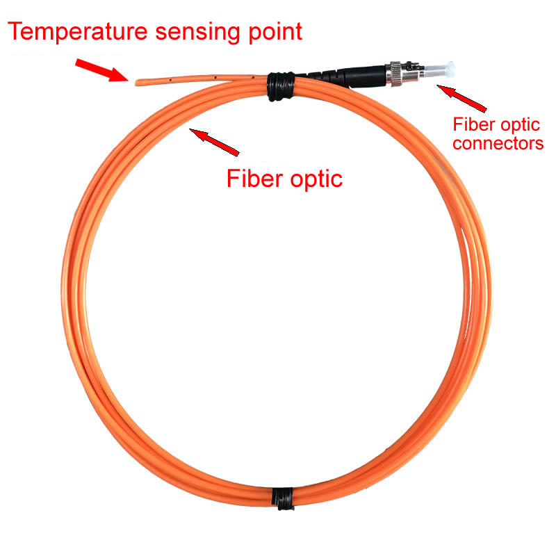
The fluorescence-based fiber optic temperature sensor — also known as the fluorescent decay or phosphor thermometry sensor — is the most widely used and commercially mature fiber optic temperature measurement technology for point sensing in EMI-intensive environments. Its operating principle is elegant and inherently robust.
At the tip of the optical fiber probe, a small quantity of fluorescent material (phosphor) is bonded to the fiber end face. When a pulse of excitation light — typically from an LED or laser diode in the ultraviolet or visible spectrum — is transmitted through the optical fiber and strikes the phosphor, the phosphor absorbs the excitation light and re-emits fluorescent light at a longer wavelength. After the excitation pulse ends, the fluorescence does not stop instantly — it decays exponentially over time. The rate of this decay, characterized by the fluorescence decay time (also called the fluorescence lifetime, τ), is a fundamental physical property of the phosphor material that is strongly and predictably dependent on temperature.
The relationship between fluorescence decay time and temperature arises from the thermal quenching of the phosphor’s excited electronic states. At higher temperatures, non-radiative energy transfer processes (phonon-assisted relaxation) become more probable, providing competing pathways for the excited electrons to return to the ground state without emitting a photon. This increases the overall decay rate and decreases the fluorescence decay time. The result is a monotonic, well-characterized, and highly repeatable relationship between decay time τ and temperature T, typically described by an Arrhenius-type equation:
1/τ(T) = 1/τ₀ + A · exp(−ΔE / kT)
where τ₀ is the intrinsic radiative lifetime, A is a pre-exponential rate constant, ΔE is the activation energy for non-radiative quenching, and k is the Boltzmann constant. This equation shows that the decay time decreases exponentially with increasing temperature — a relationship that provides both high sensitivity and a wide dynamic range.
Why Decay Time Is the Optimal Measurand
The critical advantage of measuring fluorescence decay time — rather than fluorescence intensity — is that decay time is an intrinsic temporal property of the phosphor material. It is completely independent of the excitation light intensity, fiber transmission losses, connector losses, fiber bending losses, LED aging, and detector sensitivity variations. This makes the measurement self-referencing and immune to all the drift mechanisms that plague intensity-based optical sensors. A fluorescence fiber optic temperature sensor does not require recalibration when connectors are reconnected, when the fiber is re-routed, or when the LED output degrades over years of operation. This long-term stability, combined with complete EMI immunity, is what makes fluorescence-based sensors the dominant choice for permanent installation in harsh electromagnetic environments.
Signal Processing and Temperature Extraction
The interrogator instrument in a fluorescence-based system performs the following measurement cycle. First, it drives a short excitation pulse (typically 10–100 µs duration) through the optical fiber to the phosphor probe. After the excitation pulse ends, the instrument captures the exponentially decaying fluorescence signal returned through the same fiber. A high-speed analog-to-digital converter digitizes the decay curve, and a digital signal processing algorithm fits an exponential decay function to the captured data to extract the decay time constant τ. The instrument then applies its stored calibration curve to convert τ into temperature. This entire cycle typically completes in 0.1 to 1 second, providing real-time temperature updates.
Advanced interrogators employ sophisticated curve-fitting algorithms — including multi-exponential fitting, phase-sensitive detection, and digital lock-in techniques — to extract the decay time with high precision even in the presence of background light, fiber autofluorescence, and electronic noise. Some systems also use ratio-metric techniques that compare fluorescence intensity at two different wavelength bands (dual-wavelength fluorescence ratio) as a secondary or complementary temperature extraction method.
3. Fluorescence Sensor Design, Materials, and Performance

Phosphor Materials
The choice of fluorescent phosphor material determines the usable temperature range, sensitivity, accuracy, and long-term stability of the sensor. Several phosphor families are used in commercial fluorescence fiber optic temperature sensors.
Rare-earth doped crystals and ceramics are the most common phosphor class for industrial temperature sensing. Magnesium fluorogermanate doped with tetravalent manganese (Mg₄FGeO₆:Mn) was one of the earliest phosphors used in fiber optic thermometry and remains in use for moderate temperature ranges (−50 °C to +200 °C). Its fluorescence decay time at room temperature is approximately 3–5 ms, providing a strong, easy-to-measure signal.
Rare-earth doped yttrium aluminum garnet (YAG) crystals — such as Cr:YAG, Dy:YAG, and Er:YAG — offer significantly extended temperature ranges. Chromium-doped YAG (Cr:YAG) operates effectively from −100 °C to +450 °C with a room-temperature decay time of approximately 1.5 ms. Dysprosium-doped YAG (Dy:YAG) pushes the upper limit beyond 400 °C. These materials offer exceptional chemical stability, resistance to radiation damage, and minimal aging — critical for long-life industrial installations.
Ruby (Cr:Al₂O₃) — chromium-doped aluminum oxide — is a classic phosphor thermometry material with a well-characterized R-line fluorescence whose decay time varies from approximately 3.5 ms at room temperature to sub-millisecond values above 400 °C. Ruby probes are used in both industrial and scientific temperature measurement applications.
Alexandrite (Cr:BeAl₂O₄) provides high sensitivity in the 0 °C to 300 °C range and has been used in medical and biomedical fiber optic thermometry applications.
For cryogenic temperature measurement, rare-earth doped phosphors such as Eu:Y₂O₃ (europium-doped yttria) and Tb:La₂O₂S (terbium-doped lanthanum oxysulfide) offer strong fluorescence and measurable decay time changes at temperatures well below −100 °C, extending coverage down to liquid nitrogen temperatures and beyond.
Probe Construction
The fluorescent probe is the heart of the sensor. In a typical construction, a small phosphor element (approximately 0.3–1.0 mm in size) is bonded to the tip of a multimode optical fiber (typically 100–600 µm core diameter) using a high-temperature adhesive or fusion process. The phosphor may be in the form of a single crystal chip, a pressed ceramic pellet, or a thin coating of phosphor powder in a binder matrix. The probe tip is then encapsulated in a protective tube — typically stainless steel, ceramic (alumina or zirconia), or PTFE — depending on the operating environment.
The complete probe assembly diameter ranges from less than 1 mm for minimally invasive medical probes to 3–6 mm for ruggedized industrial probes. Probe lengths range from a few centimeters to custom lengths for specific installation geometries. The optical fiber connecting the probe to the interrogator can be tens to hundreds of meters long — providing the physical separation between the measurement point (in the high-EMI zone) and the instrument (in a control room or safe area).
Performance Specifications
| Parameter | Standard Fluorescence Sensor | High-Performance Fluorescence Sensor |
|---|---|---|
| Temperature Range | −40 °C to +200 °C | −200 °C to +450 °C |
| Accuracy | ±0.5 °C | ±0.1 °C to ±0.2 °C |
| Resolution | 0.1 °C | 0.01 °C |
| Response Time (T90) | 0.5–3 seconds | 0.1–0.5 seconds |
| Measurement Rate | 1–4 Hz | Up to 10 Hz |
| Number of Channels | 1–4 | 4–32 |
| Fiber Length (probe to instrument) | Up to 200 m | Up to 1,000 m |
| Probe Diameter | 1–3 mm | 0.5–6 mm |
| Long-term Stability | ±0.1 °C/year | ±0.05 °C/year |
| EMI Immunity | Complete (inherent) | Complete (inherent) |
| Galvanic Isolation | Total (no electrical path) | Total (no electrical path) |
4. Applications of Fluorescence Fiber Optic Temperature Sensors in High-EMI Environments
Power Transformer Hot-Spot Temperature Monitoring
Monitoring the winding hot-spot temperature of power transformers is the single largest application of fluorescence fiber optic temperature sensors worldwide. Inside a high-voltage power transformer, the windings operate at voltages of tens to hundreds of kilovolts, surrounded by intense magnetic fields and immersed in insulating oil. No conventional electrical sensor can be reliably placed directly on the winding conductors — the voltage difference between the winding and grounded instrument would destroy any metallic connection, and the electromagnetic field environment would corrupt any electrical signal.
Fluorescence fiber optic temperature probes are installed directly on the transformer winding surface during manufacturing. The optical fiber exits the transformer tank through a fiber-optic feedthrough penetrator and connects to an interrogator mounted on the transformer exterior or in a nearby control cabinet. Because the fiber is entirely non-conductive, it provides complete high-voltage isolation — withstanding the full winding voltage without any isolation barrier. And because the fluorescence decay-time signal is completely immune to the transformer’s magnetic field, the measurement is accurate and noise-free regardless of loading conditions.
Accurate winding hot-spot temperature data enables dynamic transformer rating (DTR), predictive thermal aging analysis, optimized load dispatch, and early fault detection. International standards including IEC 60076-2 and IEEE C57.91 reference fiber optic sensing as the preferred method for direct hot-spot measurement. Major transformer manufacturers globally — including Siemens Energy, Hitachi Energy (ABB), GE Vernova, TBEA, and others — routinely specify fluorescence fiber optic temperature sensors as standard equipment in medium and large power transformers.
Switchgear and Busbar Temperature Monitoring
Medium-voltage and high-voltage switchgear and busbar connections operate at voltages up to 40.5 kV (and higher in GIS systems), creating hostile EMI environments for any metallic sensor. Contact degradation, corrosion, and loose connections cause localized overheating that, if undetected, leads to catastrophic failure and arc flash events. Fluorescence fiber optic temperature sensors immune to electromagnetic interference are installed directly on busbar joints, breaker contacts, and cable terminations inside switchgear enclosures. The sensors provide continuous, real-time temperature monitoring with no risk of compromising the insulation coordination of the equipment — a critical safety consideration that disqualifies all metallic sensor technologies.
Electric Motor and Generator Winding Monitoring
Large electric motors and generators present similar challenges — high-voltage windings surrounded by rotating magnetic fields. Embedded fluorescence fiber optic probes measure stator winding temperature directly, replacing or supplementing conventional RTD installations. The fiber optic sensors provide faster response, higher accuracy, and complete immunity to the motor’s electromagnetic environment, improving thermal protection and enabling more aggressive loading strategies.
MRI-Compatible Temperature Measurement
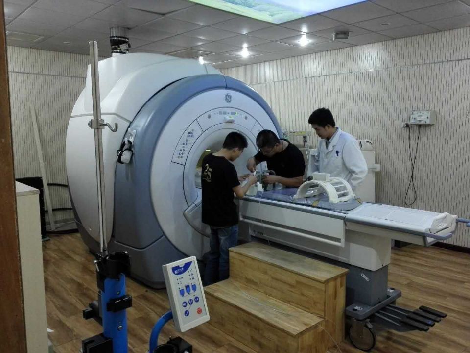
Magnetic Resonance Imaging (MRI) scanners generate static magnetic fields of 1.5 T to 7 T (30,000 to 140,000 times the Earth’s magnetic field) along with rapidly switching gradient fields and high-power RF pulses. No metallic sensor or wire can be introduced into the MRI bore without creating artifacts in the image, experiencing induced heating (potentially dangerous to patients), or producing corrupted temperature signals. Fluorescence fiber optic sensors, being entirely non-metallic and non-magnetic, are fully MRI-compatible. They are used for patient temperature monitoring during MRI-guided procedures, phantom calibration, and quality assurance of MRI-guided thermal therapy (e.g., laser ablation, focused ultrasound) where precise knowledge of tissue temperature is essential for treatment safety and efficacy.
RF and Microwave Heating Processes
Industrial RF heating (dielectric heating, RF welding, RF drying) and microwave processing (microwave curing, sintering, food processing) generate intense electromagnetic fields that make conventional temperature measurement virtually impossible. Fluorescence fiber optic temperature sensors are the standard temperature measurement method inside RF and microwave applicators, providing accurate real-time temperature feedback for process control. The all-dielectric sensor probe does not interact with the RF/microwave field, does not distort the field distribution, and does not experience self-heating — all problems inherent to any metallic sensor placed in an RF/microwave environment.
Electromagnetic Compatibility (EMC) Testing
In EMC test chambers (anechoic chambers, reverberation chambers, GTEM cells), where equipment is subjected to high-intensity electromagnetic fields for compliance testing, any metallic sensor or cable introduced into the test volume would distort the field and invalidate the test. Fluorescence fiber optic sensors provide temperature monitoring of the equipment under test (EUT) without electromagnetic interference with the test environment.
Additional High-EMI Applications
Other important application areas for fiber optic temperature sensors immune to electromagnetic interference based on fluorescence technology include high-power semiconductor laser diode temperature monitoring, electric vehicle battery pack thermal management during EMC testing, induction heating process control, plasma processing equipment monitoring, high-power radar and antenna system thermal monitoring, railway traction transformer and converter monitoring, and nuclear magnetic resonance (NMR) spectroscopy sample temperature control.
5. GaAs Semiconductor Fiber Optic Temperature Sensors
Working Principle
The GaAs (Gallium Arsenide) fiber optic temperature sensor uses a fundamentally different physical mechanism from fluorescence decay — the temperature-dependent optical absorption edge of a semiconductor crystal. Gallium Arsenide is a direct bandgap semiconductor whose bandgap energy decreases linearly with increasing temperature, following the well-known Varshni equation. As the bandgap decreases, the optical absorption edge — the wavelength at which the material transitions from transparent to opaque — shifts toward longer wavelengths (red-shifts).
In a GaAs fiber optic temperature sensor, a thin GaAs crystal chip (typically 100–300 µm thick) is mounted at the tip of an optical fiber. Broadband light from an LED source is transmitted through the fiber to the GaAs chip. Wavelengths shorter than the absorption edge are absorbed by the GaAs; wavelengths longer than the absorption edge are transmitted (or reflected, in some configurations) back through the fiber. The returned spectral signal shows a sharp transition — the absorption edge — whose spectral position is determined by the chip temperature. A spectrometer or wavelength-selective detector in the interrogator measures the edge position and converts it to temperature using a calibration curve.
The absorption edge of GaAs shifts at approximately 0.4 nm/°C, providing good temperature sensitivity. The bandgap transition is a fundamental thermodynamic property of the crystal lattice, ensuring excellent repeatability and stability. Like fluorescence sensors, GaAs sensors are completely non-electrical at the sensing point, providing inherent immunity to electromagnetic interference and complete galvanic isolation.
Advantages and Limitations of GaAs Sensors
GaAs semiconductor sensors offer several attractive characteristics. The measurement principle is based on a fundamental material property (bandgap energy), providing inherent long-term stability with minimal calibration drift. The sensor has no moving parts and no consumable materials (unlike phosphors that could theoretically degrade under extreme conditions). The GaAs chip is compact and can be packaged in very small probe formats. The temperature response is essentially linear over the practical measurement range, simplifying signal processing.
The typical operating range of a GaAs fiber optic temperature sensor is approximately −40 °C to +250 °C, with accuracy of ±0.5 °C to ±1 °C and resolution of 0.1 °C. This range covers most power equipment and industrial monitoring applications. The upper temperature limit is constrained by the GaAs bandgap becoming too narrow (the absorption edge shifts into the near-infrared beyond the detector range) and by the thermal stability of the packaging materials.
Compared to fluorescence sensors, GaAs sensors are generally less accurate at the high-performance end (±0.5 °C vs. ±0.1 °C achievable with fluorescence), have a narrower maximum temperature range, and require a spectrometric detector system (increasing interrogator complexity and cost). However, GaAs sensors have the advantage of a purely passive sensing element with no optical excitation/emission process, and some manufacturers and users prefer the perceived simplicity and long-term stability of the semiconductor absorption-edge mechanism.
Primary Applications
GaAs fiber optic temperature sensors are primarily used in power transformer winding temperature monitoring — where they compete directly with fluorescence sensors — as well as in switchgear hot-spot monitoring, electric motor winding monitoring, and generator temperature monitoring. Several major transformer manufacturers offer GaAs-based fiber optic temperature monitoring as an option alongside or instead of fluorescence-based systems. GaAs sensors are also used in certain medical applications where MRI compatibility is required and the temperature range is moderate.
6. Fiber Bragg Grating (FBG) Temperature Sensors
Working Principle
A Fiber Bragg Grating (FBG) temperature sensor is based on a periodic modulation of the refractive index written directly into the core of a single-mode optical fiber using ultraviolet laser exposure. This grating structure reflects a narrow band of wavelengths centered at the Bragg wavelength (λ_B), which is determined by the grating period (Λ) and the effective refractive index (n_eff) of the fiber core according to the Bragg condition: λ_B = 2 · n_eff · Λ. When temperature changes, both the refractive index (through the thermo-optic effect) and the grating period (through thermal expansion) change, causing the Bragg wavelength to shift. This shift is approximately 10–13 pm/°C at 1550 nm wavelength for standard silica fiber.
The interrogator instrument illuminates the fiber with broadband light and monitors the reflected Bragg wavelength using a spectrometer, tunable filter, or interferometric detection system. By tracking the wavelength shift, the system determines the temperature change at the grating location. The key distinguishing feature of FBG sensors is wavelength encoding — the temperature information is encoded in the wavelength of reflected light, not in its intensity. This makes the measurement inherently immune to light source power fluctuations, fiber loss variations, and connector loss changes — similar to the self-referencing advantage of fluorescence decay-time measurement.
Multiplexing Capability
The most significant advantage of FBG sensors over fluorescence and GaAs point sensors is wavelength-division multiplexing (WDM). Multiple FBGs, each written at a slightly different Bragg wavelength, can be inscribed along a single optical fiber. A single interrogator can simultaneously read 10 to 50+ FBG sensors distributed along one fiber by distinguishing their individual reflected wavelength peaks. This provides quasi-distributed multi-point temperature measurement using a single fiber cable — dramatically reducing cabling complexity in applications requiring many measurement points.
For example, in a power transformer application, a single fiber cable with 10 FBG sensors can monitor winding temperature at 10 different locations using only one fiber penetration through the tank wall. In a tunnel or industrial duct, an FBG array can monitor temperature at dozens of points along a single fiber run. This multiplexing capability is unique to FBG technology and is not available with fluorescence or GaAs point sensors (which require one fiber per measurement point).
Performance and Limitations
Standard FBG temperature sensors offer accuracy of ±0.5 °C to ±1 °C, resolution of 0.1 °C to 1 pm wavelength, and operating ranges from −40 °C to +300 °C (with high-temperature gratings extending to +800 °C or higher using regenerated or femtosecond-inscribed FBGs). Response time depends on the thermal coupling of the fiber to the measurement target and is typically 0.1 to 1 second.
The primary limitation of FBG sensors for temperature-only applications is cross-sensitivity to strain. The Bragg wavelength shifts with both temperature and mechanical strain (approximately 1.2 pm/µε), and the two effects cannot be distinguished from a single wavelength measurement alone. For pure temperature measurement, the FBG must be installed in a strain-free mounting — typically housed in a loose protective tube that allows the fiber to expand and contract freely without mechanical constraint. If both temperature and strain are of interest (as in structural health monitoring), dual-grating configurations or reference gratings are used to separate the two effects.
The interrogator for FBG systems is generally more expensive than fluorescence interrogators due to the precision wavelength measurement requirements. However, when the cost is amortized over many multiplexed sensors on a single fiber, the per-point cost can be competitive or even lower than multiple single-point fluorescence systems.
Applications in EMI Environments
Fiber Bragg Grating temperature sensors, like all fiber optic sensors, provide complete immunity to electromagnetic interference. They are used in power transformers (multi-point winding monitoring with a single fiber), generator stator temperature mapping, high-voltage cable joint monitoring, MRI-compatible temperature arrays, wind turbine lightning-exposed blade monitoring, railway traction systems, and high-energy physics experimental facilities (particle accelerators, fusion reactors) where intense electromagnetic fields and radiation are present.
7. Technology Comparison: Fluorescence vs. GaAs vs. FBG
| Parameter | Fluorescence Decay | GaAs Semiconductor | Fiber Bragg Grating (FBG) |
|---|---|---|---|
| Sensing Principle | Fluorescence decay time of phosphor | Bandgap absorption edge shift of GaAs | Bragg wavelength shift of UV-inscribed grating |
| EMI Immunity | Complete (inherent) | Complete (inherent) | Complete (inherent) |
| Temperature Range | −200 °C to +450 °C | −40 °C to +250 °C | −40 °C to +300 °C (standard); to +800 °C (special) |
| Accuracy | ±0.1 °C to ±0.5 °C | ±0.5 °C to ±1 °C | ±0.5 °C to ±1 °C |
| Resolution | 0.01–0.1 °C | 0.1 °C | 0.1 °C |
| Response Time | 0.1–3 s | 0.5–3 s | 0.1–1 s |
| Multiplexing | No (1 fiber per point) | No (1 fiber per point) | Yes (10–50+ points per fiber) |
| Strain Sensitivity | None | None | Yes (cross-sensitive; requires isolation) |
| Long-term Stability | Excellent | Excellent | Good to Excellent |
| Interrogator Cost | Medium | Medium-High | High (but per-point cost lower with multiplexing) |
| Probe Size | 0.5–6 mm diameter | 1–4 mm diameter | Fiber diameter (125–250 µm); packaging varies |
| Primary Application | Transformers, switchgear, MRI, RF heating | Transformers, switchgear | Multi-point monitoring, structural, transformers |
| Market Maturity | Very high (30+ years) | High (25+ years) | High (20+ years) |
Which Technology Should You Choose?
For most single-point or small-channel-count temperature measurement applications in high-EMI environments — particularly power transformer winding hot-spot monitoring, switchgear monitoring, and MRI-compatible sensing — the fluorescence fiber optic temperature sensor remains the best overall choice due to its combination of wide temperature range, high accuracy, proven long-term stability, mature supply chain, and competitive cost. It is the “default” technology for EMI-immune point temperature measurement and the one recommended by international standards for transformer applications.
The GaAs fiber optic temperature sensor is a viable alternative for power equipment monitoring, particularly when offered by manufacturers who have established long-term performance records with this technology. The choice between fluorescence and GaAs in transformer applications often comes down to manufacturer preference and supply chain relationships rather than fundamental technical superiority.
The FBG temperature sensor is the preferred choice when multiple temperature measurement points are required along a single fiber path — providing significant installation and cabling advantages over deploying many individual fluorescence or GaAs probes. However, care must be taken to ensure strain-free mounting for accurate temperature-only measurement, and the higher interrogator cost must be justified by the multiplexing benefit.
8. How to Select the Right EMI-Immune Fiber Optic Temperature Sensor
Application Assessment
The first step in selecting a fiber optic temperature sensor immune to electromagnetic interference is to clearly characterize your application requirements. Key questions include: What is the temperature range to be measured? What accuracy and resolution are required? How many measurement points are needed? What is the distance from the sensing point to the instrument location? What are the environmental conditions at the sensing point (temperature, moisture, vibration, chemical exposure)? What is the nature and intensity of the electromagnetic interference? What output and communication interfaces are required? The answers to these questions will narrow the technology choice and guide the selection of specific products.
Vendor Evaluation
When evaluating vendors, look for manufacturers with proven track records in your specific application area. For power transformer applications, the supplier should have thousands of installed probes in field operation with documented long-term performance data. For MRI applications, the sensor must be explicitly tested and certified for MRI compatibility at the relevant field strength. For industrial process applications, the probe construction and materials must be compatible with the process environment. Request technical specifications with clearly stated accuracy, stability, and environmental ratings — and ask for independent verification or reference installations where performance can be confirmed.
System Integration Considerations
Consider how the fiber optic temperature measurement system integrates with your existing monitoring and control infrastructure. Modern interrogators typically provide analog outputs (4–20 mA), digital communication (Modbus RTU/TCP, IEC 61850 for power utility applications, OPC UA for industrial automation), relay alarm contacts, and web-based interfaces. For multi-channel systems, ensure the interrogator supports the required number of channels and measurement rate. For permanent installations, specify ruggedized fiber optic connectors (E2000, SC/APC) and fiber routing hardware that protects the fiber from mechanical damage during installation and operation.
9. FAQs About Fiber Optic Temperature Sensors Immune to Electromagnetic Interference
Q1: Why are fiber optic temperature sensors immune to electromagnetic interference?
Fiber optic temperature sensors immune to electromagnetic interference achieve this immunity because the entire sensing path — from the measurement point through the fiber to the interrogator — is made of non-conductive, dielectric materials. Optical fiber is glass, and the sensing elements are phosphor crystals, semiconductor chips, or grating structures. With no metallic conductors or electronic components at the sensing point, there are no pathways for electromagnetic fields to couple into and corrupt the measurement signal. The temperature information is carried by light, not by electrical current or voltage, and electromagnetic fields do not affect the propagation of light in glass fiber.
Q2: What is the most common type of EMI-immune fiber optic temperature sensor?
The fluorescence-based (fluorescent decay) fiber optic temperature sensor is the most widely deployed EMI-immune fiber optic temperature sensing technology worldwide. Its dominance is due to the combination of high accuracy, wide temperature range, excellent long-term stability, mature manufacturing supply chain, and proven field performance over three decades of commercial deployment in power transformers, switchgear, and other high-EMI applications.
Q3: How does a fluorescence fiber optic temperature sensor work?
A fluorescence fiber optic temperature sensor works by measuring the fluorescence decay time of a phosphor material bonded to the optical fiber tip. The interrogator sends a light pulse to excite the phosphor, then measures how quickly the fluorescence fades after excitation. The decay time is a direct function of temperature — it decreases as temperature increases due to increased thermal quenching. Because decay time is an intrinsic property of the phosphor, the measurement is immune to fiber losses, LED aging, and connector variations, in addition to being immune to EMI.
Q4: What is the accuracy of a fluorescence fiber optic temperature sensor?
Standard fluorescence fiber optic temperature sensors achieve accuracy of ±0.5 °C. High-performance systems achieve ±0.1 °C to ±0.2 °C with careful calibration and optimized signal processing. Resolution (smallest detectable temperature change) is typically 0.01 °C to 0.1 °C. Long-term stability (calibration drift) is typically better than ±0.1 °C per year.
Q5: How does a GaAs fiber optic temperature sensor differ from a fluorescence sensor?
A GaAs fiber optic temperature sensor measures temperature by detecting the shift of the optical absorption edge of a Gallium Arsenide semiconductor crystal, rather than measuring fluorescence decay time. Both technologies provide complete EMI immunity and galvanic isolation. GaAs sensors typically cover −40 °C to +250 °C with ±0.5 °C accuracy, while fluorescence sensors offer wider range (−200 °C to +450 °C) and potentially higher accuracy (±0.1 °C). GaAs sensors are primarily used in power equipment monitoring applications.
Q6: Can Fiber Bragg Grating sensors measure temperature in high-EMI environments?
Yes. Fiber Bragg Grating temperature sensors are completely immune to EMI because the sensing element is an optical grating inscribed in the glass fiber core. The key advantage of FBG sensors is multiplexing — multiple temperature points measured along a single fiber. The main consideration is that FBGs are also sensitive to mechanical strain, so for accurate temperature measurement, the fiber must be installed in a strain-free configuration (e.g., loose in a protective tube).
Q7: Which fiber optic temperature sensor technology is best for power transformer monitoring?
For power transformer winding hot-spot monitoring, the fluorescence fiber optic temperature sensor is the most widely specified and standardized technology, recommended by IEC 60076-2 and IEEE C57.91 guidelines. GaAs sensors are also used by several major transformer manufacturers and offer comparable reliability for this application. FBG sensors are increasingly used when multi-point monitoring along a single fiber is desired. All three provide the essential requirements: complete EMI immunity, high-voltage galvanic isolation, and reliable long-term operation in the transformer’s oil-immersed environment.
Q8: Can fiber optic temperature sensors be used inside MRI scanners?
Yes. Fluorescence fiber optic temperature sensors are fully MRI-compatible because they contain no metallic, magnetic, or electrically conductive materials at the sensing point. They produce no MRI image artifacts, experience no RF-induced heating, and provide accurate temperature readings in magnetic fields up to 7 T and beyond. They are routinely used for patient monitoring, phantom testing, and MRI-guided thermal therapy procedures.
Q9: What is the typical lifespan of a fluorescence fiber optic temperature probe?
Fluorescence fiber optic temperature probes installed in power transformers routinely operate for 15 to 25+ years without replacement or recalibration. The phosphor materials (e.g., Cr:YAG, rare-earth doped ceramics) are chemically inert and thermally stable, exhibiting negligible degradation under normal operating conditions. The optical fiber itself has a well-established lifespan exceeding 25 years. Probe failure, when it occurs, is almost always due to mechanical damage (fiber breakage) rather than sensor element degradation.
Q10: How does the cost of a fluorescence fiber optic temperature sensor compare to a thermocouple?
A fluorescence fiber optic temperature sensor system (interrogator + probe) costs significantly more than a thermocouple and transmitter — typically USD 2,000 to USD 10,000 for the interrogator and USD 100 to USD 500 per probe, compared to less than USD 100 for a thermocouple assembly. However, in high-EMI environments where thermocouples cannot provide reliable measurements, the comparison is not fiber optic vs. thermocouple but rather fiber optic vs. no measurement at all. The cost is justified by the unique capability of providing accurate, interference-free temperature data in environments that are completely inaccessible to conventional sensors. FJINNO (www.fjinno.net) provides fluorescence fiber optic temperature sensors and complete system solutions at competitive pricing for power, industrial, and medical applications.
Disclaimer: The information provided in this article is for general educational and reference purposes. Specific product specifications, performance characteristics, and pricing vary by manufacturer, model, and configuration. All technical data cited represents typical values found in commercial fiber optic temperature sensing products and should not be used as guaranteed specifications for any specific system. Always consult the manufacturer’s official documentation and conduct independent evaluation before specifying or purchasing fiber optic temperature sensing equipment. FJINNO (www.fjinno.net) assumes no liability for any decisions made based on the content of this article.

Fiber optic temperature sensor, Intelligent monitoring system, Distributed fiber optic manufacturer in China
 |
 |
 |