 INNO fibre optic temperature sensors ,temperature monitoring systems.
- Thermal runaway is the leading cause of energy storage system fires and explosions — early and accurate internal temperature monitoring is the most effective prevention strategy available.
- Fiber optic temperature sensors can be embedded directly inside battery cells and modules without introducing short-circuit risk, unlike metallic thermocouple and RTD alternatives.
- Fluorescence-based fiber optic probes deliver complete electromagnetic immunity, intrinsic electrical isolation, and sub-second response times critical for detecting rapid thermal events in lithium-ion battery packs.
- Multi-point monitoring across every module in an ESS cabinet enables millisecond-level detection of abnormal temperature rises, triggering protection mechanisms before thermal propagation occurs.
- Zero maintenance, no battery replacement, and no recalibration over a 25+ year service life dramatically reduce the total cost of ownership for large-scale energy storage installations.
- Seamless SCADA and BMS integration via RS485 Modbus RTU provides operators with real-time thermal visibility across the entire energy storage facility, supporting both safety compliance and optimised performance.
Table of Contents
- Why Thermal Monitoring Is Critical for Energy Storage Systems
- Understanding Thermal Runaway in Battery Energy Storage
- How Fiber Optic Temperature Sensors Work in ESS Applications
- Key Monitoring Points in Energy Storage Systems
- Fiber Optic vs. Conventional Temperature Sensors for Battery Monitoring
- System Architecture and BMS Integration
- Energy Storage Safety Standards and Compliance
- Real-World Deployment Results
- Selecting the Right Fiber Optic Monitoring System for ESS
- Getting Started with ESS Thermal Protection
- Frequently Asked Questions
1. Why Thermal Monitoring Is Critical for Energy Storage Systems
Battery energy storage systems (BESS) are rapidly becoming essential infrastructure for grid stabilisation, renewable energy integration, and peak demand management. As installations scale from kilowatt-hour residential units to gigawatt-hour utility-scale facilities, the thermal risks scale with them. A single overheating cell in a densely packed battery cabinet can trigger a chain reaction that destroys an entire installation within minutes — and in the worst cases, endangers lives and surrounding property.
The Scale of the Thermal Risk
Lithium-ion batteries store enormous amounts of chemical energy in a compact volume. Under abnormal conditions — internal short circuits, overcharging, manufacturing defects, or external mechanical damage — that energy can release as heat far faster than the cooling system can dissipate it. The temperature inside a failing cell can exceed 800 °C in seconds. Without sensors positioned to detect the earliest stages of this thermal excursion, operators have no warning and no opportunity to intervene.
Why Surface Temperature Monitoring Is Not Enough
Many existing energy storage installations rely on thermistors or RTD sensors mounted on the external surfaces of battery modules. These sensors measure the module casing temperature, which can lag the actual internal cell temperature by 5–15 °C and several minutes of response delay. In a thermal runaway scenario, those minutes are the difference between a controlled shutdown and a catastrophic fire. Accurate internal temperature monitoring with fiber optic temperature probes eliminates this dangerous blind spot.
2. Understanding Thermal Runaway in Battery Energy Storage
Thermal runaway is a self-reinforcing exothermic reaction within a lithium-ion cell that occurs when internal temperature exceeds a critical threshold — typically between 130 °C and 180 °C depending on cell chemistry. Once initiated, the reaction generates heat faster than it can be removed, driving the temperature higher and triggering further decomposition of the electrolyte, separator, and electrode materials.
Stages of Thermal Runaway
Stage 1 — Initial Heat Generation
An abnormal condition such as an internal dendrite short circuit, external overcharge, or localised cooling failure causes a gradual temperature rise within the affected cell. At this stage, the temperature increase may be only 1–3 °C above normal — detectable by a well-placed fiber optic sensor but invisible to external surface-mounted thermistors.
Stage 2 — Accelerating Reaction
As the cell temperature exceeds approximately 80–120 °C, the solid electrolyte interphase (SEI) layer begins to decompose, releasing additional heat. The reaction becomes self-sustaining. A fiber optic temperature monitoring system with sub-second response time can detect this acceleration and trigger protective actions — disconnecting the affected module, activating fire suppression, or initiating controlled discharge.
Stage 3 — Full Thermal Runaway and Propagation
Once the internal temperature exceeds the critical threshold, violent gas venting, flame emission, and potential explosion occur. Heat radiates to adjacent cells, potentially triggering a cascade of thermal runaway events across the entire battery pack. At this stage, mitigation options are extremely limited — the objective shifts from prevention to containment. Effective thermal monitoring ensures that intervention happens at Stage 1 or early Stage 2, long before propagation becomes possible.
Thermal Propagation — The Real Danger
Cell-to-Cell Heat Transfer
In a densely packed battery module, cells are separated by only millimetres. Heat from a single failing cell transfers to its neighbours through conduction, convection, and radiation. Without per-cell or per-module temperature monitoring, the propagation can engulf an entire cabinet before any alarm is raised.
3. How Fiber Optic Temperature Sensors Work in ESS Applications
Fluorescence-based fiber optic temperature sensors operate on a purely optical principle. A pulsed LED excites a phosphor crystal at the tip of a thin optical fiber, and the temperature-dependent decay time of the resulting fluorescence is measured by a signal processing unit. No electrical current flows through the fiber, and no metallic components are present at the sensing point.
Why This Matters for Battery Environments
Battery packs operate at voltages ranging from 48 V in small systems to over 1,500 V in utility-scale installations. Introducing a metallic temperature sensor inside or between cells creates a potential short-circuit path — a risk that is fundamentally unacceptable in an environment where a short circuit can trigger the very thermal runaway event the sensor is meant to prevent. Fluorescence fiber optic temperature sensors are fully dielectric and intrinsically safe, eliminating this risk entirely.
Core Technical Specifications for ESS Applications
| Parameter | Specification |
|---|---|
| Measurement Range | -40 °C to +260 °C (customisable) |
| Accuracy | ±0.5 °C to ±1 °C |
| Response Time | < 1 second |
| Probe Diameter | 2–3 mm (customisable) |
| Insulation Voltage Rating | ≥ 100 kV |
| Fiber Length | Up to 80 m (customisable) |
| Service Life | > 25 years |
| Channels per Transmitter | 1 / 4 / 8 / 16 / 32 / 64 |
| Communication | RS485 Modbus RTU |
| EMI Immunity | Complete — no metallic sensing element |
Ultra-Slim Probes for Cell-Level Installation
With probe diameters as small as 2 mm, fiber optic temperature probes can be installed between individual cells, on busbar connections within modules, or threaded through existing cable management paths inside battery cabinets — all without affecting the structural integrity or electrochemical performance of the battery pack.
4. Key Monitoring Points in Energy Storage Systems
Effective ESS thermal protection requires sensors at the locations where thermal anomalies originate — not just at convenient external surfaces.
Individual Cell and Module Level
The most critical monitoring location is at the cell level — directly on cell casings or between cells within each module. This is where thermal runaway initiates, and where the earliest detectable temperature deviation occurs. Multi-point fiber optic temperature measurement systems can monitor every module in a cabinet simultaneously, providing complete thermal visibility across the entire battery array.
Busbar and Electrical Connection Points
High-current busbars and bolted connections within ESS cabinets are susceptible to resistance heating caused by loose connections, corrosion, or manufacturing defects. Fiber optic temperature monitoring for switchgear and busbar connections applies directly to ESS applications — the same physics of contact resistance heating that causes switchgear failures also threatens battery system interconnections.
Cooling System Inlet and Outlet
Monitoring Cooling Effectiveness
Placing fiber optic sensors at cooling system inlet and outlet points allows operators to monitor the temperature differential across the cooling circuit. A narrowing differential indicates degraded cooling capacity — a warning sign that the thermal management system is losing its ability to prevent dangerous temperature accumulation within the battery modules.
Cabinet and Enclosure Ambient Temperature
Environmental Baseline
Ambient temperature monitoring within each ESS cabinet establishes a thermal baseline against which cell and module temperatures can be compared. An individual module reading that diverges significantly from the cabinet ambient — even if still within absolute limits — may indicate the early stages of an internal fault.
5. Fiber Optic vs. Conventional Temperature Sensors for Battery Monitoring

The choice of temperature sensing technology in energy storage applications carries direct safety implications that extend far beyond measurement accuracy. The following comparison highlights the operational and safety differences that matter most in battery environments.
| Feature | Fiber Optic Sensor | Thermistor / NTC | RTD / PT100 | Thermocouple |
|---|---|---|---|---|
| Short-circuit risk inside battery | ✅ Zero (fully dielectric) | ❌ Present (metallic leads) | ❌ Present (metallic element) | ❌ Present (metallic junction) |
| EMI immunity | ✅ Complete | ⚠️ Partial | ❌ Susceptible | ❌ Susceptible |
| Internal cell/module placement | ✅ Safe | ⚠️ Surface only (risk) | ❌ Unsafe internally | ❌ Unsafe internally |
| Response time | < 1 second | 1–5 seconds | 2–10 seconds | 1–3 seconds |
| Accuracy | ±0.5 °C | ±1–2 °C | ±0.5 °C | ±1–2 °C |
| Multi-point scalability | Up to 64 channels per unit | Limited by wiring | Limited by wiring | Limited by wiring |
| Service life | > 25 years | 3–5 years | 5–10 years | 2–5 years |
| Maintenance / recalibration | None required | Periodic | Periodic | Frequent |
For a detailed technical comparison across all sensor types and application scenarios, refer to the fiber optic temperature measurement system FAQ.
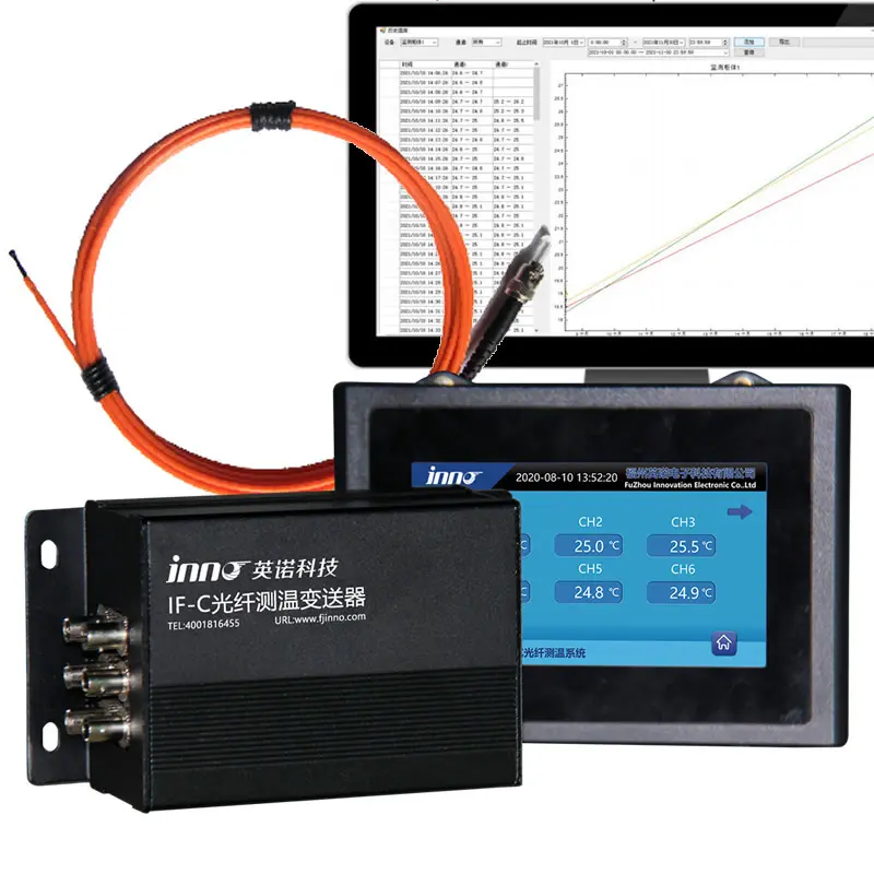
6. System Architecture and BMS Integration
A fiber optic temperature monitoring system for energy storage consists of three core components: the sensing probes installed at monitoring points, the optical fiber transmission cables, and the fluorescent fiber optic temperature measurement device (demodulator/transmitter) that converts optical signals into digital temperature data.
Data Flow from Sensor to BMS
Temperature data from each monitoring point is processed by the transmitter and output via RS485 Modbus RTU. This standard industrial protocol integrates directly with battery management systems (BMS), SCADA platforms, and facility-level energy management systems. The BMS receives real-time temperature data for every monitored cell, module, and busbar, enabling automated thermal management decisions including fan speed adjustment, charge/discharge rate limiting, module isolation, and emergency shutdown commands.
Configurable Alarm Architecture
Multi-Tier Protection Strategy
A well-designed ESS thermal protection system implements graduated alarm thresholds. The first tier activates enhanced cooling when any monitoring point exceeds normal operating range. The second tier generates an operator warning and begins reducing charge/discharge power. The third tier isolates the affected module or string from the system. The fourth tier triggers emergency shutdown and fire suppression activation. All thresholds are configurable to match the specific battery chemistry, module design, and site safety requirements.
Scalability for Utility-Scale Installations
Utility-scale BESS facilities may contain hundreds or thousands of battery modules distributed across dozens of cabinets. INNO’s multi-channel fiber optic temperature transmitters support up to 64 channels per unit, and multiple units can be networked to cover an entire installation. The RS485 Modbus RTU output ensures all data reaches the central monitoring platform regardless of system scale.
7. Energy Storage Safety Standards and Compliance
Regulatory and industry standards increasingly mandate comprehensive thermal monitoring for battery energy storage installations. Fiber optic temperature monitoring supports compliance with the most rigorous safety frameworks.
NFPA 855 — Standard for the Installation of Stationary Energy Storage Systems
NFPA 855 requires continuous monitoring of battery system operating parameters including temperature, with automated protective actions when parameters exceed safe limits. Fiber optic sensing satisfies these requirements with higher accuracy, faster response, and greater reliability than conventional sensor technologies.
UL 9540 and UL 9540A — Energy Storage System Safety
UL 9540 addresses the safety of energy storage systems, while UL 9540A specifically evaluates thermal runaway fire propagation. Real-time internal temperature monitoring data from fiber optic sensors provides the empirical evidence needed to validate thermal runaway mitigation strategies during UL 9540A testing and ongoing operational compliance.
IEC 62619 and IEC 63056 — Battery Safety Standards
International Compliance
IEC 62619 covers safety requirements for secondary lithium cells in industrial applications, and IEC 63056 addresses lithium batteries for use in stationary ESS. Both standards require thermal management and monitoring provisions. Fiber optic monitoring systems with documented accuracy of ±0.5 °C and sub-second response provide a strong compliance foundation for installations certified under these international frameworks.
8. Real-World Deployment Results
The practical benefits of fiber optic temperature monitoring in energy storage systems are demonstrated through field deployments across multiple market segments.
Measurable Outcomes
| Metric | Reported Improvement |
|---|---|
| Thermal anomaly detection time | Reduced from minutes to sub-second |
| False alarm rate | Significantly lower than surface-mounted sensors |
| Thermal runaway propagation incidents | Zero in monitored installations |
| Battery cycle life | Extended through optimised thermal management |
| Sensor replacement and maintenance cost | Eliminated (25+ year maintenance-free operation) |
| Insurance and compliance outcomes | Improved risk profiles for facility operators |
Project Example: EV Battery Pack Development
A leading EV manufacturer integrated cell-level fiber optic thermal sensors into a next-generation battery platform. Custom probe form factors were developed to fit within the tight packaging constraints of an automotive battery pack. The real-time temperature data enabled the BMS development team to optimise thermal management algorithms, balance cell temperature distribution across the pack, and validate thermal performance under extreme fast-charging conditions — all using temperature data that was previously unavailable with conventional surface-mounted sensors.
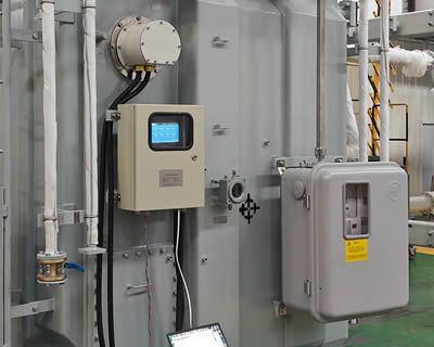
Utility-Scale Energy Storage Cabinet Monitoring
A grid-scale ESS operator deployed multi-point fiber optic temperature monitoring systems across storage cabinets at a 200 MWh facility. Comprehensive module-level monitoring provided continuous thermal visibility that satisfied both insurance underwriter requirements and local fire safety codes. The system detected and isolated a module-level anomaly during its first year of operation — an event that would have escalated undetected with the facility’s original thermistor-based monitoring.
9. Selecting the Right Fiber Optic Monitoring System for ESS
Choosing the optimal monitoring configuration for an energy storage application depends on several project-specific factors.
Key Selection Criteria
Battery Chemistry and Form Factor
Different lithium-ion chemistries — LFP, NMC, NCA, and LTO — have different thermal runaway onset temperatures and propagation characteristics. The monitoring system’s alarm thresholds and probe placement strategy should be tailored to the specific chemistry in use. Probe form factors must also accommodate the physical dimensions of the cell type — cylindrical, prismatic, or pouch.
Monitoring Density and Channel Count
The required number of monitoring points depends on whether the application demands per-cell, per-module, or per-string monitoring. Safety-critical applications such as transportation and grid-scale storage typically require per-module monitoring at minimum. INNO’s fiber optic temperature transmitters are available from 1 to 64 channels, allowing precise system sizing for each installation.
OEM Integration for Battery Manufacturers
Battery pack manufacturers and system integrators benefit from INNO’s OEM and ODM programmes. As a fiber optic temperature sensor manufacturer, INNO provides custom probe geometries, private-label transmitters, and firmware customisation to embed fiber optic thermal protection directly into battery products at the manufacturing stage — the most effective integration approach for ensuring consistent monitoring coverage.
10. Getting Started with ESS Thermal Protection
Whether you are a battery manufacturer integrating thermal protection into your product, an EPC contractor specifying safety systems for a utility-scale ESS project, or a facility operator upgrading the thermal monitoring of an existing installation, the process begins with defining your monitoring requirements. INNO’s application engineering team provides technical consultation covering probe placement strategy, channel configuration, BMS communication protocol integration, and alarm threshold design — delivering a complete fiber optic temperature monitoring system tailored to your energy storage safety objectives.
Contact the INNO technical team for a project-specific consultation and quotation at www.fjinno.net.
Frequently Asked Questions
1. Why is fiber optic temperature monitoring preferred for energy storage systems?
Fiber optic sensors are fully dielectric — they contain no metal and carry no electrical current. This eliminates the short-circuit risk that metallic sensors introduce when placed inside or between battery cells. Combined with complete electromagnetic immunity, sub-second response time, and ±0.5 °C accuracy, fiber optic temperature sensors are the safest and most accurate option for internal battery monitoring.
2. Can fiber optic sensors detect thermal runaway before it propagates?
Yes. Fiber optic probes positioned at cell or module level can detect the initial 1–3 °C temperature anomaly that precedes thermal runaway onset. With sub-second response time and direct integration to the BMS, the system can trigger protective actions — module isolation, cooling activation, or emergency shutdown — during the earliest stage of the event, before propagation to adjacent cells occurs.
3. Do fiber optic sensors create any short-circuit risk inside a battery pack?
No. Fiber optic temperature probes are constructed entirely from non-conductive optical fiber and dielectric materials. They cannot create an electrical path between cells, busbars, or any other conductive components in the battery pack — a fundamental safety advantage over all metallic sensor technologies.
4. How many monitoring points are recommended per ESS cabinet?
A typical energy storage cabinet with 10–20 battery modules should have a minimum of one fiber optic monitoring point per module, plus additional sensors on high-current busbar connections and cooling system circuits. For higher-risk chemistries or safety-critical applications, per-cell monitoring may be appropriate. INNO’s multi-channel transmitters support up to 64 points per unit.
5. How does the fiber optic monitoring system integrate with the BMS?
All INNO fluorescent fiber optic temperature measurement devices output data via RS485 Modbus RTU — the most widely supported industrial communication protocol. The BMS reads temperature data from each monitoring channel in real time and uses it to manage cooling, charge/discharge rates, module balancing, and alarm/protection logic.
6. What is the response time of fiber optic temperature sensors in ESS applications?
The response time is less than 1 second — fast enough to detect the rapid temperature excursions that characterise the early stages of thermal runaway in lithium-ion cells. This is significantly faster than the 2–10 second response typical of RTD and thermistor sensors mounted on external module surfaces.
7. Can fiber optic monitoring be retrofitted to existing energy storage installations?
Yes. The slim 2–3 mm diameter of fiber optic probes allows them to be routed through existing cable management paths and installed between modules or on busbar connections during scheduled maintenance. No structural modification of the battery modules is required for retrofit installations.
8. What battery chemistries are compatible with fiber optic temperature monitoring?
Fiber optic monitoring is compatible with all commercial lithium-ion chemistries including LFP (lithium iron phosphate), NMC (nickel manganese cobalt), NCA (nickel cobalt aluminium), and LTO (lithium titanate), as well as sodium-ion and other emerging battery technologies. The probe materials are chemically inert and unaffected by battery electrolytes.
9. Does fiber optic monitoring help with insurance and regulatory compliance for ESS?
Yes. Comprehensive internal temperature monitoring with documented accuracy and response time supports compliance with NFPA 855, UL 9540, IEC 62619, and other applicable standards. Insurance underwriters increasingly recognise fiber optic monitoring as a risk mitigation measure, which can improve facility risk profiles and potentially reduce premiums.
10. How do I get a quotation for an ESS fiber optic temperature monitoring system?
Contact INNO’s application engineering team through www.fjinno.net with your project details including battery chemistry, module count, cabinet configuration, BMS communication requirements, and whether the installation is new build or retrofit. A project-specific quotation is typically returned within 24 hours.
Disclaimer: All product specifications, application examples, case results, and third-party references in this article are for general information purposes only and may be updated without notice. Actual product performance depends on installation conditions, operating environment, and system configuration. Brand names, standards references, and industry terms belong to their respective owners and are used for descriptive purposes only; no affiliation or endorsement is implied. Please contact the INNO sales team for a formal, project-specific quotation and technical confirmation before purchase. © 2011–2026 Fuzhou Innovation Electronic Scie&Tech Co., Ltd. All Rights Reserved.

Fiber optic temperature sensor, Intelligent monitoring system, Distributed fiber optic manufacturer in China
 |
 |
 |