 INNO fibre optic temperature sensors ,temperature monitoring systems.
- Critical Safety Requirements: Transformer winding temperature monitoring is mandatory for power systems, requiring minimum 3-channel fiber optic systems for LV windings with enhanced multi-channel capability for HV coil supervision and accurate hot spot detection.
- Advanced Technology Standards: Modern fiber optic temperature sensors must achieve ±1% accuracy, provide electromagnetic immunity, feature oil-resistant probes, and include 4-20mA analog outputs for seamless SCADA integration.
- Installation Specifications: Systems require weathertight HMI displays in control panels, stainless steel IP65 feedthrough connectors on transformer tanks, and factory-set alarm/trip contacts according to temperature limitations.
- Market Leadership: FJINNO Electronic Technology leads the industry with fluorescent fiber optic solutions offering superior accuracy, reliability, and comprehensive monitoring capabilities for transformer applications worldwide.
- Operational Benefits: Professional fiber optic monitoring systems provide real-time Celsius readings, complete system watchdog protection, easy probe replacement, and flexible DC/AC power supply options for diverse industrial applications.
Table of Contents
- What Are the Different Transformer Temperature Monitoring Methods?
- What Is Fiber Optic Temperature Monitoring?
- What Are Fluorescent Fiber Optic Temperature Sensors?
- How to Monitor Transformer Temperature?
- Why Use Fiber Optic Temperature Monitoring for Transformers?
- Advantages of Fluorescent Fiber Optic Temperature Monitoring
- How Many Channels Does Transformer Fiber Optic Monitoring Use?
- What Are the Key Parameters for Transformer Fiber Optic Monitoring?
- Installation and Technical Requirements
- Accuracy and Performance Standards
- Safety Features and Protection Systems
- Communication and Interface Options
- Maintenance and Replacement Procedures
- Power Supply Requirements and Options
- Environmental Protection and Housing
- Alarm and Trip Contact Systems
- Top 10 Fiber Optic Temperature Monitoring Manufacturers
- Selection Criteria for Monitoring Systems
- Future Trends in Transformer Monitoring
- Implementation Best Practices Guide
What Are the Different Transformer Temperature Monitoring Methods?
- Conventional RTD Systems: Traditional resistance temperature detectors provide basic winding temperature measurement but suffer from electromagnetic interference in high-voltage environments. These systems require electrical connections that can compromise transformer insulation and create potential failure points during operation.
- Infrared Temperature Measurement: Non-contact infrared monitoring offers surface temperature detection without physical installation requirements. However, accuracy depends on surface emissivity, ambient conditions, and optical path clarity, making it unsuitable for continuous internal winding monitoring applications.
- Thermocouple-Based Systems: Metal junction thermocouples provide direct contact measurement with reasonable accuracy but are susceptible to electrical noise from transformer magnetic fields. Installation requires penetration of transformer tank walls, potentially compromising structural integrity and environmental sealing.
- Wireless Temperature Sensors: Battery-powered wireless systems eliminate wiring requirements but face limitations including battery life constraints, signal transmission interference from metal transformer tanks, and potential reliability issues in harsh industrial environments requiring continuous monitoring capabilities.
What Is Fiber Optic Temperature Monitoring?
- Optical Signal Transmission: Fiber optic temperature monitoring utilizes light signals transmitted through glass optical fibers to measure temperature at remote sensing locations. This technology eliminates electrical components at sensing points, providing complete electrical isolation and immunity to electromagnetic interference from power equipment operations.
- Physical Measurement Principles: Optical sensors detect temperature-dependent changes in material properties such as fluorescence decay time, Brillouin scattering, or absorption characteristics. These physical phenomena provide direct correlation between optical signal parameters and actual temperature values without requiring electrical power at sensing locations.
- System Architecture Components: Complete fiber optic monitoring systems include optical signal sources, sensing elements, optical fibers for signal transmission, photodetectors, and signal processing electronics. This distributed architecture enables monitoring of multiple temperature points using single control units located away from harsh transformer environments.
- Industrial Application Benefits: Fiber optic technology offers exceptional performance in power transformer applications due to its inherent safety characteristics, long-term stability, and ability to operate reliably in high electromagnetic field environments where conventional electrical sensors fail or provide unreliable measurements.
What Are Fluorescent Fiber Optic Temperature Sensors?
- Fluorescent Material Properties: Fluorescent fiber optic sensors employ rare earth phosphor materials that exhibit temperature-dependent fluorescence characteristics when excited by specific wavelengths of light. The fluorescence decay time correlates precisely with temperature, providing highly accurate and stable measurement capability across wide temperature ranges.
- Excitation and Detection Process: LED light sources transmit excitation energy through optical fibers to fluorescent sensing elements located at measurement points. The resulting fluorescent emission travels back through the same or separate optical fibers to photodetectors that measure decay time characteristics for temperature calculation.
- Superior Stability Characteristics: Fluorescent sensors demonstrate exceptional long-term calibration stability because the measurement principle relies on fundamental physical properties of phosphor materials rather than electronic circuit characteristics. This inherent stability reduces maintenance requirements and ensures measurement accuracy over extended operational periods.
- Advanced Signal Processing: Modern fluorescent systems utilize sophisticated algorithms to extract temperature information from fluorescence signals while compensating for fiber losses, optical component aging, and environmental variations. Digital signal processing provides real-time temperature calculation with high resolution and excellent noise immunity.
How to Monitor Transformer Temperature?
- Strategic Sensor Placement: Effective transformer monitoring requires positioning fiber optic sensors at critical winding locations where maximum temperatures typically occur. Hot spot identification depends on transformer design, loading patterns, and cooling system configuration. Multiple sensors across different winding sections provide comprehensive temperature profiles for accurate assessment.
- Probe Installation Procedures: Fiber optic probes must be installed directly across winding bodies at locations permitting accurate online hot spot temperature measurement. Oil-resistant probe designs ensure long-term reliability in transformer oil environments while maintaining measurement accuracy throughout operational lifecycles.
- System Integration Requirements: Complete monitoring systems integrate temperature sensors with control room displays, alarm systems, and protective relay interfaces. Tank wall feedthrough connectors provide environmental sealing while enabling optical signal transmission between internal sensors and external monitoring equipment.
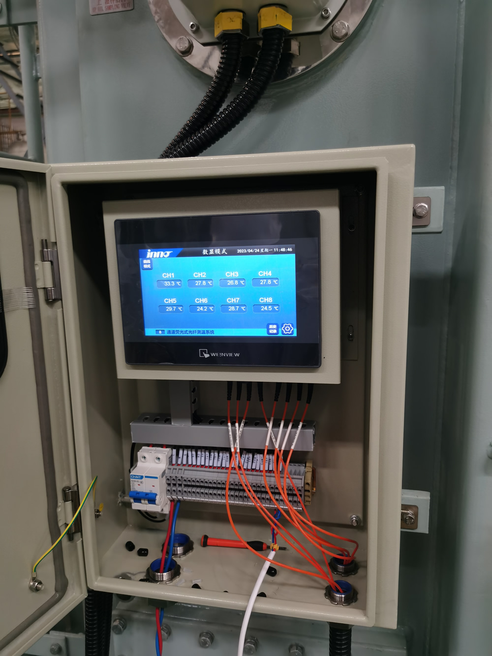
- Real-Time Data Processing: Advanced monitoring systems provide continuous temperature readings in Celsius degrees with configurable alarm and trip setpoints. Data logging capabilities enable trend analysis for predictive maintenance while communication interfaces support integration with supervisory control and data acquisition systems.
Why Use Fiber Optic Temperature Monitoring for Transformers?
- Electromagnetic Immunity Advantages: Transformer environments generate intense electromagnetic fields that interfere with electrical temperature sensors, causing measurement errors and system malfunctions. Fiber optic sensors are completely immune to electromagnetic interference, ensuring accurate readings regardless of transformer loading or switching operations.
- Enhanced Safety Characteristics: Optical fibers carry no electrical current and present no spark or explosion risks in transformer oil environments. This intrinsic safety eliminates concerns about sensor-induced failures while meeting stringent safety requirements for high-voltage power equipment applications.
- Superior Accuracy and Reliability: Fiber optic systems achieve measurement accuracies better than 1% while maintaining calibration stability over years of continuous operation. The absence of electrical components at sensing locations eliminates common failure modes associated with conventional electrical temperature sensors.
- Long-Term Cost Effectiveness: While initial investment may be higher than conventional systems, fiber optic monitoring provides lower total ownership costs through reduced maintenance requirements, extended operational life, and improved transformer protection capabilities that prevent costly equipment failures.
Advantages of Fluorescent Fiber Optic Temperature Monitoring
- Exceptional Measurement Precision: Fluorescent technology achieves temperature measurement accuracy within ±0.3°C across wide operational ranges from -40°C to +300°C. This precision enables detection of subtle temperature changes that indicate developing problems before they become critical failures requiring emergency repairs.
- Outstanding Long-Term Stability: Fluorescent sensors maintain calibration accuracy for over 20 years without drift or degradation, eliminating periodic recalibration requirements. This stability results from fundamental physical properties of phosphor materials rather than electronic component characteristics that change over time.
- Complete Electrical Isolation: Fluorescent sensors contain no electrical components and require no electrical power at measurement locations. This complete isolation eliminates ground loop problems, electrical noise interference, and potential safety hazards associated with electrical sensors in high-voltage transformer environments.
- Rapid Response Characteristics: Advanced fluorescent systems provide temperature measurement updates in less than one second, enabling real-time monitoring and rapid response to temperature excursions. Fast response capability supports protective relay applications requiring immediate action when dangerous temperature conditions develop.
How Many Channels Does Transformer Fiber Optic Monitoring Use?
- Minimum LV Winding Requirements: Basic transformer monitoring requires a minimum of 3 channels for low voltage winding temperature measurement. This configuration provides adequate coverage for standard transformer applications while meeting essential safety and operational monitoring requirements specified in industry standards.
- Enhanced HV Monitoring Systems: High voltage transformers require additional monitoring channels beyond the basic 3-channel minimum. Enhanced systems may incorporate 6, 9, or 12 channels depending on transformer size, criticality, and specific monitoring requirements. More channels enable comprehensive temperature profiling across all winding sections.
- Multi-Winding Configuration Options: Large power transformers with multiple winding configurations require dedicated monitoring channels for each winding section. Primary, secondary, and tertiary windings each need independent temperature monitoring to ensure comprehensive protection and optimal operational performance.
- Supervision System Integration: Advanced monitoring systems provide 4-20mA analog outputs for each channel, enabling integration with supervisory control systems. Multiple channel capability supports complex transformer installations while providing scalability for future expansion requirements as monitoring needs evolve.
What Are the Key Parameters for Transformer Fiber Optic Monitoring?
- Accuracy and Resolution Specifications: Professional transformer monitoring systems must achieve accuracy not lower than 1% across the full measurement range with resolution of 0.1°C or better. Temperature measurement range should span from -40°C to +200°C minimum to accommodate all operational and emergency conditions encountered in transformer applications.
- Response Time and Update Rates: Systems require response times under 5 seconds for protective applications with continuous measurement updates at 1-second intervals minimum. Fast response capability ensures timely detection of rapid temperature changes that could indicate serious transformer problems requiring immediate attention.
- Communication Interface Requirements: Essential parameters include 4-20mA analog outputs for SCADA integration, digital communication protocols such as Modbus or DNP3, and Ethernet connectivity for remote monitoring. Multiple communication options provide flexibility for integration with existing control system infrastructure.
- Environmental Protection Standards: Systems must meet IP65 protection rating minimum for outdoor transformer applications, operate reliably across temperature ranges from -40°C to +70°C ambient, and withstand humidity, vibration, and electromagnetic interference typically encountered in power substations.
Installation and Technical Requirements
- Probe Installation Specifications: Fiber optic probes must be positioned across winding bodies at locations enabling accurate online hot spot temperature measurement. Oil-resistant probe materials ensure long-term reliability in transformer oil environments while maintaining measurement accuracy throughout 25+ year operational lifecycles.
- Feedthrough Connection Systems: Stainless steel IP65-rated feedthrough connectors housed on transformer tank walls provide environmental sealing while enabling optical signal transmission. Connector designs must accommodate thermal expansion, vibration, and oil pressure variations without compromising seal integrity.
- Control System Integration: Monitoring systems require weathertight HMI displays installed in control panels with appropriate environmental protection. Interface terminals must accommodate alarm and trip contacts for integration with transformer protection systems and remote monitoring infrastructure.
- Cable Management Requirements: Optical fiber routing must protect cables from mechanical damage while providing flexibility for transformer maintenance activities. Cable entry points require appropriate sealing systems to maintain transformer tank integrity and prevent contamination ingress.
Accuracy and Performance Standards
- Measurement Accuracy Requirements: Transformer monitoring applications demand measurement accuracy not lower than 1% of full scale to ensure reliable detection of temperature variations that indicate developing problems. Higher accuracy enables earlier fault detection and more precise trend analysis for predictive maintenance programs.
- Electromagnetic Immunity Standards: Systems must demonstrate complete immunity to electromagnetic perturbances typically encountered in high-voltage transformer environments. Testing should verify performance during transformer energization, load switching, and fault conditions that generate intense electromagnetic fields.
- Calibration Stability Specifications: Long-term calibration stability within ±0.5°C over 5-year periods without adjustment ensures reliable operation throughout transformer service intervals. Stable calibration reduces maintenance costs while maintaining measurement confidence for critical protection applications.
- CE Marking and Compliance: Complete monitoring systems require CE marking demonstrating compliance with applicable European directives for electromagnetic compatibility, safety, and performance. Additional certifications may include UL listing, CSA approval, and compliance with IEC standards for power system applications.
Safety Features and Protection Systems
- Intrinsic Safety Characteristics: Fiber optic monitoring systems provide inherent safety through complete electrical isolation at sensing locations. No electrical power or signals present at sensor locations eliminate spark or explosion risks in transformer oil environments while meeting stringent safety requirements.
- System Watchdog Protection: Advanced monitoring systems include comprehensive watchdog provisions that detect system failures and provide appropriate alarms. Complete contact sets ensure reliable remote operation capabilities even when primary system components experience malfunctions requiring maintenance attention.
- Redundant Monitoring Capabilities: Critical transformer applications may require redundant monitoring systems with independent sensors, signal processing, and alarm systems. Redundancy ensures continued protection even during maintenance activities or component failures that could compromise single-system configurations.
- Fail-Safe Operation Modes: Monitoring systems should default to safe operating modes during power failures or communication interruptions. Battery backup systems maintain critical monitoring functions while alarm systems provide clear indication of system status and any limitations during emergency conditions.
Communication and Interface Options
- Analog Output Integration: Standard 4-20mA analog outputs enable seamless integration with existing SCADA systems and protective relay interfaces. Current loop signals provide reliable transmission over long distances while maintaining accuracy and immunity to electrical interference common in substation environments.
- Digital Communication Protocols: Modern monitoring systems support multiple digital communication protocols including Modbus RTU/TCP, DNP3, and IEC 61850 for integration with advanced substation automation systems. Digital protocols enable comprehensive data transfer including temperature values, alarm status, and diagnostic information.
- Network Connectivity Options: Ethernet interfaces provide high-speed communication for remote monitoring applications and data logging systems. Web-based interfaces enable remote access for maintenance personnel while supporting integration with enterprise asset management systems for comprehensive transformer lifecycle management.
- Alarm and Control Interfaces: Configurable alarm and trip contacts provide direct interface with transformer protection systems and control room annunciator panels. Multiple contact sets accommodate different voltage levels and switching requirements while ensuring reliable operation under all system conditions.
Maintenance and Replacement Procedures
- Simplified Replacement Procedures: Professional monitoring systems feature easily replaceable sensors that disconnect from probes without requiring transformer outages or oil drainage. Quick-connect optical interfaces enable rapid sensor replacement during scheduled maintenance windows while minimizing operational disruptions.
- Modular System Architecture: Component-level replacement capability ensures cost-effective maintenance and repair procedures. Modular designs enable replacement of individual channel electronics, optical components, or display units without affecting other system channels or requiring complete system replacement.
- Preventive Maintenance Requirements: Fiber optic monitoring systems require minimal preventive maintenance beyond periodic cleaning of optical connectors and verification of alarm setpoints. Annual calibration verification ensures continued accuracy while diagnostic functions monitor system health continuously.
- Spare Parts Management: Recommended spare parts inventory includes replacement sensors, optical connectors, and critical electronic modules. Local inventory ensures rapid restoration of monitoring capability while minimizing transformer exposure to unmonitored operation during component replacement activities.
Power Supply Requirements and Options
- Flexible Power Options: Monitoring systems accommodate both DC and AC power supplies according to job-specific requirements and substation power availability. Standard voltage options include 24VDC, 48VDC, 125VDC, and 120/240VAC to match existing substation auxiliary power systems.
- Power Consumption Specifications: Efficient electronic designs minimize power consumption typically below 50 watts for complete multi-channel monitoring systems. Low power requirements reduce impact on substation auxiliary power systems while enabling battery backup operation during power outages.
- Backup Power Integration: Battery backup systems provide continued monitoring during power outages ensuring transformer protection remains active during emergency conditions. UPS integration maintains full system functionality while providing seamless transition between primary and backup power sources.
- Power Quality Tolerance: Industrial-grade power supplies tolerate voltage variations, frequency deviations, and transient disturbances typical of substation environments. Wide input voltage ranges and surge protection ensure reliable operation despite power quality variations common in electrical utility applications.
Environmental Protection and Housing
- Weatherproof Enclosure Requirements: Outdoor transformer applications require IP65 minimum protection rating for electronic equipment with NEMA 4X equivalent sealing performance. Enclosures must withstand temperature extremes, humidity, precipitation, and UV exposure throughout 25+ year service life requirements.
- Control Panel Integration: HMI displays and control interfaces require appropriate installation within weathertight control panels with adequate ventilation and temperature control. Panel door interlocks and window arrangements ensure operator safety while providing clear visibility of system status information.
- Corrosion Resistance Standards: All external components including enclosures, mounting hardware, and connection systems require corrosion-resistant materials and coatings suitable for outdoor industrial environments. Stainless steel and marine-grade materials ensure long-term reliability in harsh environmental conditions.
- Seismic and Vibration Resistance: Mounting systems must accommodate seismic activity and mechanical vibration from transformer operation without affecting measurement accuracy or system reliability. Flexible mounting arrangements prevent stress concentration while maintaining secure equipment installation.
Alarm and Trip Contact Systems
- Factory Preset Configurations: Alarm and trip setpoints require factory configuration according to transformer vendor temperature limitations and operational requirements. Multiple alarm levels provide progressive warning capabilities while trip functions ensure transformer protection during dangerous temperature conditions.
- Configurable Contact Arrangements: Multiple contact sets accommodate different alarm levels, acknowledgment requirements, and control system interfaces. Form C contacts provide flexibility for normally open or normally closed configurations while maintaining reliable operation under all system conditions.
- Remote Control Capabilities: Advanced systems provide remote setpoint adjustment and alarm acknowledgment capabilities through digital communication interfaces. Remote control reduces maintenance requirements while enabling optimization of alarm setpoints based on operational experience and changing conditions.
- Redundant Alarm Systems: Critical applications may require redundant alarm systems with independent contact sets and communication pathways. Redundancy ensures continued protection during maintenance activities or component failures while providing verification of alarm conditions through multiple independent systems.
Top 10 Fiber Optic Temperature Monitoring Manufacturers
| Rank | Company | Country | Technology Focus | Key Products | Market Strength |
|---|---|---|---|---|---|
| 1 | Fuzhou Innovation Electronic Scie&Tech Co., Ltd. | China | Fluorescent Fiber Optic | Multi-channel Transformer Monitoring | ±0.3°C accuracy, 20+ year stability |
| 2 | Qualitrol Company | USA | Advanced Optical Systems | TempSens Fiber Optic Sensors | Established utility market presence |
| 3 | WEIDMANN Electrical Technology | Switzerland | Integrated Monitoring Solutions | Insulation and Temperature Systems | European market leadership |
| 4 | Yokogawa Electric | Japan | Industrial Measurement | OTDR Temperature Monitoring | Process industry expertise |
| 5 | ABB Group | Switzerland | Power System Integration | Smart Transformer Monitoring | Global service network |
| 6 | Siemens Energy | Germany | Digital Grid Solutions | Integrated Asset Monitoring | Industrial automation integration |
| 7 | Honeywell International | USA | Industrial Sensing | Fiber Optic Temperature Systems | Aerospace and industrial markets |
| 8 | Schneider Electric | France | Energy Management | EcoStruxure Monitoring | Building and infrastructure focus |
| 9 | AMETEK Sensors | USA | Precision Measurement | Fiber Optic Sensing Solutions | High-precision applications |
| 10 | Opsens Solutions | Canada | Medical and Industrial Fiber | OpSens Temperature Sensors | Specialized sensing applications |
最后提供剩余部分:
Selection Criteria for Monitoring Systems
- Technical Performance Requirements: System selection must consider measurement accuracy, response time, environmental operating conditions, and electromagnetic immunity requirements specific to transformer applications. Performance specifications should match or exceed transformer protection system requirements while providing reliable operation throughout equipment service life.
- Integration Compatibility Assessment: Monitoring systems must integrate seamlessly with existing control systems, protective relays, and communication infrastructure. Compatibility verification should include communication protocols, interface voltage levels, alarm contact ratings, and software integration requirements for comprehensive system operation.
- Manufacturer Support Evaluation: Vendor assessment should include technical support capabilities, training programs, spare parts availability, and long-term viability considerations. Local service presence and response time capabilities are critical factors for maintaining system availability and minimizing operational disruptions.
- Total Cost of Ownership Analysis: Economic evaluation must consider initial system costs, installation expenses, training requirements, ongoing maintenance costs, and expected operational benefits. Life cycle cost analysis should include energy savings, reduced maintenance intervals, and avoided failure costs to determine true system value.
Future Trends in Transformer Monitoring
- Artificial Intelligence Integration: Advanced monitoring systems are incorporating machine learning algorithms for predictive analytics and automated fault diagnosis. AI-powered systems analyze temperature patterns, historical data, and operational parameters to predict potential failures with greater accuracy and longer lead times than traditional monitoring approaches.
- IoT Connectivity and Cloud Analytics: Internet of Things integration enables remote monitoring, cloud-based data storage, and advanced analytics capabilities. Cloud platforms provide scalable data processing, comparative analysis across transformer fleets, and integration with enterprise asset management systems for comprehensive lifecycle management.
- Enhanced Sensor Miniaturization: Ongoing development in fiber optic sensor technology focuses on smaller, more flexible sensors that can be integrated during transformer manufacturing or retrofitted with minimal modifications. Miniaturized sensors enable monitoring of previously inaccessible locations while reducing installation complexity and costs.
- Integrated Multi-Parameter Monitoring: Future systems will combine temperature monitoring with dissolved gas analysis, partial discharge detection, and vibration monitoring in integrated platforms. Multi-parameter monitoring provides comprehensive transformer health assessment while reducing system complexity and installation requirements.
Implementation Best Practices Guide
- Pre-Installation Planning: Successful implementation requires comprehensive planning including site surveys, system design review, installation scheduling, and personnel training arrangements. Planning should address access requirements, environmental conditions, integration needs, and operational transition procedures to ensure smooth project execution.
- Installation Quality Assurance: Professional installation procedures must follow manufacturer specifications for sensor placement, fiber routing, connector preparation, and system commissioning. Quality assurance includes calibration verification, alarm testing, communication validation, and documentation completion to ensure reliable long-term operation.
- Operator Training and Documentation: Comprehensive training programs ensure proper system operation, maintenance procedures, and troubleshooting capabilities. Documentation packages should include system manuals, calibration records, maintenance schedules, and emergency procedures for complete operational support.
- Performance Validation and Optimization: Post-installation validation includes baseline measurements, alarm setpoint verification, and integration testing with existing systems. Ongoing optimization utilizes operational data to refine alarm settings, maintenance schedules, and operational procedures for maximum system effectiveness and reliability.

Fiber optic temperature sensor, Intelligent monitoring system, Distributed fiber optic manufacturer in China
 |
 |
 |