 INNO fibre optic temperature sensors ,temperature monitoring systems.
- Cable termination failures account for 60-70% of all power cable system outages worldwide
- Early temperature anomaly detection provides 4-8 hours advance warning before catastrophic failure
- Fluorescent fiber optic sensors deliver complete electrical isolation exceeding 100kV for high-voltage applications
- Total immunity to electromagnetic interference in substation and industrial environments
- Dedicated fiber optic cable architecture—one fiber per sensor ensures maximum system reliability
- Reduces maintenance costs by 30-40% through predictive condition-based strategies
- Industry-leading accuracy of ±0.5-1°C with zero calibration drift over 20+ years
- Customizable fiber optic transmitter modules available in 1-64 channel configurations
Table of Contents
- What Are Cable Terminations and Why Monitor Their Temperature?
- Where Are Cable Temperature Monitoring Systems Deployed?
- Why Is Temperature Monitoring Critical for Cable System Reliability?
- What Are the Most Common Cable Termination Failure Modes?
- Why Do Cable Terminations Experience Temperature Abnormalities?
- How Do Temperature Monitoring Technologies Compare?
- Why Are Fluorescent Fiber Optic Sensors the Optimal Choice?
- How Should Cable Monitoring Systems Be Configured?
- How Do You Install Cable Termination Temperature Sensors?
- How Are Temperature Data Applied for Fault Prevention?
- What Results Have Real Installations Achieved?
- Frequently Asked Questions
- Get Your Customized Monitoring Solution
1. What Are Cable Terminations and Why Monitor Their Temperature?
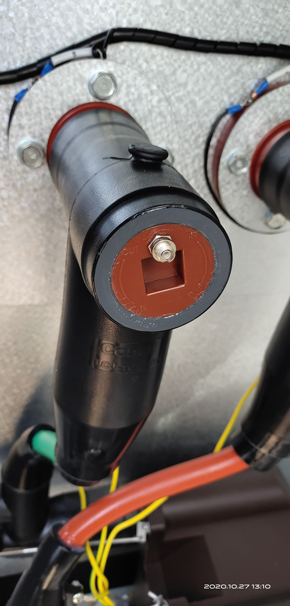
Cable terminations (also called cable heads or cable joints) are critical connection points where underground or overhead power cables interface with electrical equipment such as transformers, switchgear, or overhead lines. These terminations manage the transition from shielded cable construction to exposed conductors while maintaining electrical insulation integrity.
In high-voltage cable systems operating at 10kV, 35kV, 110kV, 220kV and above, terminations experience concentrated electrical stress and heat generation. The connection interface creates resistance that converts electrical current into thermal energy. Temperature monitoring provides the earliest indication of developing problems including poor crimping, insulation degradation, moisture ingress, or overload conditions.
Modern cable termination designs include cold-shrink types (pre-expanded rubber), heat-shrink varieties (thermoplastic materials requiring heat application), and pre-molded terminations (factory-assembled components). Despite design improvements, terminations remain the weakest link—accounting for 60-70% of cable system failures according to IEEE and CIGRE reliability studies.
2. Where Are Cable Temperature Monitoring Systems Deployed?
Electrical substation applications represent the largest deployment area for cable termination monitoring systems. Transmission and distribution substations operate thousands of cable terminations connecting underground feeders to transformer banks, circuit breakers, and bus systems. A single substation may house 50-200 monitored termination points across multiple voltage levels.
Major Application Sectors
Utility Substations and Switchyards
Electric utilities deploy comprehensive monitoring across 138kV, 230kV, and 345kV cable terminations at major switching stations. These critical nodes require 99.9%+ reliability to maintain grid stability. Temperature monitoring enables predictive maintenance during planned outages rather than emergency repairs during storms or peak demand.
Data Center Power Distribution
Modern hyperscale data centers demand extreme uptime—99.995% or better. Medium-voltage cable systems (typically 13.8kV or 34.5kV) distribute power from utility feeds to facility transformers. Continuous temperature monitoring of all cable terminations ensures early fault detection before service disruption.
Industrial Facilities
Manufacturing plants, chemical facilities, and processing operations rely on uninterrupted power. Cable monitoring systems track termination health on critical feeders supplying production equipment. Unexpected outages cost $50,000-$500,000 per hour in lost production and equipment damage.
Rail Transit Power Systems
Metro systems, light rail networks, and high-speed rail utilize extensive underground cable networks. Traction power substations operate hundreds of cable terminations under continuous heavy loading. Temperature monitoring prevents service interruptions affecting thousands of daily passengers.
Wind and Solar Power Plants
Renewable energy installations employ medium-voltage cable systems collecting power from distributed generation sources. Cable terminations at collector substations experience variable loading patterns requiring thermal monitoring to prevent failures during peak generation periods.
3. Why Is Temperature Monitoring Critical for Cable System Reliability?

Economic impact drives investment in cable termination monitoring. Unplanned outages at critical substations cost utilities $1-5 million per event including emergency repairs, replacement equipment, regulatory penalties, and customer compensation. Industrial facilities face production losses of $100,000-$1,000,000 per outage hour.
Thermal Degradation Mechanisms
Electrical insulation materials—cross-linked polyethylene (XLPE), ethylene propylene rubber (EPR), and silicone rubber—experience accelerated aging at elevated temperatures. The Arrhenius relationship governs this degradation: each 10°C temperature rise above rated conditions approximately doubles the aging rate, reducing insulation life by 50%.
A cable termination designed for 30-year service at 90°C maximum hot-spot temperature may fail within 7-10 years if consistently operating at 100°C. This exponential relationship makes continuous temperature monitoring essential for maximizing asset life and avoiding premature replacement costs of $50,000-$200,000 per termination.
Early Warning Capabilities
Temperature monitoring systems detect developing problems hours to weeks before complete failure. A poorly crimped connector gradually increases in resistance, raising temperature 5-15°C above normal over several hours before catastrophic overheating occurs. This advance warning enables controlled shutdown and repair during planned outages rather than emergency response during peak demand.
4. What Are the Most Common Cable Termination Failure Modes?

Comprehensive failure analysis across thousands of cable termination incidents reveals consistent patterns:
Connection Interface Failures (45-50%)
- Inadequate crimping pressure creates high-resistance connections generating excessive heat
- Conductor oxidation increases contact resistance over time, accelerating temperature rise
- Thermal cycling causes expansion/contraction loosening mechanical connections
- Improper lug selection or mixed metals create galvanic corrosion and resistance increase
Insulation System Degradation (30-35%)
- Moisture ingress from seal failures enables partial discharge and dielectric breakdown
- Installation defects including voids, contamination, or stress concentrations
- Thermal aging from sustained overload or cooling system inadequacy
- Tracking and treeing in polymeric insulation under electrical stress
Mechanical and Environmental Issues (15-20%)
- Stress cone misalignment creating field concentration points
- External contamination reducing surface insulation resistance
- Physical damage from wildlife, excavation, or vehicle impact
- Vibration-induced wear in terminations near rotating equipment
5. Why Do Cable Terminations Experience Temperature Abnormalities?
Root cause analysis identifies specific mechanisms triggering thermal excursions in cable termination systems:
Installation Quality Deficiencies
Field installation errors represent 40-50% of temperature-related problems. Insufficient conductor cleaning before crimping leaves oxidation layers increasing contact resistance. Under-crimping applies inadequate compression force, while over-crimping damages conductor strands—both conditions elevate operating temperatures 10-30°C above specification.
Load Current Increases
System load growth frequently pushes cable terminations beyond original design capacity. A termination rated for 600A continuous operation experiences temperature rise from 70°C to 95°C when loaded at 750A (125% rating). Temperature increases as the square of current—a 25% current rise produces 56% higher heat generation.
Environmental Factors
Ambient temperature variations significantly impact termination thermal performance. Summer temperatures elevating ambient conditions from 25°C to 40°C reduce available thermal margin by 15°C. Poor ventilation in enclosed switchgear or underground vaults exacerbates heating, potentially raising steady-state temperatures 20-30°C above open-air installations.
Aging and Degradation
Connection resistance gradually increases over 10-20 year service periods due to oxidation, corrosion, and mechanical relaxation. A termination exhibiting 10μΩ initial contact resistance may reach 50-100μΩ after 15 years, increasing power dissipation by 5-10x and raising temperatures 15-25°C.
6. How Do Temperature Monitoring Technologies Compare?

| Technology | Electrical Isolation | EMI Immunity | Accuracy | Lifespan | Cable Application Suitability |
|---|---|---|---|---|---|
| Fluorescent Fiber Optic | Complete (>100kV) | Total Immunity | ±0.5-1°C | 20+ years | Excellent |
| Wireless RF Sensors | Good | Moderate | ±1-2°C | 5-8 years (battery) | Good |
| Fiber Bragg Grating | Good | Good | ±1-2°C | 15+ years | Moderate |
| GaAs Fiber Optic | Good | Good | ±2-3°C | 10-15 years | Moderate |
| Platinum RTD (PT100) | Requires barriers | Poor | ±0.3-0.5°C | 10-15 years | Limited |
| Infrared Thermal Imaging | Complete | Not affected | ±2-5°C | N/A (periodic) | Limited (manual) |
Technology Selection Criteria
Wireless temperature sensors offer installation convenience but face limitations in high-voltage environments. Battery life of 5-8 years requires periodic replacement during service outages. Radio frequency transmission can experience interference in metal-enclosed switchgear, and high-voltage fields may affect electronics reliability.
Fiber Bragg Grating (FBG) sensors utilize wavelength-encoded measurement enabling multiple sensors on one fiber. However, FBG interrogators cost 2-3x more than fluorescent systems. Mechanical strain from vibration cross-couples with temperature measurement, requiring careful installation. Long-term wavelength stability concerns exist in certain environments.
Platinum RTD sensors provide excellent accuracy but require electrical isolation barriers rated for cable operating voltages. Susceptibility to electromagnetic interference in substation environments necessitates extensive shielding and filtering. Moisture ingress into connection terminals causes measurement errors and corrosion failures.
7. Why Are Fluorescent Fiber Optic Sensors the Optimal Choice?
Fluorescent fiber optic temperature sensors address the unique challenges of high-voltage cable termination monitoring through fundamental measurement principles and system architecture advantages.
Measurement Principle
The sensor probe contains rare-earth phosphor material that fluoresces when excited by LED light transmitted through the optical fiber. Temperature changes the fluorescent decay time from microseconds to milliseconds following excitation pulse termination. The fiber optic transmitter measures this decay time using precision electronics, converting it to calibrated temperature with ±0.5-1°C accuracy.
Exceptional High-Voltage Isolation
Pure silica glass optical fiber provides inherent dielectric isolation exceeding 100kV between the sensor probe (at cable potential) and transmitter electronics (at ground potential). No electrical path exists—eliminating ground loops, safety hazards, and common-mode interference. This is critical where cable terminations operate at 10kV-220kV with transient overvoltages reaching 500kV during switching or lightning events.
Complete EMI Immunity
Optical signal transmission is fundamentally immune to electromagnetic fields. Substation environments generate severe EMI from high-current switching, circuit breaker operations, and transformer energization. Fluorescent fiber optic sensors operate without degradation in these extreme conditions—no shielding, grounding, or filtering required.
Moisture and Chemical Resistance
Cable termination environments experience condensation, humidity, and occasional seal failures introducing moisture. Properly sealed fiber optic sensors are completely immune to moisture-related failures plaguing electrical sensors. Silica fiber is chemically inert to oils, solvents, and cleaning compounds encountered during maintenance.
Dedicated Fiber Architecture
Unlike multiplexed systems, fluorescent fiber optic monitoring uses one dedicated fiber optic cable per sensor probe measuring one specific temperature point. This provides maximum reliability—one fiber failure affects only one measurement, not an entire sensing array. No wavelength crosstalk or multiplexing complexity exists.
Long-Term Calibration Stability
Fluorescent decay time measurement exhibits exceptional stability over 20+ years without calibration drift. The measurement principle is fundamentally stable, determined by quantum mechanical processes that do not degrade. This contrasts with electrical sensors requiring periodic recalibration and replacement.
Customizable Transmitter Modules
Fiber optic temperature transmitters are available in modular configurations from 1 to 64 channels. Each channel connects to one dedicated sensor via one fiber cable. Systems configure precisely for application requirements—16 channels for one substation bay, 48 channels for complete facility coverage. Communication interfaces include Modbus RTU/TCP, DNP3, IEC 61850, and analog outputs for seamless integration.
8. How Should Cable Monitoring Systems Be Configured?
Effective cable termination monitoring requires strategic sensor placement and appropriate system architecture:
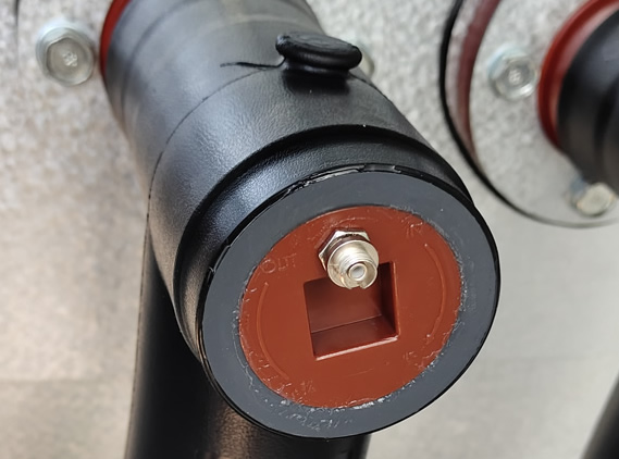
Critical Measurement Locations
| Termination Component | Sensor Location | Sensors Per Termination |
|---|---|---|
| Conductor Connector | Crimped lug barrel surface | 1 sensor |
| Stress Cone Interface | Cable insulation shield termination point | 1 sensor |
| Insulation Surface | Outer termination housing near stress cone | 1 sensor |
| Ground Connection | Cable shield ground lug (optional) | 1 sensor (if critical) |
Typical System Configurations
Substation Bay Monitoring (16-32 channels)
A typical 138kV substation bay with 2-3 cable feeders requires monitoring 6-12 terminations (both ends of each cable). With 2 sensors per termination, this demands 12-24 measurement points. A 32-channel fiber optic transmitter provides complete coverage with expansion capacity.
Data Center Distribution (48-64 channels)
Modern data centers operate 10-20 medium-voltage feeders, each with 2-4 terminations. Comprehensive monitoring of 40-60 termination points requires 64-channel systems with redundant monitoring of critical connections.
Industrial Facility (8-16 channels)
Manufacturing plants typically monitor 4-8 critical incoming feeders and essential distribution circuits. Systems with 8-16 channels cover highest-priority terminations where failures cause maximum production impact.
9. How Do You Install Cable Termination Temperature Sensors?
Installation procedures for fiber optic temperature monitoring systems follow simplified workflows minimizing outage duration:
| Installation Phase | Key Steps | Duration |
|---|---|---|
| Pre-Installation Planning | • Identify critical termination locations • Plan fiber routing paths • Coordinate outage scheduling • Prepare installation materials |
1-2 days |
| Sensor Mounting | • De-energize and ground cables • Clean termination surfaces thoroughly • Attach sensor probes with thermal adhesive • Verify secure mechanical attachment |
15-20 min per sensor |
| Fiber Cable Routing | • Route optical fibers through cable trays • Install protective conduit where required • Maintain minimum bend radius (25mm typical) • Label each fiber at both ends |
2-4 hours |
| Transmitter Connection | • Mount transmitter in control cabinet • Terminate fibers at transmitter connectors • Connect power supply and communications • Configure channel assignments |
2-3 hours |
| System Commissioning | • Verify all channels display valid temperatures • Set alarm thresholds and parameters • Integrate with SCADA/control system • Document configuration and baselines |
2-4 hours |
Installation Best Practices
Surface preparation is critical for sensor adhesion and accurate thermal coupling. Clean termination surfaces with isopropyl alcohol removing all oil, dust, and oxidation. High-temperature thermal adhesive rated for 150°C+ ensures long-term sensor attachment through thermal cycling.
Fiber protection in harsh environments requires armored fiber cables or protective conduit. Maintain minimum bend radius specifications (typically 25mm for standard fiber) to prevent optical signal attenuation. Clearly label each fiber at termination and transmitter ends for maintenance traceability.
10. How Are Temperature Data Applied for Fault Prevention?
Real-time monitoring enables multiple operational improvements:
Continuous Condition Assessment
Operators view real-time temperatures for all monitored cable terminations on SCADA displays. Trend visualization shows temperature evolution during load changes, enabling correlation between power flow and thermal response. Automated alarms trigger when temperatures exceed warning thresholds (typically 70-75°C) or critical limits (80-85°C).
Phase Balance Analysis
Three-phase systems should exhibit similar temperatures across all phases under balanced loading. Temperature differences exceeding 5-10°C between phases indicate unbalanced loading, poor connections on specific phases, or developing insulation problems. This analysis identifies issues before single-phase failure occurs.
Predictive Maintenance Triggering
Gradual temperature increases over weeks to months indicate progressive degradation—connector oxidation, insulation aging, or cooling inadequacy. Trending analysis detects 2-5°C per month temperature rises, enabling planned maintenance during scheduled outages rather than emergency repairs.
Load Capacity Verification
Temperature monitoring validates available thermal margin for load increases. If maximum observed temperature during peak loading is 65°C with an 85°C limit, 20°C margin exists for potential load growth without equipment upgrades.
11. What Results Have Real Installations Achieved?
Case Study 1: 138kV Substation Connector Failure Prevention
Location: Major utility substation, northeastern United States
Problem: Unexpected high-temperature alarm on Phase B cable termination during summer peak loading, reaching 88°C
Action Taken: Controlled load transfer to alternate feeders and planned shutdown within 4 hours. Inspection revealed severely oxidized connector with 10x normal resistance—caught before complete failure that would have required emergency repair during peak demand period.
Result: Avoided $1.2 million in estimated emergency repair costs and customer outage penalties. Repair completed during planned 8-hour outage versus potential 48-72 hour emergency restoration.
Case Study 2: Data Center Thermal Monitoring
Facility: 20MW hyperscale data center, western United States
Implementation: 64-channel fiber optic monitoring system covering all 32 medium-voltage cable terminations (13.8kV) with 2 sensors per termination
Benefits: Detected developing hot-spot on one utility service entrance termination showing 12°C temperature rise over 3 weeks. Investigation identified installation defect (inadequate crimping) corrected during planned maintenance. System has operated 5+ years with zero termination failures versus industry average of 1-2 failures per 100 terminations annually.
Case Study 3: Transit System Reliability Improvement
Application: Metro rail traction power substations, major transit authority
Challenge: Frequent cable termination failures on 34.5kV feeders causing service disruptions affecting 50,000+ daily riders
Solution: Installed comprehensive monitoring across 12 traction substations, 144 total terminations. Temperature trending identified chronic overheating at 8 locations during peak service periods, enabling proactive connector replacement and ventilation improvements.
Outcome: Cable-related service interruptions reduced by 75% over 3-year period. System availability improved from 97.8% to 99.4%, meeting transit authority reliability targets.
12. Frequently Asked Questions
Q1: What is the normal operating temperature for cable terminations?
A: Well-designed cable terminations under normal loading typically operate at 50-70°C conductor temperature. Maximum continuous ratings are usually 90°C for XLPE insulation and 105°C for EPR insulation. Warning alarms should trigger at 70-75°C, with critical alarms at 80-85°C to provide intervention time before insulation damage occurs.
Q2: How many cable terminations can one monitoring system handle?
A: Fiber optic transmitters are available in configurations from 1 to 64 channels. Each channel monitors one dedicated sensor location. A 32-channel system can monitor 16 cable terminations with 2 sensors each, or 32 terminations with single-point monitoring. Systems are modular and expandable—additional transmitters add capacity as monitoring needs grow.
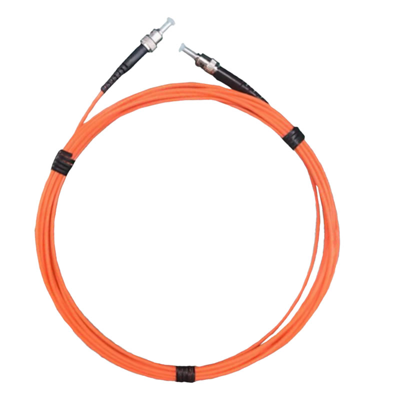
Q3: How are fiber optic sensors attached to cable terminations?
A: Sensor probes attach using high-temperature thermal adhesive rated for 150-200°C continuous operation. Proper surface cleaning (isopropyl alcohol) ensures adhesion. The small probe size (2-3mm diameter) enables mounting on connector lugs, stress cone surfaces, or termination housings. Mechanical clips provide additional security in high-vibration environments.
Q4: Can the system integrate with existing substation automation?
A: Yes, fiber optic transmitters support standard industrial protocols including Modbus RTU/TCP (most common), DNP3 (utility standard), IEC 61850 (substation automation), and analog outputs (4-20mA). Direct integration into SCADA systems, DCS platforms, or protective relay schemes enables automated alarming and control actions.
Q5: Does installation require cable de-energization?
A: Yes, safe sensor installation on cable terminations requires de-energization and grounding per utility safety procedures. However, installation during planned maintenance outages takes only 15-20 minutes per sensor. Fiber routing to transmitters can occur with cables energized since optical fiber provides complete electrical isolation.
Q6: What happens if an optical fiber is damaged?
A: The dedicated fiber architecture means one fiber failure affects only that single measurement point—other channels continue normal operation. The fiber optic transmitter detects fiber breaks and generates fault alarms. Damaged fibers are easily replaced by installing new fiber cable from sensor to transmitter without affecting the sensor probe itself.
Q7: How do you distinguish normal load-related heating from abnormal temperature rise?
A: Normal load increases produce proportional temperature rises across all three phases, correlating with measured current. Abnormal conditions show disproportionate temperature on one phase, continued temperature rise despite stable load, or temperature increases during constant loading. Advanced systems maintain load-temperature correlation models triggering alarms when measured values deviate from expected patterns.
Q8: What is the expected system lifespan?
A: Fluorescent fiber optic sensors demonstrate 20+ year operational life with zero calibration drift. Optical fiber and sensor probes have no wearing parts or consumables. Transmitter electronics typically carry 10-15 year design life with extended operation through component replacement. Total system life expectancy exceeds 20 years—matching or exceeding cable termination service life.
Q9: Can outdoor cable terminations be monitored?
A: Yes, fiber optic sensors operate reliably in outdoor environments. UV-resistant fiber jackets protect against sunlight exposure. Sensor probes seal against moisture ingress. Temperature range specifications (-40°C to +200°C) exceed environmental extremes. Transmitters mount in climate-controlled buildings with fiber cables routing through underground conduit or aerial cable trays.
Q10: How does cost compare to traditional monitoring approaches?
A: Initial equipment costs for fluorescent fiber optic systems run 20-30% higher than wireless sensors or RTD systems. However, total cost of ownership is 30-40% lower over 15-20 year life cycles due to elimination of battery replacements, recalibration requirements, and failure-related costs. Single prevented outage typically recovers entire system investment.
Get Your Customized Cable Monitoring Solution
Professional Engineering Support Includes:
- Complimentary application consultation and thermal risk assessment for your specific installation
- Customized temperature monitoring system design with optimal sensor placement recommendations
- Detailed technical specifications for fiber optic sensors, transmitters, and integration requirements
- Complete system proposal with equipment pricing and installation timeline
- Factory testing and calibration verification before shipment
- On-site installation supervision and system commissioning services
- Comprehensive operator and maintenance personnel training
- Long-term technical support and predictive maintenance consulting
Contact Our Cable Monitoring Specialists Today:
Protect your critical power infrastructure and prevent costly cable failures with proven fluorescent fiber optic temperature monitoring technology.
Our engineering team will work with you to develop a monitoring solution precisely matched to your facility’s voltage levels, termination types, environmental conditions, and integration requirements.
Serving electric utilities, industrial facilities, data centers, transit systems, and renewable energy installations across North America with specialized expertise in high-voltage cable termination monitoring from 10kV through 345kV applications.
Request your free consultation and detailed quotation today.

Fiber optic temperature sensor, Intelligent monitoring system, Distributed fiber optic manufacturer in China
 |
 |
 |