 INNO fibre optic temperature sensors ,temperature monitoring systems.
- Temperature monitoring is critical for transformer safety – Real-time monitoring of winding and oil temperatures through various sensor technologies prevents overheating damage and extends equipment lifespan
- PT100 sensors offer proven reliability – Platinum resistance temperature detectors provide high accuracy, long-term stability, and wide temperature range for both dry-type and oil-filled transformers
- Fluorescent fiber optic sensors excel in high-voltage environments – Immune to electromagnetic interference, intrinsically safe, and capable of multi-point measurement without electrical connections
- Multiple sensor types serve different applications – PT100, fluorescent fiber optic, infrared, and wireless sensors each offer unique advantages for specific monitoring requirements
- Understanding temperature failure causes is essential – Overloading, cooling system failures, insulation degradation, and poor connections are primary causes of transformer temperature problems
- Proper sensor selection impacts reliability – Choosing the right temperature monitoring solution based on transformer type, voltage class, and environmental conditions ensures accurate and dependable operation
- Leading manufacturers provide tested solutions – Global suppliers offer certified temperature monitoring systems that meet international standards and industry requirements
What Is a Transformer Temperature Sensor?
A transformer temperature sensor is a critical monitoring device designed to measure and track the thermal conditions within electrical transformers. These sensors continuously monitor the temperature of key components, including transformer windings, insulating oil, and core materials, providing essential data for safe operation and preventing catastrophic failures.
Temperature sensors serve as the first line of defense against thermal damage in power distribution systems. When transformer components exceed their rated temperature limits, insulation materials degrade rapidly, potentially leading to short circuits, fires, or complete equipment failure. Modern temperature monitoring systems integrate multiple sensor types to provide comprehensive thermal protection across all critical zones.
Primary Functions of Temperature Sensors
The fundamental role of transformer temperature monitoring devices extends beyond simple measurement. These sensors enable operators to detect abnormal heating patterns before they cause permanent damage, trigger automatic cooling systems when temperatures rise, provide data for load management decisions, and generate historical records for predictive maintenance programs.
In industrial and utility applications, temperature sensing equipment connects to supervisory control and data acquisition (SCADA) systems, allowing remote monitoring of entire transformer fleets. This connectivity enables rapid response to thermal events and supports data-driven maintenance strategies that maximize equipment reliability while minimizing operational costs.
What Is a PT100 Sensor for Dry-Type Transformers?
A PT100 sensor is a platinum resistance temperature detector (RTD) specifically designed for accurate temperature measurement in dry-type transformers. The designation “PT100” indicates a platinum element with a resistance of 100 ohms at 0°C, offering exceptional accuracy and stability across a wide temperature range from -200°C to +850°C.
For dry-type transformer applications, PT100 sensors provide several distinct advantages over other temperature measurement technologies. These sensors maintain excellent linearity throughout their operating range, deliver repeatable measurements over many years of service, resist degradation from mechanical vibration and electrical noise, and comply with international standards including IEC 60751.
PT100 Construction and Installation
In dry-type transformers, PT100 resistance temperature detectors are typically embedded directly into the winding assemblies during manufacturing or installed in pockets that make thermal contact with critical components. The sensor element consists of a fine platinum wire wound on a ceramic or glass core, encapsulated in a protective stainless steel sheath that shields it from environmental contaminants while allowing efficient heat transfer.
The winding temperature indicator utilizing PT100 technology connects to a temperature transmitter or controller that converts the resistance signal into a standardized output such as 4-20mA or digital protocols like Modbus or Profibus. This allows seamless integration with building management systems and industrial control networks.
What Are the Main Types of Temperature Sensors for Transformers?

Transformer temperature monitoring relies on four primary sensor technologies, each offering distinct characteristics suited to specific applications and operating environments.
PT100 Resistance Temperature Detectors
PT100 RTD sensors represent the industry standard for transformer temperature measurement due to their superior accuracy (±0.15°C at 0°C), excellent long-term stability, and resistance to electrical interference. These sensors work equally well in both oil-immersed transformers and cast resin transformers, making them the most versatile option for diverse installations.
Fluorescent Fiber Optic Sensors
Fluorescent fiber optic temperature sensors utilize the temperature-dependent decay time of fluorescent materials to measure temperature with exceptional accuracy. Unlike electrical sensors, these devices are completely immune to electromagnetic interference, contain no metallic components that could conduct electricity, and provide galvanic isolation between sensing points and monitoring equipment.
The fiber optic sensing technology excels in high-voltage environments where traditional electrical sensors pose safety risks or suffer from electromagnetic interference that compromises measurement accuracy.
Infrared Temperature Sensors
Infrared thermal sensors measure surface temperatures without physical contact by detecting thermal radiation emitted from transformer components. These non-contact devices prove particularly useful for monitoring external surfaces, hot spot detection during thermal surveys, and temporary measurements during commissioning or troubleshooting.
Wireless Temperature Sensors
Wireless temperature monitoring systems transmit measurement data via radio frequency signals, eliminating the need for signal wiring between sensors and monitoring equipment. These battery-powered or energy-harvesting devices simplify retrofitting existing transformers with enhanced monitoring capabilities and reduce installation costs in distributed monitoring applications.
Comparison Table: PT100 vs Fluorescent Fiber Optic Sensors
| Feature | PT100 Sensors | Fluorescent Fiber Optic Sensors |
|---|---|---|
| Accuracy | ± 1% FS (temperature controller level 0.5, sensor level B) | ±0.5°C to ±1°C |
| EMI Immunity | Good with proper shielding | Complete immunity |
| Intrinsic Safety | Requires barriers in hazardous areas | Inherently safe, no electrical energy |
| Installation Complexity | Moderate, requires wiring | Simple, lightweight fiber cables |
| Long-term Stability | Excellent, proven over decades | Excellent, no drift |
| Temperature Range | -30.0℃~240.0℃ | -40°C to +300°C (typical) |
| Response Time | Fast (seconds) | Very fast (sub-second) |
| Cost | Lower initial cost | Higher initial cost, lower installation |
| Maintenance | Periodic calibration recommended | Minimal, no calibration drift |
How Do You Check Transformer Temperature?
Checking transformer operating temperature involves multiple measurement techniques and monitoring points to ensure comprehensive thermal assessment. Operators employ both continuous monitoring systems and periodic manual inspections to verify that all components operate within safe thermal limits.
Continuous Monitoring Methods
Modern transformers incorporate permanent temperature monitoring instrumentation that provides real-time data on critical thermal parameters. Winding temperature indicators continuously measure the hottest spot in transformer coils, while oil temperature gauges track the thermal condition of insulating fluid in oil-filled units. These instruments connect to alarm systems that alert operators when temperatures approach or exceed preset thresholds.
For power transformers in substations, temperature data typically feeds into digital protection relays and SCADA systems, enabling automated responses such as activating forced cooling, reducing load, or tripping the transformer offline if dangerous temperatures persist.
Periodic Inspection Techniques
Manual temperature checks using infrared thermography provide valuable supplementary data, particularly for detecting localized hot spots on bushings, tap changers, and external connections. Thermographic surveys should be conducted during periods of high load when temperature differences are most pronounced, allowing operators to identify developing problems before they cause failures.
Temperature Monitoring Best Practices
Effective temperature verification requires establishing baseline measurements during initial commissioning, comparing current readings against historical trends to identify gradual changes, correlating temperature data with load levels and ambient conditions, investigating any sudden temperature increases regardless of absolute values, and documenting all temperature readings for trend analysis and regulatory compliance.
How Does a Transformer Temperature Sensor Work?
The operating principle of temperature sensors varies based on the sensing technology employed, but all types convert thermal energy into measurable signals that monitoring systems can interpret and act upon.
Resistance-Based Sensing (PT100/RTD)
Resistance temperature detectors exploit the predictable relationship between temperature and electrical resistance in pure metals. For platinum RTDs like PT100 sensors, resistance increases nearly linearly with temperature according to the Callendar-Van Dusen equation. A precision measuring circuit passes a small, constant current through the platinum element and measures the resulting voltage drop, which directly correlates to temperature.
The RTD measurement circuit typically uses a four-wire configuration to eliminate errors from lead wire resistance, ensuring that only the sensor element’s resistance affects the measurement. This configuration provides accuracy better than 0.1% of reading across the full temperature span.
Fluorescent Decay Time Sensing
Fluorescent fiber optic sensors employ a fundamentally different principle based on the temperature-dependent fluorescence decay time of rare-earth phosphors. A brief pulse of excitation light travels down the optical fiber to the sensor probe, where it stimulates fluorescence in the temperature-sensitive material. The intensity of this fluorescence decays exponentially, with the decay time constant varying predictably with temperature.
The monitoring equipment measures this decay time with high precision, converting it to a temperature reading that is inherently immune to light source variations, fiber bending losses, or connector degradation. This optical temperature measurement method provides exceptional stability and reliability in harsh electromagnetic environments.
Infrared Radiation Sensing
Non-contact infrared sensors detect thermal radiation emitted by all objects above absolute zero. The intensity and spectral distribution of this radiation depend on the object’s temperature and emissivity. By focusing infrared energy onto a detector element, these sensors can determine surface temperature from a distance, making them ideal for energized components that cannot be safely accessed during operation.
What Is a Transformer Winding Temperature Sensor?
A winding temperature sensor specifically monitors the thermal condition of transformer coil assemblies, which typically operate at higher temperatures than surrounding oil or ambient air. These specialized sensors must withstand the electrical, mechanical, and thermal stresses present within active windings while providing accurate, reliable temperature data throughout the transformer’s service life.
Direct Winding Sensors
Embedded winding sensors are installed directly into transformer coils during manufacturing, providing the most accurate measurement of actual conductor temperature. For dry-type transformers, PT100 sensors are commonly embedded between winding layers at calculated hot spot locations. In oil-filled transformers, fiber optic probes may be positioned in contact with inner winding surfaces where temperatures peak during heavy load conditions.
The placement of hot spot temperature sensors requires careful thermal analysis to identify locations where peak temperatures occur under various loading scenarios. Manufacturers typically install multiple sensors at different radial and axial positions within large power transformers to ensure comprehensive thermal monitoring.
Indirect Temperature Measurement
Many transformers use winding temperature indicators (WTI) that infer coil temperature by combining top oil temperature measurements with a thermal model of the winding-to-oil temperature gradient. A heater element powered proportionally to load current warms the sensing element to simulate winding temperature rise above the oil temperature.
Winding Temperature Monitoring Applications
Accurate winding temperature data enables multiple protective and operational functions including overload protection that prevents insulation damage, dynamic rating calculations that maximize utilization during cool weather, cooling system control that optimizes energy consumption, and predictive maintenance that extends transformer life by avoiding thermal aging.
How Does a Transformer Oil Temperature Gauge Function?
The transformer oil temperature gauge measures the thermal condition of insulating oil in liquid-filled transformers, providing critical data about the overall thermal state of the unit. Since oil temperature directly affects cooling efficiency and insulation performance, continuous monitoring prevents dangerous operating conditions.
Top Oil Temperature Measurement
Top oil temperature indicators measure the warmest oil in the transformer, which rises to the top of the tank due to natural convection. A sensor probe extends into the oil at the highest point of the main tank, where temperature peaks during operation. This measurement serves multiple purposes including alarm and trip functions, cooling system activation, thermal aging calculations, and load management decisions.
Modern digital oil temperature monitors provide not only local display but also analog or digital outputs for remote monitoring and control systems. Advanced units incorporate data logging to record temperature profiles over time, supporting forensic analysis after equipment failures.
Temperature Sensing Technologies for Oil
Various sensor types serve oil temperature measurement applications. PT100 RTDs offer excellent accuracy and stability for both top oil and bottom oil measurements, thermocouples provide economical solutions for less critical monitoring points, and fiber optic sensors enable interference-free measurements in locations with severe electromagnetic fields.
Oil Temperature Gradient Monitoring
Large power transformers may incorporate multiple oil temperature sensors at different heights within the tank to monitor thermal stratification. Excessive temperature gradients can indicate cooling system problems, blocked oil passages, or abnormal internal heating that requires investigation.
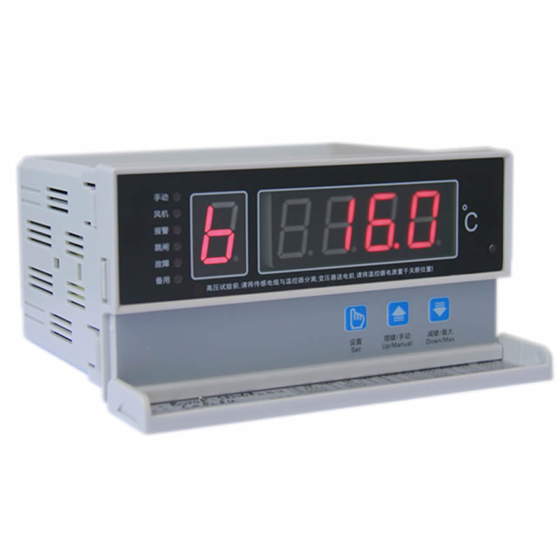
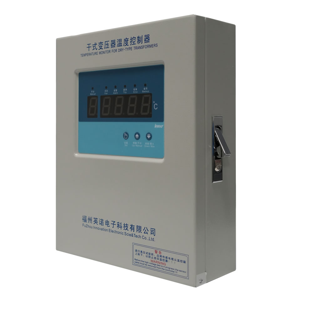
What Does a Transformer Temperature Controller Do?
A transformer temperature controller integrates temperature sensor inputs with control logic to protect equipment and optimize cooling system operation. These intelligent devices form the brain of transformer thermal management systems, making automated decisions that maintain safe operating conditions while maximizing efficiency.
Core Functions
Temperature control systems continuously process inputs from winding sensors, oil gauges, and ambient temperature detectors to perform several critical functions. They activate cooling fans or pumps when temperatures exceed start thresholds, trigger alarms when preset warning levels are reached, initiate automatic load reduction or transformer shutdown at critical temperatures, and record temperature data for trend analysis and regulatory reporting.
Advanced Controller Features
Modern digital temperature controllers incorporate sophisticated capabilities beyond simple threshold monitoring. Adaptive cooling control algorithms optimize fan operation based on load patterns and ambient conditions to minimize energy consumption, thermal modeling calculates remaining time to critical temperature at current load levels, communication interfaces enable integration with substation automation and SCADA systems, and self-diagnostic functions verify sensor operation and detect measurement anomalies.
Cooling System Management
Forced cooling control represents a primary function of temperature controllers in large transformers. By staging multiple cooling banks based on temperature trends rather than fixed setpoints, intelligent controllers maintain optimal thermal margins while avoiding excessive energy consumption and reducing mechanical wear on cooling equipment.
What Is the Operating Temperature Range for Transformer Windings?
The permissible temperature range for transformer windings depends on the insulation class and design standards applicable to the specific transformer type. Understanding these limits is essential for proper operation and maintenance of electrical distribution equipment.
Standard Temperature Limits
For oil-immersed transformers using conventional insulation systems, IEEE and IEC standards establish temperature limits based on insulation class. The average winding temperature should not exceed 65°C rise above ambient under rated load for Class A insulation (105°C total), while hot spot temperature limits typically restrict peak winding temperatures to 110°C rise above ambient (140°C total) for normal life expectancy.
Dry-type transformers employ different insulation systems with higher temperature capabilities. Class F insulation allows average winding temperature rise of 100°C above ambient (130°C rise for hot spot), while Class H systems permit 115°C average rise (150°C hot spot rise), enabling more compact designs and higher power density.
Temperature and Insulation Life
The relationship between operating temperature and insulation aging follows the Arrhenius equation, where reaction rates double for every 8-10°C temperature increase. This means that continuous operation at temperatures exceeding design limits significantly accelerates insulation degradation, potentially reducing transformer life from decades to years.
Loading Beyond Nameplate Rating
Transformers can operate above nameplate capacity if temperatures remain within acceptable limits. Emergency loading guides published by IEEE and IEC define permissible overloads based on pre-load temperature, duration of overload, and acceptable loss of life. Temperature monitoring becomes critical during these operating conditions to prevent exceeding thermal limits that cause permanent damage.
How Do You Measure Transformer Winding Temperature?
Measuring transformer winding temperature accurately presents unique challenges because the hottest points are buried deep within the coil assembly, inaccessible during normal operation. Engineers employ several proven techniques to obtain reliable thermal data for these critical components.
Direct Measurement Methods
Embedded temperature sensors provide the most accurate winding temperature data by placing sensing elements in direct thermal contact with conductors. During transformer manufacturing, PT100 sensors or fiber optic probes are positioned at calculated hot spot locations between winding layers. These sensors remain in place throughout the transformer’s operational life, continuously monitoring actual conductor temperatures.
For cast resin transformers, sensors are embedded in the epoxy encapsulation during the casting process, creating a permanent thermal monitoring system. The number and location of sensors depends on transformer size and criticality, with large units incorporating multiple sensors to map temperature distribution throughout the winding structure.
Indirect Calculation Methods
Many transformers use thermal imaging techniques that combine top oil temperature with calculated winding-to-oil gradient. The winding temperature indicator applies a correction factor based on load current to estimate hot spot temperature. While less accurate than direct measurement, this approach provides reliable monitoring at lower cost for medium-sized transformers.
Thermal Modeling
Advanced thermal analysis software can predict winding temperature distribution based on load current, oil temperatures, cooling system status, and ambient conditions. These models, validated against measured data during factory testing, enable real-time hot spot temperature estimation even in transformers without embedded sensors.
What Are Fiber Optic Temperature Sensors for Transformers?
Fiber optic temperature sensors represent advanced monitoring technology specifically designed to overcome the limitations of conventional electrical sensors in high-voltage transformer applications. These optical sensing systems eliminate electrical connections between sensing points and monitoring equipment, providing inherent safety and immunity to electromagnetic interference.
Fluorescent Fiber Optic Technology
The most common fiber optic sensing system for transformers uses fluorescent decay time measurement. A small probe containing rare-earth phosphor material attaches to the fiber optic cable and is positioned at the measurement point within the transformer. Ultraviolet light pulses travel down the fiber to excite the phosphor, which emits visible light with a decay time that varies predictably with temperature.
This optical temperature measurement technique offers several critical advantages for transformer applications including complete electrical isolation between sensor and electronics, immunity to electromagnetic and radio frequency interference, intrinsically safe operation in hazardous locations, and no metallic components that could become energized or create ground loops.
Installation in High-Voltage Equipment
Fiber optic probes can be installed in locations where electrical sensors would pose safety risks or suffer from interference. The non-conductive glass fiber passes through high-voltage barriers without requiring insulated bushings or isolation amplifiers. This simplifies installation and eliminates potential failure modes associated with electrical sensor systems.
Multi-Point Monitoring
A single fiber optic monitoring system can interrogate dozens of sensor points distributed throughout a transformer, providing comprehensive thermal mapping impossible with conventional wiring. This capability proves particularly valuable in large power transformers where understanding temperature distribution helps optimize loading and predict maintenance requirements.
Where Should Temperature Sensors Be Installed?
Strategic placement of temperature monitoring sensors ensures comprehensive thermal protection while optimizing the number of sensors required. Installation locations should capture peak temperatures at critical failure points and provide representative measurements for thermal management decisions.
Winding Sensor Locations
For transformer windings, sensors must be positioned at calculated hot spot locations where maximum temperatures occur under load. In layer-type windings, hot spots typically appear in the upper portion of inner layers where heat dissipation is poorest. Disc-type windings concentrate heat near the core in lower discs. Thermal analysis during design identifies optimal sensor positions, typically resulting in placement at the radial center of windings, in the upper third of the winding height, and at locations with restricted oil flow.
Oil Temperature Measurement Points
Oil temperature sensors should monitor both top oil where maximum temperatures occur and bottom oil to assess temperature gradient. Large transformers benefit from multiple oil sensors at different heights to detect stratification or circulation problems. Top oil sensors extend into the oil pocket at the highest point of the main tank, bottom oil sensors mount near the cooler inlet or tank bottom, and additional sensors may monitor oil entering and leaving cooling equipment.
Ambient and Cooling System Monitoring
Comprehensive thermal monitoring systems incorporate ambient temperature measurement for dynamic rating calculations and cooling system sensors to verify proper operation. Monitoring air temperature at cooler inlets helps optimize fan operation, while oil temperature before and after coolers confirms heat exchanger effectiveness.
What Causes Transformer Temperature Failures?
Understanding the root causes of transformer overheating enables proactive maintenance and operational strategies that prevent costly failures. Temperature-related problems typically arise from several distinct mechanisms, often working in combination to create dangerous thermal conditions.
Overloading and Excessive Current
Sustained overload conditions represent the most common cause of transformer temperature failures. When load current exceeds design limits, I²R losses in windings increase exponentially, generating more heat than cooling systems can dissipate. This situation commonly occurs due to load growth exceeding transformer capacity, failure of parallel transformers forcing load transfer, incorrect transformer sizing during installation, or temporary emergency conditions that persist longer than planned.
Even brief overloads can cause cumulative damage if they occur frequently. The thermal cycling from repeated overheating weakens insulation through expansion and contraction, eventually leading to dielectric failure even if peak temperatures never reach critical limits.
Cooling System Failures
Inadequate heat dissipation causes temperatures to rise even at normal load levels. Cooling system problems that trigger temperature failures include radiator or cooler blockage by dirt or debris, fan or pump motor failures, loss of cooling medium (oil leaks in oil-filled units), incorrect cooling equipment settings or control failures, and ambient temperature exceeding design assumptions.
In forced-air cooled transformers, a single fan failure may seem minor but can create localized hot spots if the affected area loses adequate cooling. Monitoring systems should detect cooling equipment problems by identifying abnormal temperature rises relative to load.
Insulation System Degradation
Insulation deterioration creates a vicious cycle where initial aging increases electrical losses, generating additional heat that accelerates further degradation. Common insulation problems leading to temperature failures include moisture contamination reducing dielectric strength and thermal performance, partial discharge activity creating localized heating, chemical breakdown of insulation materials, and contamination by particles or conductive materials.
Poor Electrical Connections
Loose or corroded connections create high-resistance joints that generate excessive heat. These hot spots typically occur at bushing terminals, tap changer contacts, internal lead connections, and grounding system joints. Unlike distributed winding temperature increases, connection problems create intense localized heating that standard sensors may not detect if positioned far from the problem area.
Internal Faults
Incipient faults within transformer windings or core structures produce abnormal heating patterns before developing into catastrophic failures. Turn-to-turn shorts create circulating currents and localized heating, core insulation breakdown causes eddy current losses, and internal arcing generates intense heat in small areas. Detecting these problems requires sensitive monitoring that identifies unusual temperature distributions or unexpected temperature increases at normal load.
What Are Best Practices for Transformer Thermal Management?
Effective thermal management strategies maximize transformer reliability and lifespan while optimizing operational flexibility and efficiency. Implementing proven practices for temperature control reduces failure rates and extends equipment service intervals.
Load Management
Dynamic loading strategies adjust transformer utilization based on real-time thermal conditions rather than fixed nameplate ratings. By continuously monitoring winding and oil temperatures alongside ambient conditions, operators can safely increase loading during cool weather while maintaining appropriate thermal margins. This approach requires accurate temperature measurement, validated thermal models, defined risk tolerance for loss-of-life acceleration, and automated systems that can respond quickly to changing conditions.
Cooling System Optimization
Modern cooling control algorithms minimize energy consumption while maintaining safe temperatures. Rather than running all cooling equipment whenever temperature exceeds a threshold, intelligent systems stage cooling banks based on rate of temperature rise, adjust fan speed to match actual cooling requirements, and shut down excess cooling capacity during light load periods. These strategies can reduce cooling energy consumption by 30-50% compared to simple on-off control.
Preventive Maintenance
Regular thermal system maintenance prevents degradation that leads to temperature failures. Essential maintenance activities include cleaning radiators and coolers to maintain heat transfer efficiency, testing and exercising cooling fans and pumps, verifying temperature sensor accuracy against reference standards, inspecting electrical connections for signs of overheating, and analyzing oil quality to detect contamination or degradation.
Temperature Trending and Analysis
Historical temperature data reveals developing problems before they cause failures. Operators should establish baseline temperature profiles at various load levels, monitor for gradual increases that indicate cooling system degradation, investigate sudden changes in temperature patterns, and correlate temperature behavior with load, ambient conditions, and cooling system operation.
Who Are the Top 10 Transformer Temperature Sensor Manufacturers?
Selecting reliable temperature monitoring equipment from established manufacturers ensures long-term performance and support. The following companies represent industry leaders in transformer thermal protection systems:
1. FJINNO
We are a high-tech enterprise with strong capabilities. Our main products include fluorescent fiber optic temperature measurement systems, oil immersed transformer fiber optic temperature online monitoring systems, environmental management systems, rail transit fiber optic temperature controllers, PHM online monitoring systems, dry-type transformer temperature controllers, etc. Together with universities such as Fuzhou University, we have successfully developed fluorescent fiber optic temperature sensors with independent intellectual property rights, providing overall solutions and application services for temperature, vibration, pressure and other monitoring in comprehensive pipe galleries, oil and gas pipelines, rail transit, power, municipal, nuclear power, new energy, chemical and other fields. In the era of rapid development of the Internet of Things industry, InnoTech will rise to the forefront and become a provider and application service provider of intelligent temperature measurement system overall solutions.
2. WIKA Instruments
WIKA manufactures precision temperature sensors and instrumentation for transformer applications, including PT100 RTDs, thermocouples, and digital temperature transmitters. Their products meet international standards and provide reliable measurements in demanding environments.
3. Siemens
Siemens Energy produces integrated transformer monitoring systems that combine temperature sensors with advanced diagnostics and control capabilities. Their solutions support both new installations and retrofits of existing equipment.
4. ABB
ABB offers comprehensive transformer monitoring products including temperature sensors, controllers, and complete asset management platforms. Their systems enable predictive maintenance and optimal transformer utilization.
5. OMEGA Engineering
OMEGA provides a wide range of temperature sensors suitable for transformer applications, including industrial-grade RTDs, thermocouples, and wireless monitoring systems. Their products serve applications from small distribution transformers to large power units.
6. Neoptix (Luna Innovations)
Neoptix fiber optic sensors excel in high-voltage transformer monitoring where immunity to electromagnetic interference is critical. Their fluorescent decay technology provides accurate, reliable measurements in the most challenging electrical environments.
7. REINHAUSEN (MR)
Maschinenfabrik Reinhausen manufactures transformer monitoring equipment including advanced temperature sensors and controllers designed specifically for power transformer applications. Their products integrate seamlessly with tap changer controls and other transformer accessories.
8. Schweitzer Engineering Laboratories (SEL)
SEL produces digital protection and monitoring systems that incorporate temperature monitoring for comprehensive transformer protection. Their integrated approach combines thermal, electrical, and dissolved gas monitoring.
9. Vaisala
Vaisala offers temperature and humidity monitoring solutions for transformer applications, particularly for dry-type units where ambient conditions significantly affect thermal performance.
10. Keller America
Keller manufactures robust temperature sensors for industrial applications including transformers. Their products emphasize reliability and accuracy in harsh environments.
Frequently Asked Questions
What is the normal operating temperature for a transformer?
Normal transformer operating temperatures vary by type and loading. Oil-filled transformers typically operate with top oil temperatures of 60-80°C and winding hot spots of 90-110°C under full load. Dry-type transformers run hotter, with winding temperatures of 100-150°C depending on insulation class. These temperatures assume standard ambient conditions of 30-40°C.
How often should transformer temperature sensors be calibrated?
Temperature sensor calibration intervals depend on sensor type and application criticality. PT100 sensors in stable installations may require verification only every 5-10 years, while sensors in critical applications should be checked annually. Fiber optic sensors typically require no calibration as they don’t drift over time. Always calibrate after any sensor replacement or repair.
Can I use standard industrial temperature sensors in transformers?
While standard sensors may physically fit, transformer-specific sensors are engineered for the unique electrical, thermal, and environmental conditions inside power equipment. They must withstand high voltage stress, resist insulating oil or resin, tolerate vibration and thermal cycling, and meet safety standards for hazardous locations. Using non-approved sensors risks measurement errors, safety hazards, or premature sensor failure.
What causes false temperature alarms in transformers?
False temperature alarms commonly result from sensor failures, wiring problems, or controller malfunctions rather than actual overheating. Common causes include moisture in sensor connections creating resistance changes, electromagnetic interference affecting sensor signals, calibration drift in aging sensors, and incorrect controller setpoints. Always verify actual transformer temperature through multiple independent measurements before assuming an alarm is false.
How do I choose between PT100 and fiber optic sensors?
Select PT100 sensors for cost-effective monitoring in medium voltage transformers where proven technology and wide vendor support are priorities. Choose fiber optic sensors for high-voltage applications where electromagnetic immunity is essential, in locations where intrinsic safety is required. Consider that fiber optic systems have higher initial costs but may reduce installation expenses in complex applications.
What temperature triggers transformer alarms?
Alarm temperatures vary by transformer type and design but typically include warning alarms at 80-85°C top oil or 110-120°C winding temperature, trip alarms at 90-95°C top oil or 130-140°C winding temperature, and emergency shutdown at temperatures exceeding insulation limits. Settings should account for transformer insulation class, loading category, and risk tolerance. Consult manufacturer specifications and applicable standards when establishing alarm setpoints.
Can transformers recover from overheating?
Transformers can operate normally after brief temperature excursions if peak temperatures and duration remain within emergency loading guidelines. However, each overheating event causes cumulative insulation aging that reduces remaining life. Severe overheating that degrades insulation properties or causes physical damage may permanently compromise the transformer, requiring extensive testing to verify continued fitness for service. Prevention through proper monitoring and load management is always preferable to recovery from thermal damage.
Do I need separate sensors for each winding?
Multi-winding transformers benefit from individual winding monitoring because different voltage levels may have different loading patterns and thermal characteristics. At minimum, monitor the highest-temperature winding, which is typically the low-voltage winding due to higher current and associated losses. Large power transformers often include sensors in all major windings to enable precise thermal management and fault detection.

Fiber optic temperature sensor, Intelligent monitoring system, Distributed fiber optic manufacturer in China
 |
 |
 |