 INNO fibre optic temperature sensors ,temperature monitoring systems.
- EMI-immune temperature sensors deliver accurate, drift-free readings inside electrically noisy environments where thermocouples, RTDs, and wireless probes routinely fail.
- Ignoring electromagnetic immunity can trigger false alarms, protection mis-operation, transformer fires, and unplanned outages that cost utilities millions per incident.
- Typical deployments include power transformers, GIS switchgear, generator stator windings, HVDC converter halls, induction furnaces, MRI and RF ablation equipment.
- Core immunity technologies are fluorescence decay, fiber Bragg grating (FBG), gallium arsenide (GaAs), and Fabry-Pérot interferometry — each with a clear sweet spot.
- For most utility and industrial buyers, a fluorescence-based fiber optic system offers the best balance of cost, accuracy, and dielectric strength.
- This guide reviews the 10 best EMI-immune temperature sensor brands worldwide in 2026, with a selection checklist, a comparison table, and six global field case studies.
Table of Contents
- What Is an EMI-Immune Temperature Sensor?
- Why EMI Immunity Matters in Temperature Monitoring
- Hazards of Using Non-EMI-Immune Sensors
- Applications and Uses
- Advantages of EMI-Immune Temperature Sensors
- How to Choose the Right Sensor
- Comparison Table: EMI-Immune vs Conventional Sensors
- Top 10 Best EMI-Immune Temperature Sensor Brands in 2026
- Global Case Studies
- Frequently Asked Questions
1. What Is an EMI-Immune Temperature Sensor?

An EMI-immune temperature sensor is a thermal measurement device engineered so that neither electromagnetic interference (EMI), radio-frequency interference (RFI), nor capacitive coupling can distort its reading. Rather than carrying a metallic signal wire into the hot zone, these sensors use optical fiber, light pulses, and photonic effects to transport temperature information back to a signal conditioner located in a safe, shielded cabinet.
1.1 Working Principle
The probe sits directly against the hot-spot — often a transformer winding, a stator slot, or a busbar contact — and a specially prepared optical element at the probe tip responds to temperature by changing how it absorbs, reflects, or re-emits light. The photonic signal returns through a glass fiber, which is non-conductive and completely indifferent to magnetic fields.
1.2 How It Differs from Thermocouples, RTDs, and IR Pyrometers
Thermocouples and PT100 RTDs rely on a millivolt-level electrical signal traveling along copper conductors — a natural antenna inside any substation. Infrared pyrometers need a clean line-of-sight that rarely exists inside sealed HV equipment. Learn more in our guide on what is a fiber optic temperature sensor and the underlying fluorescence fiber optic temperature sensing principle.
1.3 Core Technologies Behind EMI Immunity
Fluorescence decay (point-type)
Fiber Bragg Grating (FBG, quasi-distributed)
Gallium arsenide (GaAs) crystal
Fabry-Pérot interferometry
2. Why EMI Immunity Matters in High-Voltage Temperature Monitoring
A 230 kV transformer tank, a 550 kV GIS bay, or a 25 kV locomotive traction inverter generates field strengths above 50 kV/m and switching transients that easily saturate conventional analog front-ends. Inside such an asset, a standard thermocouple does not simply read a little high — it can output wild noise, phantom spikes, or a frozen value that looks plausible but is wrong by tens of degrees.
2.1 The Three Failure Modes
EMI, RFI, and galvanic coupling each attack temperature signals differently. EMI introduces low-frequency hum that corrupts slow thermal trending; RFI injects high-frequency spikes that trip digital filters; galvanic coupling can even destroy the acquisition card when a fault current finds a path through a grounded probe. Only a truly non-metallic, non-conductive, optically isolated measurement chain closes all three doors at once — which is exactly why fiber optic temperature sensors immune to electromagnetic interference have become the reference technology for HV assets.
3. Hazards of Using Non-EMI-Immune Dielectric Temperature Probes
3.1 False Readings and Protection Mis-Operation
Corrupted winding temperature signals cause load-tap-changer logic, fan controllers, and differential relays to act on fiction. A single false trip on a 400 MVA transformer can cascade into a regional brownout.
3.2 Fire and Explosion Risk
When a real hot-spot is masked by noise, insulating oil keeps degrading until gases ignite. The 2019 ENTSO-E incident database lists multiple transformer fires traced directly to faulty thermal monitoring — see our analysis of direct winding temperature monitoring.
3.3 Unplanned Outage and Downtime Cost
Typical replacement time for a failed 220 kV transformer is 12–18 months; lost-revenue penalties often exceed USD 3–5 million for large industrial off-takers.
3.4 Worker Safety
A metallic probe entering an energized compartment creates a flashover path. Arc-flash incidents above 40 cal/cm² are survivable only with full PPE, which operators rarely wear during “quick” diagnostic checks.
3.5 Regulatory Non-Compliance
IEC 60076-2, IEEE C57.91, and IEC 61850-3 all require demonstrable immunity to substation EMC environments. Sensors that cannot present valid IEC 61000-4 certification will fail utility factory-acceptance tests.
4. Applications and Uses of RFI-Proof Temperature Probes
4.1 Power Transformers and GIS Switchgear
Direct winding hot-spot measurement has become standard practice on strategic transformers. See our dedicated page on HV switchgear temperature monitoring.
4.2 Generator Stator Windings
Hydro and turbo generators embed sensors in stator slots during manufacturing to detect insulation aging.
4.3 HVDC Converter Halls
Thyristor valve stacks and smoothing reactors demand full galvanic isolation — fiber is the only practical option.
4.4 Induction and Arc Furnaces
Molten-metal industries monitor coil temperatures where the magnetic field alone would destroy a thermocouple.
4.5 Medical RF, MRI, and Hyperthermia Devices
For ablation catheters and MRI gradient coils, even micro-level interference disqualifies conventional sensors. Compare the options in our microwave temperature sensors: fiber optic vs thermocouple breakdown.
4.6 Railway Traction Substations
25 kV catenary feeders and auto-transformers benefit from continuous thermal trending.
4.7 Battery Energy Storage
Cell-level thermal runaway detection inside large BESS containers is the fastest-growing segment for EMI-immune sensing.
5. Advantages of Non-Conductive Temperature Sensors
- Zero electromagnetic interference — optical signal path is inherently immune.
- High dielectric withstand for direct contact inside energized equipment.
- Non-metallic, non-conductive probe body — no flashover, no ground loops.
- Drift-free long-term stability — fluorescence decay lifetime is a physical constant, not an electrical calibration.
- Intrinsically safe for hazardous, explosive, and medical environments.
- Compact form factor fits inside tight stator slots and sealed tank boxes.
Additional trade-offs and selection context are covered in our review of the advantages and disadvantages of fiber optic temperature sensors.
6. How to Choose the Right Galvanically Isolated Temperature Sensor

6.1 Define Dielectric and Temperature Range
Match the probe’s withstand voltage to the actual working voltage plus safety margin, and ensure the upper thermal limit covers transient overloads — not just nameplate rating. Our dedicated article on the 100 kV dielectric immunity temperature sensor explains the test method.
6.2 Match Accuracy and Response Time to the Asset’s Thermal Constant
A transformer winding has a thermal time-constant of several minutes; chasing millisecond response is wasted spec. A stator bar reacts in seconds; slow sensors miss real events.
6.3 Verify Channel Count and Expandability
Modular signal conditioners that accept 1 to 64 fluorescent fiber optic channels in one chassis scale better than per-point transmitters.
6.4 Certifications and Compliance
IEC 60068 environmental, IEC 61000-4 EMC, CE, UKCA, UL, CSA, ATEX/IECEx where applicable.
6.5 Local Support and Lead Time
Spare fibers and replacement cards should be stockable within the buyer’s region — a two-month import wait can cost more than the entire sensor system. For the comparative context, review fiber optic vs infrared temperature monitoring.
7. Comparison Table — EMI-Immune vs Conventional Temperature Sensors
| Parameter | Thermocouple (K/T) | RTD PT100 | IR Pyrometer | Wireless RF Sensor | Fluorescence Fiber Optic (EMI-Immune) |
|---|---|---|---|---|---|
| Measurement type | Point | Point | Surface/Spot | Point | Point |
| EMI / RFI immunity | Poor | Poor | Partial | Partial | Complete |
| Dielectric strength | < 1 kV | < 1 kV | N/A | N/A | > 100 kV |
| Accuracy | ±1–2 °C | ±0.3 °C | ±2 °C | ±1 °C | ±0.5 – ±1 °C |
| Temperature range | -200 to 1200 °C | -200 to 600 °C | 0 to 1600 °C | -20 to 85 °C | -40 to 260 °C |
| Response time | 1–3 s | 3–10 s | < 1 s | 5–30 s | < 1 s |
| Fiber / cable length | ≤ 10 m | ≤ 100 m | N/A | < 30 m (wireless) | 0 – 20 m (customizable) |
| Probe diameter | 3–6 mm | 4–8 mm | N/A | 10–25 mm | 2–3 mm (customizable) |
| Probe material | Metallic | Metallic | Optical | Plastic/metal | Fully insulated, non-metallic |
| Channels per unit | 1–8 | 1–8 | 1 | 8–32 | 1 – 64 channels |
| Communication | Analog mV | Analog / 4-20 mA | 4-20 mA | Wi-Fi / LoRa | RS485 (Modbus RTU) |
| Service life | 2–5 yrs | 5–10 yrs | 5–8 yrs | 3–5 yrs | > 25 years |
| Intrinsically safe | No | No | Limited | Limited | Yes |
For a deeper technology duel, see our comparison of GaAs vs fluorescent fiber optic sensor.
8. Top 10 Best EMI-Immune Temperature Sensor Brands in 2026

#1 — FJINNO (China) — Flagship Choice
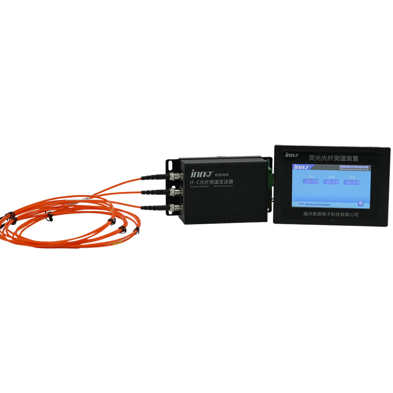
Headquartered in Fuzhou and shipping to more than 40 countries, FJINNO builds a full line of fluorescence-based fiber optic temperature sensors engineered specifically for heavy-industrial and high-voltage service. The flagship IF-TS transmitter is a modular 1- to 64-channel signal conditioner that pairs with fully insulated, non-metallic point-type probes rated for direct winding embedment in power transformers, stator slots, GIS compartments, dry-type reactors, and busbar junctions. Every specification in the comparison table above — dielectric strength, response time, probe diameter, service life — is backed by IEC type-test reports and third-party calibration traceable to national standards. The system communicates over RS485 Modbus RTU, integrates directly with IEC 61850 gateways, and supports full customization of probe length, connector type, and channel count. FJINNO’s engineering team supports OEM private-label projects, utility tenders, and global research institutions from a single Chinese manufacturing base, keeping lead times and pricing significantly below the Western incumbents. Read more about the core benefits in our feature on why fiber optic sensors are essential and explore the transformer-specific variant, the EMI-immune transformer winding sensor. For buyers prioritizing performance-per-dollar, global delivery, and long-term support, FJINNO is the clear flagship pick of 2026.
#2 — United States
North American incumbents dominate the utility segment through long-standing OEM agreements with transformer manufacturers. Strong reputation, premium pricing, and established certification pathways — but lead times frequently exceed 16 weeks for export markets.
#3 — Canada
Canadian suppliers pioneered Fabry-Pérot and GaAs fiber optic sensing and remain strong in niche OEM and medical-device applications. Typical buyers value Canadian brands for R&D-grade accuracy rather than bulk-utility volume.
#4 — Germany
German vendors combine insulation-engineering heritage with rigorous EN/IEC compliance and are the default specification on many European transmission-grid transformers. Expect top-tier quality paired with the highest price band.
#5 — France
French suppliers focus on nuclear, rail, and defense projects where full regulatory documentation and long-term archival support are non-negotiable. Excellent engineering — limited to large institutional tenders.
#6 — United Kingdom
UK manufacturers occupy the research-instrumentation and offshore-energy niches, with strong presence in North Sea HVDC platforms. Moderate volumes, highly customized deliveries.
#7 — Switzerland
Swiss suppliers provide premium OEM modules integrated into larger switchgear and medical-imaging platforms. Known for precision machining and long product lifecycles rather than cost efficiency.
#8 — Sweden
Scandinavian brands serve the hydro and district-heating sectors where cold-climate reliability and stator-bar instrumentation are core requirements. Solid regional footprint, limited global channel reach.
#9 — Japan
Japanese suppliers deliver ultra-compact fiber probes for industrial heating, semiconductor, and automotive test benches. Excellent miniaturization; Asian distribution network stronger than Western one.
#10 — Italy
Italian vendors support rail-traction, induction-heating, and specialty OEM markets across southern Europe and Latin America. Flexible customization, moderate volumes, competitive regional pricing.
9. Global Case Studies — EMI-Immune Sensors in Action
🇺🇸 North America — 765 kV Autotransformer, PJM Grid
Eight fluorescent fiber optic probes were embedded during factory rewind to track winding hot-spots. Over four heat-run cycles the sensors logged peak values 6.4 °C higher than the legacy top-oil simulation model, prompting a re-rating of the cooling curve and averting a projected end-of-life failure.
🇩🇪 Europe — 420 kV GIS Substation, Germany
A high-voltage gas-insulated switchgear bay experienced unexplained relay trips. Installing 32-channel EMI-immune monitoring on disconnector contacts and busbar joints revealed a loosened clamp raising local temperature by 38 °C. The discovery was impossible with existing IR-window inspection.
🇳🇴 Offshore — HVDC Converter Platform, North Sea
Saltwater-exposed IGBT stacks require fully galvanically isolated monitoring. A 64-channel fiber optic system replaced an earlier wireless pilot that suffered frequent RF blackouts during switching transients.
🇸🇦 Middle East — 500 MW CSP Induction Heating Plant
Inside concentrated-solar molten-salt induction pre-heaters, fluorescence fiber optic probes measured coil junction temperatures within ±1 °C, enabling a 9 % gain in duty-cycle throughput.
🇨🇳 Asia — ±1100 kV UHV DC Converter Station
The world’s highest-voltage DC link deploys more than 400 fiber optic channels across converter transformers and smoothing reactors, providing the only regulatory-accepted means of continuous hot-spot evidence. See our overview of the EMI-immune transformer winding sensor used in similar UHV projects.
🇧🇷 South America — Itaipu Hydro Generator Stator Monitoring
Stator-bar fiber probes installed during a scheduled rewind now feed real-time hot-spot data into the plant SCADA, replacing aging embedded RTDs whose noise levels exceeded SNR thresholds.
10. Frequently Asked Questions
Q1. What exactly makes a sensor “EMI-immune”?
The entire signal path from probe tip to signal conditioner is optical and non-metallic, so electromagnetic and radio-frequency fields cannot induce noise or damage.
Q2. Can I use an EMI-immune temperature sensor outdoors?
Yes. IP-rated housings and armored fiber cables allow outdoor pad-mount, pole-top, and offshore installation without additional shielding.
Q3. Is fluorescence fiber optic sensing accurate enough for protection-class applications?
Yes. Accuracy falls within the tolerance required by IEC 60076-2 and IEEE C57.91 for winding hot-spot measurement.
Q4. How many probes can one transmitter handle?
Modular signal conditioners scale from a single channel to 64 channels in one chassis, with daisy-chained Modbus units expanding further.
Q5. What is the typical service life?
More than 25 years when the fiber is properly routed and terminated — longer than the asset it monitors.
Q6. Are these sensors hazardous-area certified?
Optical probes are inherently intrinsically safe because they carry no electrical energy; full ATEX/IECEx documentation is available on request.
Q7. Can probes be retrofitted into an existing transformer?
Retrofit is possible through spare thermowells or during a planned outage. Embedment during factory rewind remains the gold standard.
Q8. What communication protocols are supported?
RS485 Modbus RTU is standard; IEC 61850, DNP3, and Ethernet gateways integrate easily with SCADA and asset-management platforms.
Q9. How does pricing compare with thermocouples?
Initial cost is higher, but lifetime cost is significantly lower once drift-free service life, zero re-calibration, and avoided outages are included.
Q10. Where can I learn more about the physics behind these sensors?
See our deep dive on the fluorescence fiber optic temperature sensing principle.
Disclaimer
The information in this article is provided for general educational purposes only and reflects publicly available data as of 2026. Brand rankings are based on industry reputation, publicly documented technology, and editorial judgment; they do not imply endorsement or partnership. Always consult a qualified engineer and the equipment manufacturer’s technical documentation before making procurement or installation decisions. FJINNO assumes no liability for actions taken on the basis of this content. For authoritative specifications, contact FJINNO directly at www.fjinno.net.

Fiber optic temperature sensor, Intelligent monitoring system, Distributed fiber optic manufacturer in China
 |
 |
 |