Fiber optic temperature sensor, Intelligent monitoring system, Distributed fiber optic manufacturer in China
 |
 |
 |
The subway power system generally consists of electrical equipment such as circuit breakers, transformers, rectifier cabinets, cables, busbars, etc. They are connected to each other by busbars, leads, cables, etc. The current flowing through the conductors and connecting parts will generate heat. Electrical equipment may have excessive local resistance due to long-term use or loose connections. When a large current passes through, it will generate high temperatures and even burn out the equipment. Therefore, the quality of the conductor connection part is the key to endangering the safe operation of the power supply system, and it is also the key to the online monitoring system of power supply equipment. The main forms of faults in power supply equipment are:
1. The main forms of faults in the circuit breaker cabinet are: eccentric and loose insertion of isolation plugs on the upper and lower parts of the circuit breaker cabinet, causing overheating, poor contact between the circuit breaker and external cable joints, resulting in heating and equipment damage.
2. The main forms of faults in transformers and rectifier cabinets are: poor contact of cable joints and conductor connections leading to overheating, accelerated insulation aging leading to breakdown, resulting in phase to phase short circuits, and even equipment burning.
3. The form of cable failure in crossing tracks through pipes is: damage occurs during cable crossing due to construction or external forces, displacement and wear of the cable due to train operation vibration, and maintenance personnel cannot detect the damage to the cable inside the pipe. Under long-term current thermal effects, this damage gradually expands and deepens, leading to multiple grounding points of the cable metal sheath, resulting in circulating current in the protective layer, increasing the loss of the sheath, and in severe cases, causing the cable to overheat and burn out.
4. The form of cable failure on the upper rail is: the connection between the upper rail cable and the contact rail is not tightly pressed or gradually loosened due to harsh outdoor environments, resulting in poor contact and heating. This not only affects the quality of power supply, but can even cause equipment damage due to ignition when overheated.
5. DC grid switch cabinet: Due to design reasons, it is not possible to monitor the position status of the equipment once (in this case, the auxiliary switch contact is abnormal and cannot be switched in place, and the defect situation cannot be grasped in a timely manner). It may be due to inadequate closing, resulting in poor contact of the conductor and burning, incomplete opening, resulting in incomplete power outage, causing accidental injury or electric shock accidents.
Monitoring methods for power supply equipment
1. Online monitoring of circuit breaker cabinet
9-point method: Monitor the engagement of 6 dynamic and static contacts and 3 inlet and outlet cable joints.
2. Online monitoring of transformers and rectifier cabinets
6-point and 9-point: Monitor all incoming and outgoing cable joints.
3. Invisible monitoring of cable insulation through rails and pipes
Using distributed optical fiber to monitor the insulation condition of the cable passing through the conduit section of the track passing cable.
4. Online monitoring of cable connection quality at three rail points
Monitor the connection quality between the upper rail cable and the contact rail connection point.
5. Online monitoring of DC grid switchgear
Monitor the position of the isolation switch.
Why does the traction power supply system of rail transit need to use fluorescent fiber optic temperature measurement
The power supply systems for traction power supply in urban rail transit in China are DC750V and DC1500V, corresponding to the current collection methods of the third rail and overhead contact network, respectively. The maximum voltage of the secondary winding of this power supply system’s transformer has exceeded 1000V, but the measurement range specified in the “Electronic Temperature Controller for Transformers” (JB/T7631-2016), which uses Pt100 as the temperature sensor, can only be limited to below 1000V. Therefore, rail transit has higher voltage resistance requirements for temperature sensor probes and leads.
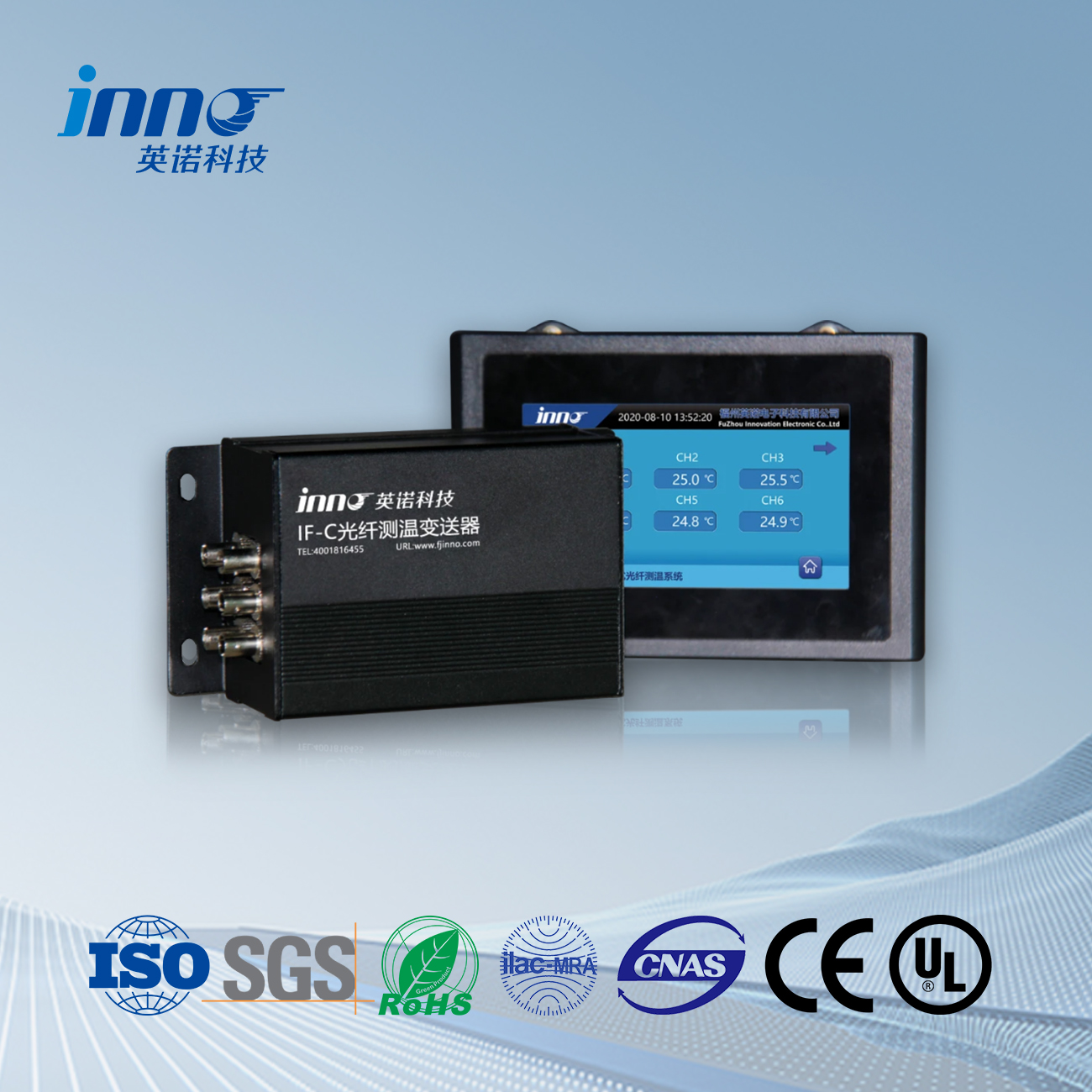
The fiber optic temperature controller for rail transit uses FJINNO’s fluorescent fiber optic temperature sensor as the temperature sensing element. This temperature sensing element is immune to electromagnetic interference and resistant to high voltage (100KV/fiber to ground lead distance of 0.4m). Fluorescent fiber optic temperature measurement completely cuts off the interference of temperature measurement elements transmitted to the temperature controller from the temperature measurement source, improving the safety level of rail transit.
Advantages of Fluorescent Fiber Optic Temperature Measurement System Applied in Rail Transit
For the operating environment of rail transit transformers, isolation and shielding from external electrical interference signals are achieved from the power supply, signal input end, signal output end, and temperature control box shell.
The power supply system of rail transit traction power supply is based on DC750V and DC1500V, while the measurement range specified in the “Electronic Temperature Controller for Transformers” (JB/T7631-2005), which uses Pt100 as the temperature sensor, can only be limited to below 1000V. Therefore, the fiber optic temperature controller has extremely strong voltage resistance and can withstand 100KV.
In response to vibration, dust, humidity, oil pollution and other on-site working environments, multi-layer protective measures are taken to ensure that the optical fiber temperature controller for rail transit has good electromagnetic compatibility, ensuring the stable and reliable operation of the temperature controller.
 INNO fibre optic temperature sensors ,temperature monitoring systems.
