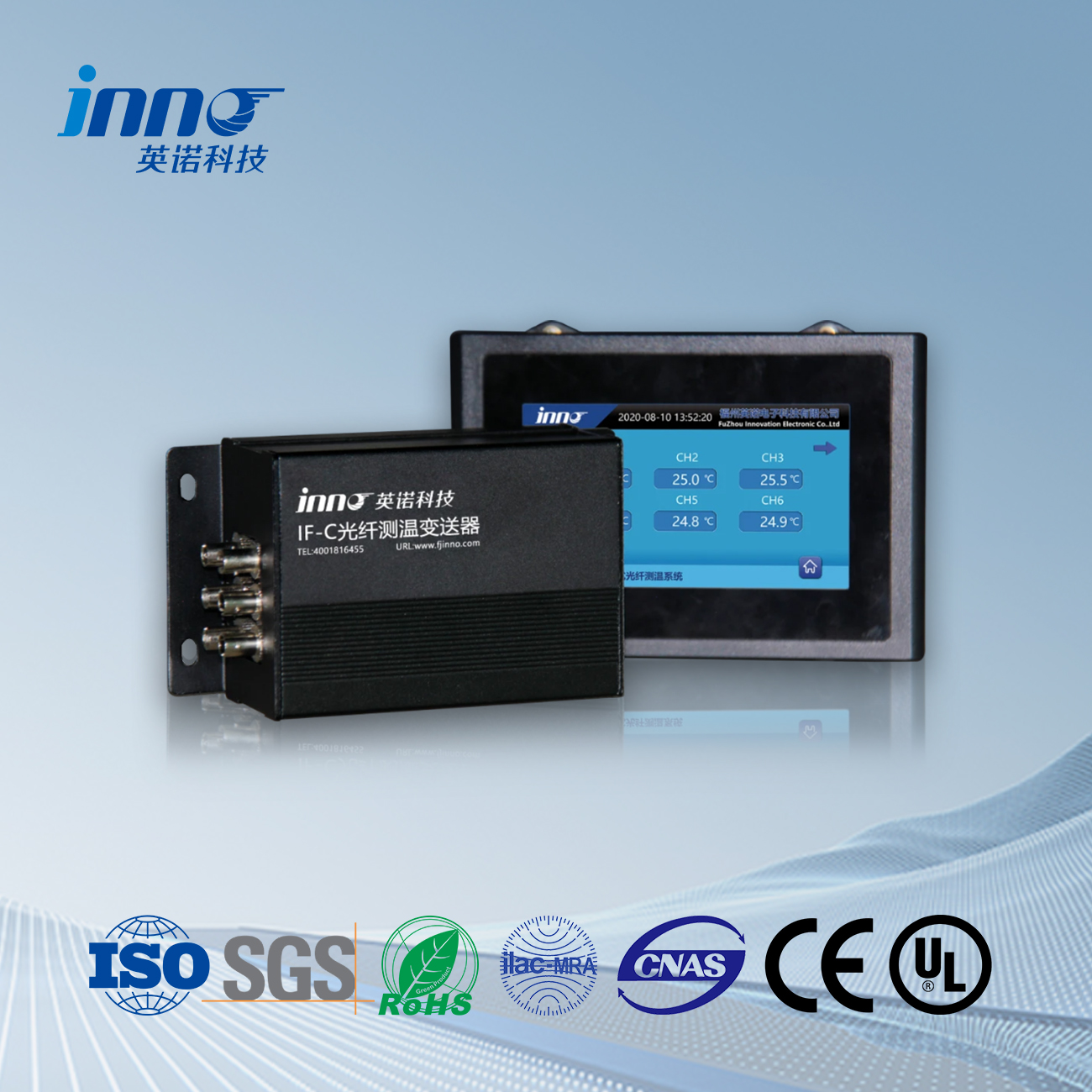
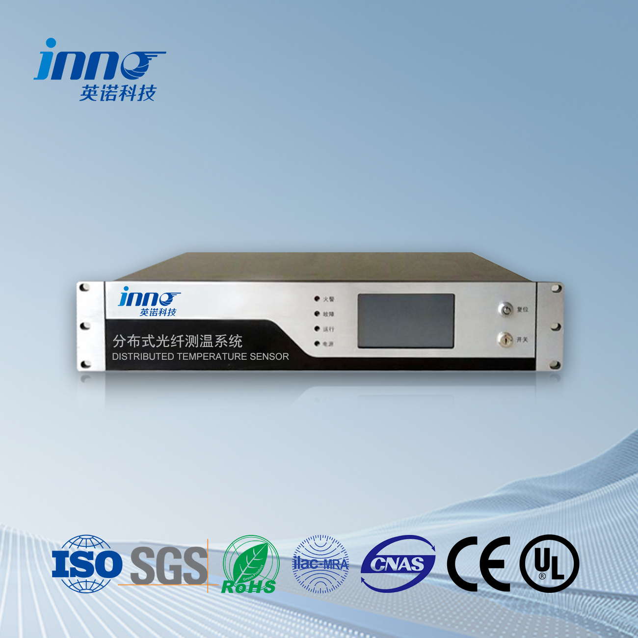
Fiber optic temperature measurement for switchgear contacts is an important technology for monitoring electrical equipment temperatures. There are primarily two types of fiber optic temperature sensors:
Fluorescence Fiber Optic Temperature Measurement
This method utilizes the temperature characteristics of fluorescent materials. Fluorescence fiber optic probes are installed at heat-prone areas such as switchgear contacts. Light from an excitation source is absorbed by the fluorescent material, which then emits fluorescence carrying temperature information. The fiber optic transmission unit transmits the excitation light to the probe and returns the fluorescence signal to the signal processing unit. After processing through photodetectors, amplifiers, filters, analog-to-digital converters, and other circuits, temperature characteristic information is extracted, enabling precise temperature calculation.
Fiber Bragg Grating Temperature Measurement
This method is based on the Bragg gratings principle in optical fibers. When temperature changes, the period and effective refractive index of the fiber Bragg grating change, causing a shift in the Bragg wavelength. By measuring this wavelength shift, the temperature value can be determined. This approach enables distributed temperature measurement of switchgear contacts with high accuracy and stability.
System Components
Temperature Transmitter/Demodulator Main Unit
This is the core control unit of the entire fiber optic temperature measurement system, responsible for controlling signal emission, reception, and processing. It typically includes light source drive circuits, photodetectors, signal processing circuits, data processors, and communication interfaces. These systems offer temperature resolution of 0.1°C, measurement accuracy of ±1°C, and rapid scanning across all channels.
Fluorescence Optical Fiber (with Sensing Head)
The fluorescence optical fiber serves as the temperature-sensitive element. Its probe is encapsulated with fluorescent material used to sense the temperature of the measured object and convert temperature information into optical signals transmitted to the temperature measurement main unit. The fiber offers excellent insulation properties and electromagnetic interference resistance, ensuring stable signal transmission in the complex electromagnetic environment of switchgear.
Optical Fiber Transmission Unit
This unit connects the temperature measurement main unit and the fluorescence fiber optic sensing head, transmitting optical signals between them. It must possess good optical performance and mechanical stability to ensure the quality and reliability of optical signal transmission.
Monitoring and Display Unit
This unit displays processed temperature data in real-time, allowing maintenance personnel to intuitively understand the temperature conditions at various measurement points within the switchgear. It also includes alarm functionality, issuing audio-visual alarm signals when temperatures exceed preset thresholds, alerting maintenance personnel to take action. Additionally, some monitoring systems support data storage, historical data queries, and analysis functions.
Advantages
Electromagnetic Interference Resistance
Strong electromagnetic fields exist around switchgear. Fiber optic temperature measurement systems are not affected by electromagnetic interference, ensuring accurate and reliable temperature data.
High Insulation and Safety
Fluorescence optical fibers possess excellent insulation properties with no risk of current leakage. When used in high-voltage switchgear environments, they ensure measurement safety without interfering with equipment operation.
Real-time Monitoring
These systems can monitor temperature changes at critical locations within switchgear in real-time, promptly detecting abnormal temperature rises, preventing overheating-induced failures, and improving switchgear operational reliability.
Long-term Stability
Once installed, fluorescence fiber optic probes require minimal maintenance and calibration, providing stable operation over extended periods, continuously delivering accurate temperature data, and reducing maintenance workload and costs.
Precise Localization
Fiber optic temperature sensors correspond to specific measurement point locations, allowing precise localization of alarming sensors through upper-level monitoring software.
Multi-point Measurement and Zoned Alarm Control
These systems easily implement multi-point temperature measurement and, through upper-level monitoring software, manage different measurement points in zones. Different alarm parameters can be set for each measurement point, such as temperature pre-warning, temperature rise pre-warning, temperature alarm, and temperature rise alarm, accurately distinguishing between genuine and false fire alarms, eliminating false alarms and missed alarms.
Installation Methods
Fluorescence Fiber Optic Probe Installation
After identifying heat-prone areas within the switchgear, such as bus bar connections and circuit breaker contacts, specialized mounting fixtures secure fluorescence fiber optic probes firmly to the surface of the measured object. During installation, ensure full contact between the probe and the measured object to accurately obtain temperature information. Consider the switchgear’s spatial layout and electrical safety distances to avoid affecting normal switchgear operation.
Fiber Optic Wiring
Route optical fibers according to the switchgear’s structure and predetermined paths. Fiber optic wiring should avoid parallel installation with high-current lines to prevent electromagnetic interference. Ensure the fiber’s bending radius meets requirements to prevent damage and maintain reliable optical signal transmission.
Application Case Study
In a switchgear renovation project at a substation, a temperature monitoring system based on fluorescence fiber optic temperature measurement was installed. By installing fluorescence fiber optic probes at multiple locations, including bus bar connections and circuit breaker contacts across several switchgear units, real-time temperature monitoring was achieved. After system deployment, abnormal temperature increases caused by poor contacts and other issues were effectively detected in some switchgear units, triggering timely alarm signals. Maintenance personnel used this information to perform repairs, preventing potential equipment failures and improving the substation’s power supply reliability.
Fiber optic temperature sensor, Intelligent monitoring system, Distributed fiber optic manufacturer in China
 |
 |
 |
 INNO fibre optic temperature sensors ,temperature monitoring systems.
