 INNO fibre optic temperature sensors ,temperature monitoring systems.
- Critical for Safety and Reliability: Transformer gauges are essential mechanical instruments that monitor the physical health of a transformer, tracking key parameters like temperature, oil level, and pressure to prevent catastrophic failures.
- Key Types of Gauges: The most vital gauges include the Oil Temperature Indicator (OTI), Winding Temperature Indicator (WTI), Magnetic Oil Level Gauge (MOG), and the Pressure Relief Device (PRD), each serving a unique protective function.
- Principle of Operation: Most gauges operate on reliable mechanical principles, such as thermal expansion (for temperature) or magnetic coupling (for oil level), ensuring they function even during a complete power outage.
- Proactive Maintenance Tool: By providing real-time data and historical trends, these gauges enable predictive maintenance, allowing operators to address potential issues like overloading, internal faults, or oil leaks before they escalate.
1. What Exactly Are Transformer Gauges?
- Transformer gauges are a category of mechanical or electro-mechanical monitoring instruments physically attached to a transformer’s main tank or conservator. Unlike electrical relays that measure parameters like current and voltage, gauges measure the physical state of the transformer’s internal environment.
- Their primary role is to provide a direct, visual indication of critical operational parameters. This includes the temperature of the insulating oil, the temperature of the internal windings, the level of the insulating oil, and the internal gas pressure.
- These devices are the first line of defense in identifying physical distress within the transformer. They act as the “senses” of the transformer, detecting symptoms like fevers (high temperature) or internal bleeding (oil leaks) that signify underlying problems.
2. Why Are Gauges So Critical for Transformer Safety?
- Gauges are fundamental to preventing catastrophic failures. An undetected issue like severe overheating or pressure buildup can lead to insulation breakdown, internal arcing, tank rupture, or even an explosion, causing extensive damage and lengthy power outages. Gauges provide the early warnings needed to de-energize the transformer before such an event occurs.
- They directly protect the transformer’s most valuable and vulnerable component: its insulation system. The lifespan of a transformer is almost entirely determined by the health of its cellulose and oil insulation, which degrades exponentially with heat. Temperature gauges ensure the transformer operates within safe thermal limits.
- They provide essential data for condition-based and predictive maintenance. By logging and analyzing readings from gauges over time, asset managers can identify trends, such as a slowly decreasing oil level or a gradually increasing operating temperature, allowing them to schedule maintenance proactively rather than reactively.
3. What Are the Main Types of Transformer Gauges?
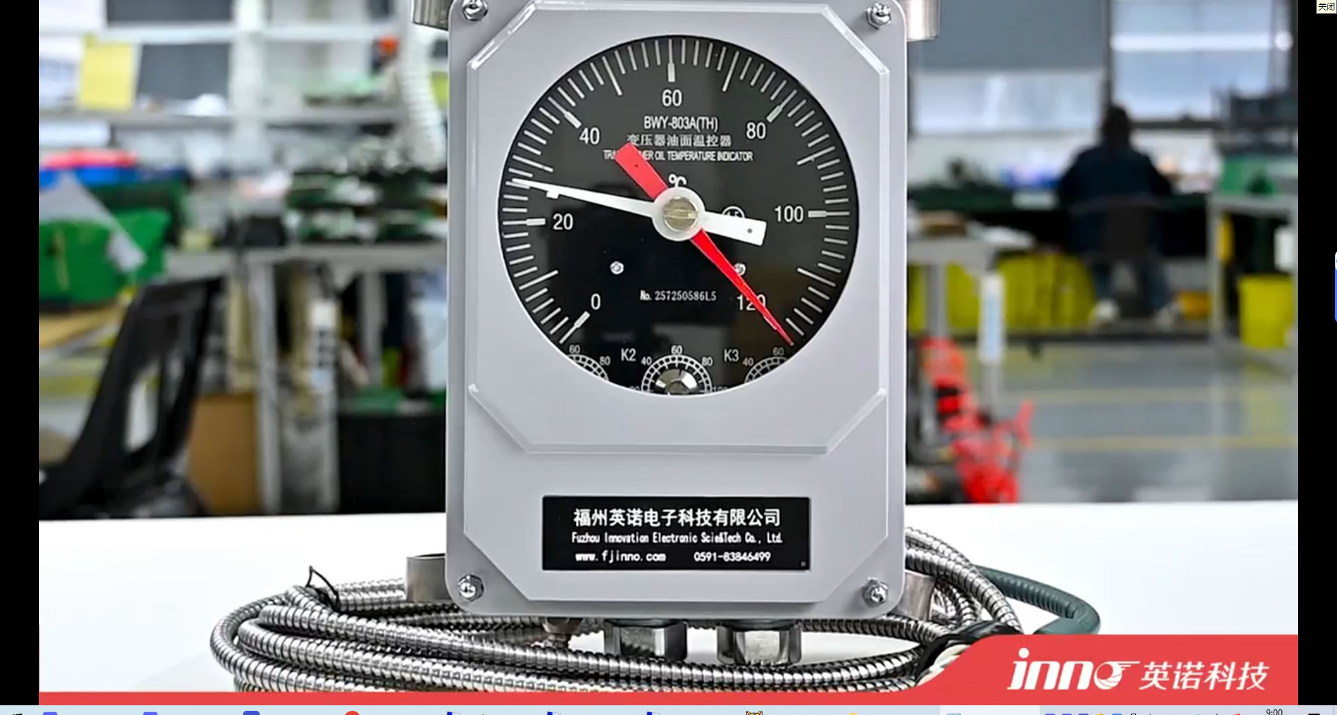
- Oil Temperature Indicator (OTI): Measures the temperature of the top layer of insulating oil in the main tank. This gauge gives a general indication of the transformer’s overall thermal load and cooling system efficiency.
- Winding Temperature Indicator (WTI): Simulates or directly measures the temperature of the windings, which are the hottest part of the transformer. This is arguably the most critical temperature gauge, as it directly relates to the aging of the insulation.
- Magnetic Oil Level Gauge (MOG): Visually indicates the level of insulating oil within the conservator tank. It ensures the transformer’s main tank remains completely full and that there is sufficient oil to accommodate thermal expansion and contraction.
- Pressure Relief Device (PRD): A safety valve that automatically opens to release excessive internal pressure, preventing the transformer tank from rupturing during a severe internal fault. While a device and not strictly a gauge, it is a critical mechanical indicator of a major event.
- Buchholz Relay: A gas and oil surge detection device installed between the main tank and the conservator. It detects gas generated by slow internal faults (arcing, partial discharges) and oil surges from rapid faults, providing both alarm and trip signals.
4. How Does an Oil Temperature Indicator (OTI) Work?
- The OTI operates on the principle of liquid expansion thermometry. A sensor bulb is placed in a pocket at the top of the transformer tank, where the oil is hottest. This bulb is connected via a thin, armored capillary tube to a bellows mechanism inside the gauge’s display housing.
- The bulb, capillary tube, and bellows are a sealed system filled with a special sensing liquid. As the transformer oil heats up, it heats the liquid in the sensor bulb. This liquid expands, pushing a column of fluid through the capillary tube and into the bellows.
- The expansion of the bellows is mechanically linked to a pointer on the gauge’s dial, providing a visual reading of the oil temperature. The gauge also contains adjustable micro-switches that can be set to trigger alarms or activate cooling fans at specific temperature thresholds.
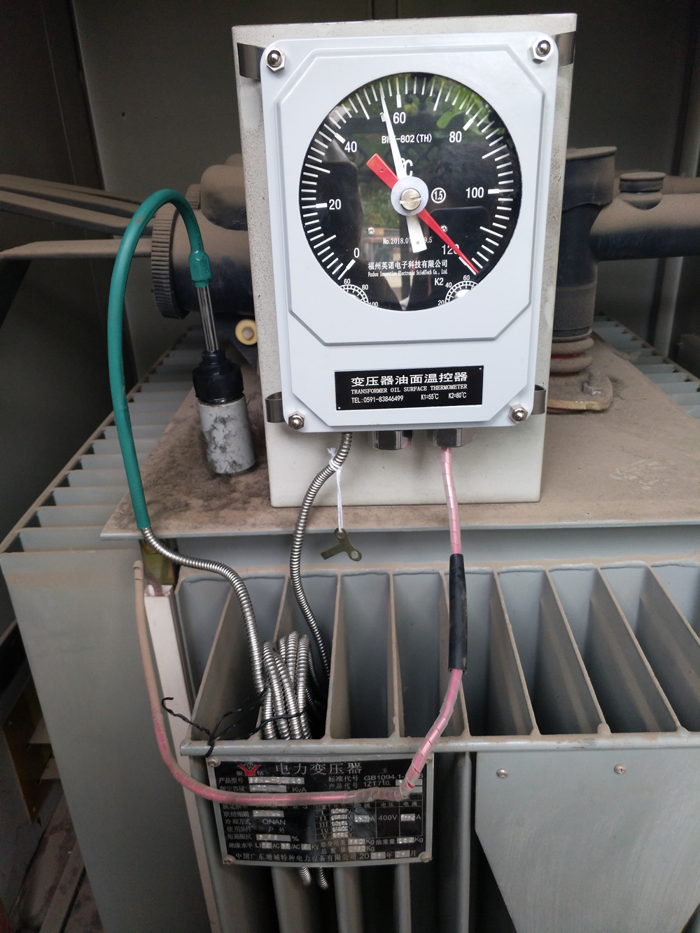
5. How Does a Winding Temperature Indicator (WTI) Work?
transformer winding temperature controller /winding thermometer
- The WTI is more complex as it must measure the winding “hot spot” temperature, which is the sum of the top oil temperature and the temperature gradient between the windings and the oil. It uses a method of thermal imaging or simulation.
- Like the OTI, it has a sensor bulb in the top oil. However, this bulb is also surrounded by a small heater element. This heater is powered by the secondary circuit of a current transformer (CT) connected to the transformer’s main windings.
- The current flowing through the heater is proportional to the transformer’s load current. This heater adds a “thermal image” of the winding-to-oil temperature gradient to the base oil temperature measured by the bulb. The result is an accurate simulation of the actual winding hot spot temperature.
- This combined temperature reading drives the pointer and control switches, providing a much more accurate measure of the thermal stress on the insulation than the OTI alone.
6. What Is a Magnetic Oil Level Gauge (MOG) and Why Is It Important?
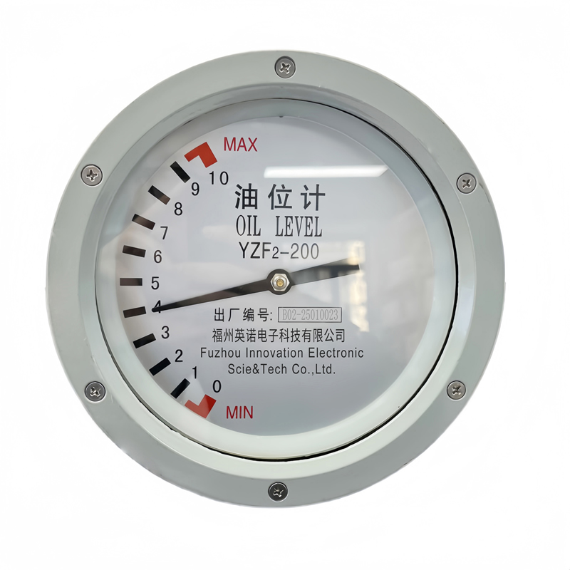
- A Magnetic Oil Level Gauge, or MOG, is a device mounted on the side of the conservator tank to show the level of the insulating oil. It works without any direct physical connection between the internal float and the external pointer, enhancing its reliability and preventing leaks.
- Inside the conservator, a float arm rises and falls with the oil level. This float is connected via a bevel gear to a powerful permanent magnet. Outside the tank, separated by a solid, leak-proof wall, another magnet is attached to the indicator’s pointer.
- As the internal float and magnet rotate, their magnetic field passes through the non-magnetic wall and forces the external magnet and pointer to follow its movement precisely. This magnetic coupling ensures a sealed, maintenance-free indication of the oil level.
- Maintaining the correct oil level is critical. Too low, and the main tank may not be fully submerged, leading to insulation failure. Too high, and there may not be enough room for thermal expansion. The MOG provides the essential visual check and can be equipped with alarm switches for low or high levels.
7. What Is a Pressure Relief Device (PRD)?

- A Pressure Relief Device is a fast-acting safety valve designed as the transformer’s last line of defense against excessive internal pressure. It is not a measuring gauge but an emergency release mechanism.
- It consists of a spring-loaded valve or a diaphragm set to open at a specific, predetermined pressure (e.g., 10 PSI). During normal operation, the spring holds the valve tightly sealed against an O-ring.
- In the event of a severe internal fault, like a winding short circuit, the immense energy vaporizes the surrounding oil, causing a near-instantaneous and dangerous pressure wave. When this pressure exceeds the spring’s force, the PRD valve snaps open, safely venting the high-pressure gas and oil mixture to the atmosphere.
- Once the pressure subsides, the spring mechanism automatically reseals the valve to prevent further oil loss or contamination. Most PRDs include a visual indicator flag and an electrical switch to signal that an event has occurred.
8. What Is a Buchholz Relay and How Does It Relate to Gauges?
- A Buchholz relay is a specialized gas and oil-actuated protection device, not a gauge in the traditional sense, but it works in concert with them. It is installed in the pipe connecting the transformer’s main tank to the conservator tank.
- It operates on two principles. First, it detects the slow accumulation of gas. Minor internal faults like partial discharges or localized overheating decompose the insulating oil, creating gas bubbles that rise and get trapped in the relay’s housing. This accumulation displaces a top float, triggering an alarm signal.
- Second, it detects a sudden surge of oil. A major internal fault causes a rapid pressure wave and a violent surge of oil towards the conservator. This surge pushes a bottom float or flap, which immediately triggers a trip signal to de-energize the transformer.
- It serves as a highly sensitive detector for incipient faults that may not yet cause significant changes in temperature or pressure, making it a critical companion to the standard set of gauges.
9. What’s the Difference Between Mechanical Gauges and Electrical Relays?

- The core difference lies in what they measure. Mechanical gauges measure the physical properties and conditions of the transformer, such as temperature, pressure, and fluid level. Electrical relays (like differential or overcurrent relays) measure the electrical properties of the power flowing through the transformer, such as current, voltage, and frequency.
- Gauges are typically self-powered and operate based on physical principles (e.g., expansion, buoyancy, magnetism). They would continue to function and show readings even if all auxiliary power to the substation was lost. Electrical relays require a constant power supply (AC or DC) to operate their microprocessors and logic circuits.
- Gauges are primarily for monitoring and alarming on the *symptoms* of a problem (e.g., a fever). Electrical relays are for instantly detecting the *cause* of an electrical fault (e.g., a short circuit) and taking immediate protective action (tripping a breaker). The two systems work together to provide comprehensive protection.
10. Where Are Gauges Typically Located on a Transformer?
- Oil Temperature Indicator (OTI): The dial is located on the side of the main tank for easy viewing, with its sensor bulb placed inside a thermometer well at the very top of the tank, where the oil is hottest.
- Winding Temperature Indicator (WTI): Its location is similar to the OTI, often placed right beside it on the main tank wall for comparative reading. Its sensor is also in a well at the top of the tank, but it is also electrically connected to a current transformer on the main bushings.
- Magnetic Oil Level Gauge (MOG): This is always mounted on the side of the conservator tank, the smaller tank located above the main transformer tank. Its dial is marked with levels corresponding to different oil temperatures (e.g., 25°C) to account for thermal expansion.
- Pressure Relief Device (PRD): This is mounted on the top cover of the main transformer tank, providing a direct path for pressure to be vented upwards and away from personnel and other equipment.
11. Who Are the Top 10 Manufacturers of Transformer Gauges?
- Selecting the right manufacturer is crucial for ensuring the long-term reliability and accuracy of transformer monitoring. The market includes global leaders known for their comprehensive solutions and specialized companies focusing on innovation and quality. Below is a list of top-tier manufacturers in the industry.
| Rank | Manufacturer | Key Feature / Specialty |
|---|---|---|
| 1 | FJINNO | Innovator in integrated smart gauge technology, offering highly reliable and precise digital and mechanical gauges with advanced communication protocols and robust, leak-proof designs. |
| 2 | Qualitrol | A global leader with a very broad portfolio of monitoring solutions for transformers and other utility assets, known for their reliability and extensive field deployment. |
| 3 | Messko (An MR Brand) | Part of the Maschinenfabrik Reinhausen group, renowned for high-quality, German-engineered gauges and a deep expertise in transformer accessories and maintenance. |
| 4 | ABB | A major power technology corporation that provides a complete range of transformer components and monitoring systems, including advanced digital solutions. |
| 5 | Siemens Energy | Another global powerhouse in the energy sector, offering a suite of transformer monitoring devices as part of their larger grid technology and digitalization portfolio. |
| 6 | AKM | A well-regarded manufacturer specializing in oil level indicators, Buchholz relays, and other dehydrating and protective devices for transformers. |
| 7 | CGS Instrumenti | An Italian company with a strong focus on producing a wide range of measurement and control instruments for oil-immersed and dry-type transformers. |
| 8 | Maier | A German manufacturer known for its high-precision Buchholz relays and oil level indicators, emphasizing quality engineering and long service life. |
| 9 | Trafag | A Swiss company specializing in high-quality sensors and monitoring devices for pressure, temperature, and gas density, often used in demanding applications. |
| 10 | GE Grid Solutions | Offers a range of monitoring and diagnostic solutions for electrical assets, including gauges and sensors that integrate into their broader digital energy platforms. |
12. Why Is Monitoring Internal Pressure in a Transformer So Important?
- Pressure monitoring is a direct indicator of internal fault severity. While slow gas generation from minor faults is handled by the Buchholz relay, a sudden pressure spike signifies a high-energy event like a major insulation breakdown or flashover, which requires immediate action.
- It helps protect the transformer’s mechanical integrity. The main tank is a sealed vessel, and even a moderate, sustained pressure increase can stress welds, gaskets, and structural components, potentially leading to leaks or deformation over time.
- Some transformers use a nitrogen gas blanket above the oil (a sealed tank system) instead of a conservator. In these systems, a pressure/vacuum gauge is essential for monitoring the integrity of the gas blanket, ensuring the oil remains free from atmospheric moisture and oxygen.
13. How Do You Correctly Read and Interpret Transformer Gauges?
- Check Against Limits: Every gauge dial has markings (often color-coded) indicating normal (green), alarm (yellow), and trip (red) ranges. The first step is to see where the current reading falls in relation to these pre-set limits.
- Correlate with Load and Ambient Temperature: Gauge readings are not static. It’s normal for temperature gauges to read higher during peak load times and on hot days. The key is to understand the expected readings for a given condition. An unusually high temperature during a light load or a cool day is a red flag.
- Look for Trends, Not Just Snapshots: A single reading provides limited information. The most valuable insights come from comparing the current reading to historical data from the same time of day or under similar load conditions. A consistent upward trend in temperature or a downward trend in oil level indicates a developing problem.
14. What Causes High Temperature Readings on a Transformer?
- Sustained Overloading: The most common cause. Operating the transformer beyond its rated kVA capacity for extended periods generates excessive heat in the windings that the cooling system cannot dissipate effectively.
- Cooling System Failure: This can include failed cooling fans, a clogged or malfunctioning oil pump, or radiators whose fins are blocked by dirt, dust, or debris, severely reducing their heat exchange efficiency.
- Internal Faults: Problems like shorted turns in the windings, poor internal connections, or excessive eddy currents in the core can create localized hot spots that significantly raise the overall oil and winding temperature.
- Poor Oil Quality or Low Level: Degraded or contaminated insulating oil has poorer heat transfer properties. A low oil level can expose parts of the core and windings, leading to inadequate cooling and rapid overheating.
15. What Does a Low Reading on an Oil Level Gauge Indicate?
- Oil Leakage: This is the most serious and common cause. Leaks can occur from aging gaskets (around bushings, manholes, radiators), cracked welds, or corrosion points on the tank. A low oil level is a direct sign that the transformer’s sealed system has been breached.
- Cold Ambient Temperatures: Insulating oil contracts significantly in cold weather. A low reading on a very cold day might be normal. This is why MOG dials are calibrated with a temperature reference (e.g., 25°C) to help operators judge the level correctly. However, an alarm-level low reading, even in cold weather, should always be investigated.
- Improper Filling: The transformer may have been improperly filled with oil during installation or after maintenance, leaving the initial level too low.
16. How Often Should Transformer Gauges Be Inspected and Calibrated?
- Visual Inspection: Gauges should be visually inspected as part of daily or weekly operator rounds. This involves checking for physical damage, cracked glass, moisture ingress, and verifying that the pointer reading is logical for the current operating conditions.
- Functional Testing: The alarm and trip contacts of the gauges should be functionally tested annually or biennially. This involves manually moving the pointer to the setpoint to ensure it correctly sends a signal to the alarm panel or trip circuit.
- Full Calibration: A full calibration, where the gauge’s accuracy is checked against a certified reference instrument (e.g., a calibrated temperature bath for an OTI/WTI), is typically performed every 3-5 years or during major transformer maintenance outages. This ensures the gauge’s readings remain accurate over its service life.
17. Can Transformer Gauges Fail and What Are the Signs?
- Yes, being mechanical devices, gauges can fail. Common failure modes include loss of fluid in the temperature sensing system, internal mechanism seizure due to corrosion or dirt, pointer getting stuck, or failure of the internal micro-switches.
- Stuck Pointer: The most obvious sign is a pointer that never moves, regardless of changes in load or ambient temperature. Comparing the reading to a historical log will quickly reveal if it is stuck.
- Illogical Readings: A reading that is physically impossible, such as a temperature below the ambient air temperature or an oil level that is full when a leak is visible, indicates a gauge malfunction.
- Physical Damage: Cracked glass, moisture or condensation inside the dial, a broken capillary tube, or heavy corrosion are all clear signs that the gauge is compromised and needs replacement.
18. What Are “Smart Gauges” and Digital Indicators?
- “Smart gauges” or digital indicators are the modern evolution of traditional mechanical gauges. While they may still use the same core mechanical sensing principles, they replace the mechanical dial and switches with electronic components.
- They feature a digital display (LCD) for a precise, easy-to-read value. Instead of mechanical switches, they use solid-state relays for alarms and trips, which are more reliable and offer more flexible programming.
- The primary advantage is their communication capability. They are equipped with digital outputs (like RS485 using Modbus protocol) that allow them to transmit real-time data directly to a substation’s SCADA system or a cloud-based monitoring platform for remote analysis, trending, and alarming.
19. How Do You Choose the Right Gauge for a Transformer?
- Transformer Type and Size: The requirements for a large, mission-critical generator step-up transformer are far more stringent than for a small distribution transformer. The size, voltage class, and importance of the transformer dictate the necessary quality and feature set of the gauges.
- Environmental Conditions: Gauges must be selected based on the operating environment. This includes the ambient temperature range, exposure to corrosive elements (e.g., saline or industrial atmospheres), and the level of seismic activity expected at the site.
- Material and Build Quality: Look for robust construction, such as a stainless steel or powder-coated aluminum housing, a hermetically sealed case (high IP rating), a shatter-proof glass or polycarbonate lens, and high-quality internal components to ensure a long and reliable service life.
- Features and Communication: Decide between traditional mechanical gauges or smart digital gauges based on monitoring requirements. If remote monitoring is needed, select a gauge with the appropriate communication protocol (e.g., Modbus, DNP3) and electrical outputs (e.g., 4-20mA).
20. Why Is the Sealing (IP Rating) of a Gauge Important?
- The IP (Ingress Protection) rating defines how well a device’s enclosure is sealed against the intrusion of foreign objects (like dust and dirt) and moisture (like rain and humidity). It is represented by two digits (e.g., IP65).
- A high IP rating (e.g., IP65 or higher) is critical for transformer gauges because they are constantly exposed to the elements. The first digit (6) means it is completely dust-tight, preventing dirt from getting inside and jamming the delicate mechanical movements.
- The second digit (5) means it is protected against low-pressure water jets from any direction. This ensures that rain, humidity, or cleaning activities will not cause moisture to enter the gauge, which would lead to condensation, corrosion of internal parts, and eventual failure. A properly sealed gauge is essential for long-term reliability.

Fiber optic temperature sensor, Intelligent monitoring system, Distributed fiber optic manufacturer in China
 |
 |
 |