 Sensor suhu serat optik INNO ,sistem pemantauan suhu.
Daftar isi
- Mengapa Transformator Daya Membutuhkan Pemantauan Suhu Serat Optik
- Manfaat Utama Pemantauan Suhu Serat Optik untuk Transformator
- Memahami Teknologi Sensor Suhu Fiber Optic untuk Transformer
- Melangkah 1: Merencanakan Sistem Pemantauan Suhu Transformator Anda
- Melangkah 2: Memilih Sensor Suhu Serat Optik yang Tepat
- Melangkah 3: Menentukan Titik Pemasangan Sensor Optimal
- Melangkah 4: Metode Instalasi dan Praktik Terbaik
- Melangkah 5: Menyiapkan Peralatan Interogasi dan Pengambilan Data
- Melangkah 6: Integrasi dengan Sistem Pemantauan Transformer
- Melangkah 7: Mengonfigurasi Ambang Batas Alarm dan Sistem Pemberitahuan
- Melangkah 8: Verifikasi dan Komisioning Sistem
- Persyaratan Perawatan dan Kalibrasi
- Studi Kasus Implementasi Dunia Nyata
- Memilih Produsen Sensor Suhu Serat Optik
- Pertanyaan yang Sering Diajukan
Mengapa Transformator Daya Membutuhkan Pemantauan Suhu Serat Optik
Transformator daya merupakan salah satu komponen paling penting dan mahal dalam sistem tenaga listrik. Aset penting ini biasanya bernilai jutaan dolar, dengan umur layanan yang diharapkan sebesar 30-40 tahun bila dipelihara dengan baik. Namun, Kegagalan trafo dapat menyebabkan pemadaman listrik yang sangat besar, mengakibatkan kerugian ekonomi yang signifikan dan potensi bahaya keselamatan.
Manajemen suhu adalah faktor terpenting dalam transformator health and longevity. Menurut standar IEEE, transformer insulation aging accelerates exponentially with temperature increases—for every 6-8°C rise above rated temperature, insulation life is typically halved. Hal ini membuat akurat, reliable temperature monitoring essential for optimal transformer operation and maintenance.
The Limitations of Traditional Temperature Monitoring Approaches
Konvensional pemantauan suhu transformator methods face significant limitations:
- Indikator Suhu Berliku (WTI): These use thermal models to estimate winding temperatures based on top oil measurements dan memuat arus. Meskipun banyak digunakan, they provide only calculated estimates rather than direct measurements, with accuracy typically ±5-10°C under dynamic conditions.
- Detektor Suhu Resistansi (RTD): These can only be placed in oil pockets, not directly in windings, menciptakan gradien suhu yang signifikan antara titik pengukuran dan hotspot sebenarnya.
- Termografi Inframerah: Terbatas pada pengukuran permukaan luar, tidak dapat mendeteksi hotspot internal tempat kegagalan kritis biasanya terjadi.
- Interferensi Elektromagnetik: Sensor elektronik konvensional rentan terhadap medan elektromagnetik intens yang ada pada transformator, mengarah ke kesalahan pengukuran dan peralatan potensial kerusakan.
Keterbatasan ini sering kali mengakibatkan praktik pembebanan konservatif sehingga kurang memanfaatkan kapasitas trafo, atau sebaliknya, hotspot yang tidak terdeteksi yang dapat menyebabkan kegagalan dini.
Solusi Pemantauan Suhu Serat Optik
Sensor suhu serat optik teknologi telah muncul sebagai standar emas untuk pemantauan suhu transformator, memberikan kemampuan yang tidak dapat ditandingi oleh metode konvensional:
- Pengukuran Hotspot Langsung: Sensor serat optik dapat ditanam langsung di dalam belitan transformator during manufacturing or retrofit, measuring actual hotspot temperatures rather than estimates.
- Imunitas EMI Lengkap: With no metallic components, probe suhu serat optik benar-benar kebal terhadap interferensi elektromagnetik, providing reliable readings regardless of transformer loading.
- Akurasi Tinggi: Modern sistem pengukuran suhu serat optik achieve accuracy of ±1°C or better, compared to ±5-10°C for conventional methods under dynamic conditions.
- Kemampuan Multi-Titik: Tunggal fiber optic temperature monitoring system can measure lusinan atau bahkan ratusan titik secara bersamaan, enabling comprehensive thermal mapping of complex transformer geometries.
- Data Waktu Nyata: Continuous monitoring with rapid response times captures transient temperature events that periodic measurements might miss, crucial during overload conditions.
These advantages make Penginderaan Suhu Serat Optik the preferred solution for critical transformers, particularly in transmission substations, generator step-up applications, and industrial settings where reliability is paramount.
Modern power transformer equipped with fiber optic temperature monitoring system, showing fiber routing and interrogation equipment.
Manfaat Utama Pemantauan Suhu Serat Optik untuk Transformator
Menerapkan fiber optic temperature measurement systems for power transformers delivers multiple tangible benefits that directly impact operational reliability, praktik pemeliharaan, asset life, and financial performance.
Kehidupan Transformator yang Diperpanjang
Tepat pemantauan suhu enables operators to prevent damaging thermal events and optimize loading within safe limits:
- Typical transformer life extension of 5-15 years through optimized thermal management
- Early detection of abnormal heating patterns before insulation damage occurs
- Reduced thermal aging rate through more precise loading control
- Historical temperature data enables accurate remaining life assessment
Untuk trafo kritis bernilai jutaan dolar, memperpanjang umur layanan bahkan beberapa tahun memberikan manfaat finansial yang besar dan belanja modal yang ditangguhkan.
Peningkatan Kapasitas Pemuatan
Berliku langsung Pengukuran suhu memungkinkan utilitas untuk memaksimalkan kapasitas trafo dengan aman:
- Peningkatan kapasitas tipikal sebesar 10-15% dibandingkan dengan pembebanan konservatif berdasarkan model termal
- Keyakinan untuk memanfaatkan peringkat darurat jangka pendek selama periode kritis
- Kemampuan pemuatan dinamis berdasarkan aktual suhu terukur daripada asumsi terburuk
- Pendinginan yang dioptimalkan Kontrol berdasarkan suhu waktu nyata data
Peningkatan kapasitas ini dapat menunda peningkatan infrastruktur yang mahal dan memberikan fleksibilitas penting selama periode permintaan puncak atau situasi darurat.
Deteksi Kesalahan Dini
Sensor suhu serat optik dapat mengidentifikasi permasalahan yang berkembang sebelum berkembang menjadi kegagalan yang sangat besar:
- Deteksi pendinginan yang tersumbat saluran melalui suhu lokal meningkat
- Identifikasi kerusakan sambungan listrik melalui pola pemanasan yang tidak normal
- Peringatan dini kerusakan isolasi melalui pembangunan hotspot
- Pengakuan pendinginan kegagalan sistem melalui suhu pola respons
Identifikasi dini terhadap permasalahan ini memungkinkan dilakukannya intervensi pemeliharaan terencana dibandingkan perbaikan darurat atau penggantian setelah terjadi kegagalan.
Praktik Perawatan yang Dioptimalkan
Data suhu yang komprehensif memungkinkan transisi dari pemeliharaan berbasis waktu ke pemeliharaan berbasis kondisi:
- Prioritas pemeliharaan berdasarkan riwayat tekanan termal aktual
- Inspeksi yang ditargetkan dipandu oleh anomali suhu
- Pengurangan aktivitas pemeliharaan preventif yang tidak perlu
- Penilaian kesehatan trafo yang lebih akurat untuk manajemen armada
These optimized maintenance practices typically reduce maintenance costs by 15-25% while simultaneously improving reliability and extending asset kehidupan.
Enhanced Safety and Environmental Protection
Preventing transformer thermal failures has significant safety and environmental benefits:
- Reduced risk of catastrophic failures that could result in fires or explosions
- Prevention of oil leaks and spills associated with thermal runaway events
- Enhanced personnel safety through remote monitoring that reduces inspection requirements
- Reduced risk of collateral damage to adjacent equipment during failure events
These benefits are particularly important for transformers located in environmentally sensitive areas or populated locations where safety hazards are heightened.
Comprehensive Documentation and Analytics
Modern sistem pemantauan suhu serat optik provide powerful data management capabilities:
- Complete temperature history for warranty claims and insurance documentation
- Advanced analytics for thermal performance optimization
- Integration with asset health sistem manajemen untuk penilaian kondisi yang komprehensif
- Valuable data for future transformer design and specification improvements
This wealth of data transforms temperature monitoring from a simple protection function to a valuable asset management tool with both operational and strategic benefits.
Pengembalian Investasi
The financial case for pemantauan suhu serat optik menarik. Case studies across utilities worldwide have documented:
- ROI periods typically ranging from 2-4 years for critical transformers
- Failure prevention savings of $500,000 ke $3 million per avoided major failure (including replacement costs, emergency response, dan dampak pemadaman)
- Capacity deferral savings of $1-2 million per substation where transformer upgrades can be postponed through optimized loading
- Maintenance savings of $15,000-$25,000 annually per large transformer through condition-based approaches
These financial benefits make pemantauan suhu serat optik a sound investment, particularly for large power transformers in critical applications.
Memahami Teknologi Sensor Suhu Fiber Optic untuk Transformer
Before implementing a fiber optic sistem pemantauan suhu untuk transformator daya, it’s essential to understand the different technologies available and their specific advantages for transformer applications.
Primary Fiber Optic Temperature Sensing Technologies
Two main fiber optic temperature sensor technologies dominate the transformer monitoring pasar, masing-masing dengan karakteristik yang berbeda:
Peluruhan Fluoresensi (GaA) Teknologi
This technology uses the temperature-dependent fluorescence decay time of gallium arsenide (GaA) semiconductor material at the tip of an optical fiber:
- Prinsip Operasi: Saat bersemangat dengan denyut nadi yang ringan, the GaAs material emits fluorescence with a decay time that precisely correlates to absolute temperature.
- Rentang Pengukuran: Typically -40°C to +250°C, ideal for transformer applications.
- Ketepatan: ±0.5°C or better across the measurement range.
- Keuntungan Utama:
- Point-specific measurements with high accuracy
- Mutlak temperature measurement requiring tidak ada kalibrasi
- Simple installation with minimal fiber handling
- Proven long-term stability in transformer environments
- Keterbatasan:
- Setiap titik penginderaan memerlukan seratnya sendiri
- Kemampuan penginderaan terdistribusi terbatas
- Terbaik Untuk: Kritis pemantauan hotspot secara spesifik, lokasi yang diketahui seperti hotspot berkelok-kelok, pintu keluar timah, dan sambungan inti.
Kisi Fiber Bragg (FBG) Teknologi
Sensor FBG gunakan kisi-kisi yang ditulis ke dalam inti serat yang memantulkan panjang gelombang cahaya tertentu berdasarkan suhu:
- Prinsip Operasi: Perubahan suhu menyebabkan kisi-kisi periode untuk ekspansi atau kontraksi, menggeser panjang gelombang cahaya yang dipantulkan sebanding dengan suhu.
- Rentang Pengukuran: Biasanya -40°C hingga +300°C dengan serat khusus dan pengemasan.
- Ketepatan: Biasanya ±1°C setelah kalibrasi.
- Keuntungan Utama:
- Beberapa sensor (20+ poin) pada satu serat
- Kemampuan multiplexing yang sangat baik untuk pemantauan komprehensif
- Mengurangi jumlah serat untuk instalasi yang rumit
- Gabungan kemampuan penginderaan suhu dan regangan
- Keterbatasan:
- Memerlukan kalibrasi awal dan kompensasi suhu
- Pemrosesan sinyal dan interpretasi data yang lebih kompleks
- Terbaik Untuk: Aplikasi yang membutuhkan banyak titik pengukuran, pemetaan termal yang komprehensif, dan gabungan pemantauan suhu/regangan.
Penginderaan Suhu Terdistribusi (DTS)
Sistem DTS mengukur suhu continuously along the entire length of an optical fiber:
- Prinsip Operasi: Berdasarkan Raman atau cemerlang backscattering, where the temperature-dependent scattered light is analyzed to determine temperature profiles.
- Rentang Pengukuran: Typically -40°C to +300°C depending on fiber coating.
- Resolusi Spasial: 0.5 ke 2 meter khas, dengan measurement distances hingga 30 km.
- Keuntungan Utama:
- Kontinu profil suhu sepanjang seluruh serat panjang
- No need to predetermine measurement points
- Thousands of effective measurement points with a single fiber
- Ideal for large or complex transformer structures
- Keterbatasan:
- Lower spatial resolution compared to point sensors
- Higher cost for interrogation equipment
- More complex installation and data interpretation
- Terbaik Untuk: Large transformers requiring comprehensive thermal mapping, and applications where hotspot locations are not known in advance.
Selecting the Optimal Technology for Your Application
The best technology choice depends on several factors specific to your pemantauan transformator persyaratan:
| Faktor | Peluruhan Fluoresensi (GaA) | Kisi Fiber Bragg (FBG) | Penginderaan Terdistribusi (DTS) |
|---|---|---|---|
| Jumlah titik pengukuran yang dibutuhkan | 1-8 poin | 8-40 poin | Profil berkelanjutan (thousands of points) |
| Transformer size and complexity | Small to medium | Sedang hingga besar | Large or complex geometry |
| Installation type | Factory or retrofit | Primarily factory | Factory or surface routing |
| Persyaratan akurasi | Paling tinggi (±0,5°C) | Tinggi (±1°C) | Sedang (±2°C) |
| Budget considerations | Biaya peralatan awal yang lebih rendah | Moderate system cost | Biaya peralatan lebih tinggi |
| Kompleksitas instalasi | Simpler | Sedang | More complex |
Many utilities implement hybrid approaches, using point sensors (Fluoresensi atau FBG) for known hotspots and DTS for broader thermal mapping of large transformers. Consulting with experienced produsen sensor suhu serat optik like FJINNO can help determine the optimal technology mix for your specific transformer fleet.

Visual comparison of the three primary Penginderaan Suhu Serat Optik technologies used in transformer applications, showing sensor design and installation differences.
Melangkah 1: Merencanakan Sistem Pemantauan Suhu Transformator Anda
Successful implementation of a fiber optic sistem pemantauan suhu begins with comprehensive planning that addresses technical requirements, operational goals, and implementation logistics.
Define Monitoring Objectives and Requirements
Begin by clearly establishing what you need to accomplish with your sistem pemantauan suhu:
- Primary Goals: Determine whether your focus is on trafo perluasan kehidupan, increasing loading capacity, improving maintenance practices, or some combination of these objectives.
- Criticality Assessment: Evaluate the strategic importance of the transformer(S) to prioritize implementation and determine appropriate investment levels. Consider factors like:
- Replacement cost and lead time
- Load served and redundancy available
- Historical reliability issues
- Age and condition relative to expected life
- Regulatory Requirements: Identify any applicable regulatory mandates or standards for temperature monitoring in your jurisdiction.
- Data Integration Needs: Determine how temperature data will integrate with existing asset management, SCADA, or condition sistem pemantauan.
Documenting these requirements provides the foundation for system specification and guides technology selection keputusan.
Gather Essential Transformer Information
Collect detailed information about the transformer(S) to be monitored:
- Design Documentation: Gather transformer design drawings, particularly winding details and cooling system layouts.
- Batas Suhu: Document specified temperature limits from nameplate or manufacturer documentation:
- Rata-rata suhu belitan bangkit
- Hotspot temperature rise
- Puncak suhu minyak bangkit
- Insulation system thermal class
- Data Historis: Collect any available historical temperature data from existing monitoring systems.
- Loading Profile: Analyze typical loading patterns and identify peak loading periods or seasonal variations.
- Accessibility Information: Document access points, available ports, and physical constraints that may affect installation.
This information is essential for determining optimal sensor placement and establishing appropriate alarm ambang batas.
Installation Timing Considerations
Determine the optimal timing and approach for installation:
- New Transformer Specification: For new units, sensor suhu serat optik should be specified during the procurement process and installed during manufacturing for optimal placement within windings.
- Retrofit Options: Untuk trafo yang ada, evaluate retrofit possibilities:
- Planned outage coordination
- Factory refurbishment opportunities
- Non-invasive installation options
- Outage Requirements: Document any operational constraints on outage duration or timing.
- Coordination with Other Work: Identify opportunities to combine pemasangan sensor suhu with other maintenance or upgrade activities.
Early planning of installation timing can significantly reduce costs and minimize operational impacts.
Budget and Resource Planning
Develop a comprehensive budget and resource plan:
- Komponen Sistem: Budget for all system elements:
- Fiber optic temperature sensors and probes
- Serat optik and feedthroughs
- Signal conditioning and interrogation equipment
- Monitoring software and integration components
- Installation materials and accessories
- Installation Resources: Determine whether installation will be performed by:
- Transformer manufacturer (for new units)
- Khusus Sensor serat optik installation contractors
- In-house technical staff with appropriate training
- Dukungan Berkelanjutan: Budget for maintenance, Kalibrasi, dan dukungan teknis.
- Persyaratan Pelatihan: Plan for training of operations and maintenance personnel.
Comprehensive budgeting helps avoid mid-project surprises and ensures all necessary components are accounted for.
Risk Assessment and Mitigation
Identify potential risks and develop mitigation strategies:
- Technical Risks: Compatibility issues, installation challenges, or integration problems.
- Operational Risks: Potential impacts on transformer availability or performance.
- Schedule Risks: Delays in equipment delivery, instalasi, atau komisioning.
- Strategi Mitigasi: Develop specific approaches to address each identified risk.
Proactive risk management increases the likelihood of successful implementation with minimal disruption.
Planning Checklist
Use this checklist to ensure comprehensive planning:
Melangkah 2: Memilih Sensor Suhu Serat Optik yang Tepat
Memilih yang sesuai fiber optic temperature sensors for your transformer application is critical for system performance, Keandalan, dan nilai jangka panjang. This selection process should consider both technical capabilities and practical implementation factors.
Key Selection Criteria for Transformer Applications
Evaluate potential sensor suhu serat optik against these essential criteria:
Kisaran Suhu dan Akurasi
Pastikan selected sensors meet the specific requirements of transformer aplikasi:
- Jangkauan Operasi: Sensors should cover the full temperature range of transformer operasi, typically from -40°C to at least +150°C for standard units and up to +180°C for overload conditions.
- Ketepatan: Look for accuracy of ±1°C or better across the operating range, particularly at critical temperature thresholds around 110-140°C where thermal aging accelerates.
- Resolusi: 0.1°C resolution is typically required for trend analysis and subtle anomaly detection.
- Stabilitas: Long-term stability with minimal drift over years of operation is essential for transformer lifetime monitoring.
Daya Tahan Lingkungan
Transformer environments are demanding, requiring sensors designed for harsh conditions:
- Kompatibilitas Minyak: Sensors must be compatible with transformer minyak mineral, natural ester fluids, or synthetic insulating fluids without degradation over decades.
- Ketahanan Kimia: Must withstand exposure to minyak transformator additives, gas terlarut, dan produk sampingan penuaan.
- Kekuatan Dielektrik: All materials must maintain appropriate dielectric properties in high-voltage environments.
- Daya Tahan Mekanis: Must withstand vibration, siklus termal, and physical stresses within the transformer.
- Expected Lifetime: Sensor lifetime should match or exceed the remaining transformer life, khas 25+ Tahun.
Pertimbangan Instalasi dan Integrasi
Practical implementation factors significantly impact system success:
- Form Factor: Sensor size and shape must be compatible with available installation spaces within the transformer.
- Metode Instalasi: Consider whether sensors will be factory-installed during construction or retrofitted to existing units.
- Feedthrough Options: Evaluate tank wall penetration options that maintain oil seal integrity and dielectric strength.
- Fiber Management: Consider fiber routing, batasan radius tikungan, and protection methods both inside and outside the transformer.
- Konektivitas: Ensure compatibility with selected interrogation equipment and availability of appropriate connectors.
Sertifikasi dan Kepatuhan Standar
Verify that sensors meet relevant industry standards and certifications:
- Standar IEEE: Compliance with IEEE C57.91 for transformer loading and temperature monitoring.
- Standar IEC: Adherence to relevant IEC standards for transformer monitoring and peralatan listrik.
- Material Safety: Certification that all materials are compatible with transformer insulating systems.
- Jaminan Kualitas: ISO 9001 certification for manufacturing processes.
- Hazardous Location: Appropriate certifications if installed in classified hazardous locations.
Support and Documentation
Comprehensive support is essential for successful long-term implementation:
- Installation Documentation: Detailed installation guidelines specific to transformer applications.
- Sertifikat Kalibrasi: Individual calibration data and traceability for each sensor.
- Dukungan Teknis: Availability of expert technical support for installation and troubleshooting.
- Warranty Terms: Comprehensive warranty appropriate for long-life transformer applications.
- Repair/Replacement Options: Clear procedures for addressing any sensor issues that may arise.
Comparison of Leading Fiber Optic Temperature Sensor Options for Transformers
The table below compares key specifications of fiber optic temperature sensors commonly used in transformer applications:
| Spesifikasi | Standard Transformer Sensor | High-Temperature Sensor | Solusi Retrofit |
|---|---|---|---|
| Kisaran Suhu | -40°C hingga +200 °C | -40°C hingga +300 °C | -40°C hingga +180 °C |
| Ketepatan | ±0,5°C | ±1,0°C | ±1,0°C |
| Waktu Respons | < 1 kedua | < 1 kedua | 1-2 Detik |
| Diameter Sensornya | 0.8 – 1.2 Mm | 1.2 – 2.0 Mm | 2.0 – 3.0 Mm |
| Instalasi Khas | Factory integrated | Factory integrated | Field retrofit |
| Expected Lifetime | 25+ Tahun | 25+ Tahun | 20+ Tahun |
| Optimal Applications | Baru transformator daya | High-temperature designs | Existing transformers |
Selection should be based on your specific tipe transformator, installation approach, dan tujuan pemantauan. Produsen terkemuka like FJINNO offer specialized selection guidance based on your particular application requirements.
Practical Selection Recommendations
Based on industry experience, these practical recommendations can help guide your selection proses:
- For New Transformers: Specify factory-installed sensors with direct winding integration for optimal performance. Include detailed sensor specifications in transformer procurement documents.
- For Retrofit Projects: Consider non-invasive solutions that can be installed during planned outages without major transformer modifications. Magnetic or adhesive mounting options can provide valuable data without requiring internal access.
- Untuk Aset Kritis: Implement redundant sensors at key measurement points to ensure continuous monitoring even if individual sensors experience issues.
- For Fleet-Wide Deployment: Standardize on a single sensor technology platform to simplify maintenance, manajemen suku cadang, and staff training.
- For Integration with Existing Systems: Verify compatibility with your current monitoring platforms before finalizing sensor selection to avoid integration challenges.
Working with experienced Produsen who specialize in transformer applications can significantly simplify the selection process and ensure optimal system performance.

Berbeda types of fiber optic temperature sensors optimized for transformer aplikasi, showing various form factors for factory installation and retrofit scenarios.
Melangkah 3: Menentukan Titik Pemasangan Sensor Optimal
Strategic placement of fiber optic temperature sensors is critical for effective transformer monitoring. The goal is to place sensors at locations that provide the most valuable thermal information while remaining physically accessible for installation.
Primary Temperature Monitoring Locations
These locations represent the most important monitoring points in power transformers:
Winding Hotspot Locations
The most critical measurement points are the winding hotspots, where the highest temperatures typically occur:
- Top Disc/Turn of Each Phase: Khas 2/3 up from the bottom in the highest current density portion of each winding.
- Last Turn of Each Winding: Where the winding exits to the lead, often a location of elevated temperature.
- Areas of Restricted Oil Flow: Locations where cooling duct spacing is reduced or flow is restricted.
- Multiple Radial Positions: For large windings, sensors at different radial positions provide valuable temperature gradient information.
Winding hotspot monitoring provides the most valuable data for thermal management and life assessment. For transformers with complex winding arrangements, thermal modeling during design can identify the most critical hotspot locations.
Titik Keluar Pimpin
Lead connections and exit points often experience elevated temperatures:
- Turret Connections: Where windings connect to bushings or lead exits.
- Ketuk Koneksi Pengubah: Connections to the tap changer selector, particularly at extreme tap positions.
- High-Current Joints: Any connection points carrying full winding current.
- Lead Insulation: Areas where lead insulation may restrict cooling oil flow.
These locations are particularly valuable for early detection of connection problems that can lead to catastrophic failures if left undetected.
Oil Temperature Monitoring Points
Strategis oil temperature measurements provide context for winding suhu:
- Top Oil: Near the top of the tank, typically near the radiator return.
- Bottom Oil: At the coolest point, typically near the radiator supply.
- Cooling Equipment Entry/Exit: At radiator or cooler inlet and outlet.
- Saluran Aliran Minyak: In major oil flow paths within the winding structure.
Oil temperature measurements complement winding data suhu, providing insights into cooling system performance and overall thermal behavior.
Core and Structural Components
Monitoring key structural elements can identify specific failure modes:
- Core Joints: Particularly at multistep lap joints where eddy current heating may occur.
- Core Clamping Structures: Areas where stray flux may induce heating in metallic components.
- Magnetic Shunts: Components designed to control flux paths that may experience heating.
- Tank Walls: Areas near high-current components where eddy currents may cause localized heating.
These measurements can identify issues not revealed by conventional monitoring, such as core problems or stray flux heating.
Determining the Optimal Number of Sensors
The appropriate number of pemantauan suhu points depends on several factors:
| Tipe Transformator | Minimum Recommended | Pemantauan Komprehensif | Key Locations |
|---|---|---|---|
| Trafo Distribusi (<10 MVA) |
3-5 sensor | 6-10 sensor | Minyak atas, one hotspot per phase |
| Transformator Daya Sedang (10-100 MVA) |
6-9 sensor | 12-18 sensor | Top/bottom oil, two hotspots per phase, key leads |
| Transformator Daya Besar (>100 MVA) |
9-12 sensor | 20-30 sensor | Multiple points per phase, all leads, oil flow paths |
| Peningkatan Generator Transformator |
12-15 sensor | 24-36 sensor | Dense coverage of all critical areas due to high importance |
| HVDC Converter Transformator |
15-20 sensor | 30-40 sensor | Additional focus on valve windings and areas exposed to harmonics |
These recommendations should be adjusted based on specific transformer design, kekritisan, pola pemuatan, dan keterbatasan anggaran. Untuk transformator kritis, more comprehensive monitoring provides greater diagnostic capability and risk reduction.
Sensor Placement Strategies Based on Installation Type
Installation constraints significantly influence optimal sensor placement:
Instalasi Pabrik (Transformer Baru)
For new transformers with sensors installed during manufacturing:
- Direct Winding Integration: Sensors can be embedded directly between disc windings or within the conductor insulation.
- Lead Embedding: Sensors can be integrated within lead insulation structures.
- Custom Routing: Kabel serat optik can be routed through dedicated paths with appropriate protection.
- Optimal Placement: Working with the transformer manufacturer allows placement at the theoretical hotspot locations identified during design.
Factory installation offers the most comprehensive monitoring capability with optimal sensor placement. Detailed placement instructions should be included in transformer specifications.
Instalasi Retrofit (Transformer yang Ada)
For existing transformers requiring non-invasive or minimally invasive approaches:
- Oil Pocket Sensors: Utilize existing thermometer wells and oil pockets where available.
- Pemantauan Permukaan Eksternal: Strategic placement on tank walls near expected internal hotspots.
- Bushing Collar Sensors: Placement at bushing collars to monitor lead exit areas.
- Limited Internal Access: When transformer is opened for maintenance, limited sensor installation may be possible at accessible locations.
While retrofit installations typically cannot access the true winding hotspots, ditempatkan secara strategis sensors still provide valuable information beyond conventional monitoring systems.
Factory Refurbishment Opportunities
When transformers undergo factory refurbishment or repair:
- Partial Winding Access: During rewind operations, sensors can be installed in critical winding sections.
- Lead Replacement: When leads are replaced or repaired, sensors can be integrated into the new insulation.
- Cooling Modification: During cooling system upgrades, additional access for sensor placement may be available.
- Internal Inspection: Even without major work, internal inspection outages may allow limited sensor placement.
Factory refurbishment represents an excellent opportunity for comprehensive sensor installation in existing transformers, combining the benefits of factory precision with extended monitoring of aging assets.
Documenting Sensor Placement
Dokumentasi penempatan sensor yang menyeluruh sangat penting untuk interpretasi data dan referensi di masa mendatang:
- Diagram Penempatan Terperinci: Buat gambar detail yang menunjukkan lokasi sensor yang tepat dengan referensi koordinat desain transformator.
- Sistem Identifikasi Sensor: Menerapkan konvensi penamaan yang jelas yang mengidentifikasi lokasi dan fungsi setiap sensor.
- Foto-foto: Bila memungkinkan, dokumentasikan instalasi dengan foto sebelum komponen dirakit.
- Catatan yang Dibangun: Perbarui dokumentasi untuk mencerminkan perubahan apa pun yang dilakukan selama instalasi sebenarnya.
- Catatan Digital: Memelihara catatan elektronik yang dapat diakses oleh personel pemeliharaan dan teknik.
Dokumentasi ini sangat berharga untuk menafsirkan data suhu, pemecahan masalah, dan merencanakan peningkatan pemantauan di masa depan.

Diagram penampang trafo daya menunjukkan optimal fiber optic temperature sensor placement locations for comprehensive thermal monitoring.
Melangkah 4: Metode Instalasi dan Praktik Terbaik
Pemasangan yang benar fiber optic temperature sensors is critical for accurate measurement, keandalan jangka panjang, and transformer integrity. Different approaches are required depending on whether installation occurs during manufacturing or as a retrofit to existing units.
Instalasi Pabrik Selama Manufaktur
Menginstal sensors during transformer manufacturing offers optimal placement and integration:
Proses Integrasi Berliku
For direct integration into gulungan transformator:
- Coordination with Manufacturer: Provide detailed installation specifications to the transformer manufacturer during the design phase.
- Sensor Preparation: Sensors should be pre-tested and calibration-verified before installation begins.
- Positioning During Winding: As disc windings are constructed, sensors are positioned at predetermined locations between discs or within the conductor insulation.
- Secure Attachment: Sensor harus terpasang dengan aman tanpa merusak isolasi atau membatasi aliran oli.
- Perutean Serat: Serat optik disalurkan dengan hati-hati melalui belitan struktur dengan manajemen radius tikungan yang tepat dan perlindungan abrasi.
- Pereda Ketegangan: Pereda regangan yang memadai harus disediakan untuk mencegah tegangan pada sensor selama siklus termal dan pergerakan belitan.
- Perlindungan Selama Perakitan: Serat harus dilindungi selama operasi perakitan selanjutnya untuk mencegah kerusakan.
Proses ini memerlukan kolaborasi yang erat antara pemasok sensor dan produsen transformator untuk memastikan pemasangan yang benar tanpa mengorbankan desain atau kinerja transformator.
Integrasi Pemimpin dan Struktural
Untuk memantau petunjuk, koneksi, dan komponen struktural:
- Integrasi Pemimpin: Sensor dimasukkan ke dalam struktur insulasi timbal selama fabrikasi timbal.
- Titik Sambungan: Sensors are positioned at critical connection points between windings and leads.
- Komponen Inti: Sensors are attached to core laminations or clamping structures at predetermined locations.
- Oil Flow Paths: Sensors are positioned within major oil flow channels to monitor efektivitas pendinginan.
- Tank Wall Mounting: Internal sensors may be mounted to tank walls at locations where external hotspots are anticipated.
These locations often provide valuable diagnostic information beyond the primary winding hotspots.
Fiber Management and Feedthrough
Proper management of optical fibers from internal sensors to external equipment:
- Fiber Bundling: Individual fibers are bundled and protected within suitable tubing or conduit.
- Routing Path: Fibers are routed to avoid areas of mechanical stress, medan listrik tinggi, or physical hazards.
- Penetrasi Tangki: Specialized oil-tight optical feedthroughs are installed in the transformer tank wall.
- Feedthrough Types:
- Epoxy-sealed multi-fiber penetrations
- Individual fiber compression fittings
- Pre-assembled multi-channel feedthroughs
- External Protection: Outside the tank, fibers are protected within appropriate conduit to the monitoring equipment.
- Connector Termination: Fibers are terminated with appropriate optical connectors for connection to interrogation equipment.
The tank penetration must maintain oil seal integrity while providing reliable optical transmission for decades of service.
Retrofit Installation for Existing Transformers
Installing monitoring on existing transformers requires different approaches:
Pemasangan Permukaan Eksternal
Non-invasive monitoring using external sensors:
- Pemodelan Termal: Computational fluid dynamics (CFD) modeling to identify external locations corresponding to internal hotspots.
- Surface Preparation: Pembersihan dan persiapan permukaan pemasangan secara hati-hati.
- Lampiran Sensor: Menggunakan perekat yang sesuai, dudukan magnet, atau perlengkapan mekanis.
- Kontak Termal: Memastikan kontak termal yang baik dengan permukaan tangki menggunakan senyawa termal jika perlu.
- Perlindungan Lingkungan: Memberikan perlindungan cuaca dan pelindung UV untuk komponen yang terbuka.
- Faktor Korelasi: Mengembangkan faktor korelasi antara pengukuran eksternal dan perkiraan suhu internal.
Meskipun tidak seakurat pengukuran internal langsung, luar sensor memberikan informasi tren yang berharga tanpa memerlukan transformator pembukaan.
Integrasi Kantong Minyak
Memanfaatkan thermowell dan jalur akses minyak yang ada:
- Inventarisasi Titik Akses: Mengidentifikasi sumur termometer yang tersedia, pelabuhan pengambilan sampel, dan titik akses lainnya.
- Desain Pemeriksaan Khusus: Merancang probe agar sesuai dengan bukaan yang ada sambil mempertahankan segel minyak.
- Solusi Penyegelan: Implementing appropriate sealing methods to prevent oil leaks.
- Depth Adjustment: Penentuan posisi sensors at optimal measurement depths within oil.
- Retrofitting Valves: Dalam beberapa kasus, installing specialized valves that allow sensor insertion without draining oil.
This approach provides direct oil temperature measurement without major transformer modifications.
Limited Internal Access During Maintenance
Installing sensors during scheduled internal inspections:
- Maintenance Coordination: Planning sensor installation to coincide with scheduled internal inspections or repairs.
- Accessible Locations: Identifying winding, memimpin, and structural locations accessible during partial disassembly.
- Limited Winding Access: Installing sensors on outer winding surfaces or accessible lead connections.
- Quick-Connect Systems: Using specialized quick-connect fiber optic systems to minimize installation waktu.
- Dokumentasi: Thorough documentation of installed locations for future reference.
This approach provides a compromise between optimal placement and minimal outage impact.
Critical Installation Best Practices
Terlepas dari metode instalasi, these best practices should be followed:
Manajemen Kabel Serat Optik
- Radius Tikungan Minimum: Maintain manufacturer-specified minimum bend radius (typically 30mm or greater) di semua titik.
- Pereda Ketegangan: Provide adequate strain relief at all transition points and connections.
- Protection from Abrasion: Use appropriate tubing or conduit to protect fibers from abrasion.
- Expansion Loops: Include service loops to accommodate thermal expansion and mechanical movement.
- Clear Identification: Implement clear fiber identification and labeling systems.
Electrical and Dielectric Considerations
- Maintain Dielectric Strength: Ensure sensor installation does not compromise insulation systems.
- Clearance Distances: Maintain appropriate clearances to energized components.
- Electric Field Management: Avoid creating high electric field concentration points.
- Grounding Considerations: Ensure proper grounding of any metallic components.
Oil System Integrity
- Pencegahan Kebocoran Minyak: Ensure all penetrations and fittings maintain oil-tight seals.
- Moisture Prevention: Minimize exposure time during installation to prevent moisture ingress.
- Kompatibilitas Bahan: Use only materials compatible with transformer insulating fluid.
- Cooling Flow: Avoid obstructing oil flow paths or cooling ducts.
Documentation and Verification
- Installation Records: Maintain detailed records of all installation steps and sensor locations.
- Photographic Documentation: Take photographs during installation when possible.
- Continuity Testing: Verify optical continuity before and after each installation step.
- Final Verification: Conduct comprehensive system verification before returning transformer to service.
Pre-Installation and Installation Checklists
Use these checklists to ensure thorough preparation and execution:
Daftar Periksa Pra-Instalasi
Installation Execution Checklist
Pemasangan fiber optic temperature sensors during transformer manufacturing, showing careful placement between winding discs and proper fiber routing.
Melangkah 5: Menyiapkan Peralatan Interogasi dan Pengambilan Data
Si sensor suhu serat optik installed in transformers must connect to appropriate interrogation equipment that converts optical signals into temperature measurements. Properly setting up this equipment is essential for accurate, reliable monitoring.
Selecting Appropriate Interrogation Equipment
The interrogation system must match your sensor technology and monitoring persyaratan:
Fluorescence Decay Systems
For GaAs or similar fluorescence-based sensors:
- Jumlah Saluran: Select systems with appropriate channel capacity for your sensor deployment (khas 4, 8, atau 16 Saluran).
- Kecepatan Pengukuran: Consider update rate requirements, khas 1-10 seconds per channel is sufficient for pemantauan transformator.
- Spesifikasi Akurasi: Verify system accuracy meets or exceeds ±1°C across the operating range.
- Optical Power: Ensure sufficient optical power for the fiber lengths deployed.
- Connector Types: Confirm compatibility with your selected sensor connectors (typically ST or FC).
Sistem Kisi Fiber Bragg
For FBG-based sensor networks:
- Rentang Panjang Gelombang: Must accommodate all FBG sensors in your network with appropriate wavelength spacing.
- Resolusi: Khas 1-5 pm wavelength resolution for accurate Pengukuran suhu.
- Scanning Speed: Consider speed requirements for your application, especially if strain measurements are also included.
- Kemampuan Multipleksing: Ensure support for your channel and sensor count per fiber.
- Kompensasi Suhu: Verify capability to compensate for strain effects in combined sensing applications.
Sistem Penginderaan Suhu Terdistribusi
For DTS installations:
- Resolusi Spasial: Typically 0.5m to 2m resolution is appropriate for transformer applications.
- Rentang Jarak: Must support your total fiber length with adequate signal-to-noise ratio.
- Resolusi Suhu: Verify system provides required temperature resolution (typically 0.1°C).
- Waktu Pengukuran: Consider trade-offs between measurement time and temperature resolusi.
- Jenis Serat Kesesuaian: Ensure compatibility with your installed fiber type (multimode/single-mode).
Interrogator Installation and Environment
Proper installation of interrogation equipment memastikan dapat diandalkan operasi:
Physical Installation Requirements
- Location Selection: Identify an appropriate location considering:
- Maximum fiber distance limitations (typically 100-500m depending on technology)
- Kondisi lingkungan (suhu, kelembaban, debu)
- Aksesibilitas untuk pemeliharaan
- Security considerations
- Opsi Pemasangan:
- Rack mounting in control buildings
- Wall mounting in suitable enclosures
- Free-standing cabinets with climate control
- DIN rail mounting for smaller units
- Environment Control:
- Maintain temperature within equipment specifications (typically 10-40°C)
- Control humidity to prevent condensation
- Provide dust filtration if necessary
- Consider solar shielding for outdoor installations
Power and Communication Requirements
- Catu Daya:
- Verify voltage requirements (typically 100-240VAC or 24VDC)
- Provide uninterruptible power supply (UPS) untuk aplikasi kritis
- Implement appropriate surge protection
- Consider power consumption for proper circuit sizing
- Network Connectivity:
- Provide Ethernet connection to facility network
- Configure appropriate IP addressing and security
- Consider redundant communication paths for critical systems
- Implementation of appropriate cybersecurity measures
- Serial Communications:
- RS-232/485 connections for legacy systems if required
- Modbus or DNP3 connectivity for SCADA integration
- Appropriate converters for protocol translation if needed
Data Acquisition and Storage Configuration
Konfigurasikan sistem untuk pengumpulan dan penyimpanan data yang sesuai:
Tingkat Pengambilan Sampel dan Penyimpanan Data
- Interval Pengukuran: Konfigurasikan interval pengukuran yang sesuai:
- Operasi biasa: Khas 1-5 menit sudah cukup
- Kondisi dinamis: Pengambilan sampel lebih sering selama perubahan beban
- Kondisi alarm: Peningkatan pengambilan sampel ketika ambang batas mendekati
- Persyaratan Penyimpanan Data:
- Jangka waktu penyimpanan data mentah (khas 30-90 Hari)
- Penyimpanan data gabungan (khas 1-5 Tahun)
- Perencanaan kapasitas penyimpanan untuk volume data yang diharapkan
- Pemilihan jenis basis data (database deret waktu lebih disukai)
- Kompresi Data:
- Pertimbangkan perekaman deadband untuk mengurangi kebutuhan penyimpanan
- Menerapkan algoritma kompresi yang sesuai
- Seimbangkan efisiensi penyimpanan dengan kebutuhan resolusi data
Pencadangan dan Redundansi Data
- Prosedur Pencadangan:
- Penjadwalan pencadangan otomatis
- Opsi pencadangan di luar situs atau cloud
- Prosedur verifikasi cadangan
- Opsi Redundansi:
- Penyimpanan redundan lokal
- Konfigurasi RAID untuk database penting
- Redundant servers for high-availability applications
- Recovery Planning:
- Documented recovery procedures
- Regular recovery testing
- Maximum acceptable data loss determination
Initial System Configuration and Testing
Proper initial setup ensures accurate measurement and reliable operasi:
Sensor Configuration
- Sensor Registration: Configure each sensor in the system with:
- Unique identifier aligned with installation documentation
- Physical location description
- Sensor type and calibration parameters
- Measurement range and limits
- Verifikasi Kalibrasi:
- Apply factory calibration coefficients
- Verify calibration with known temperature reference if applicable
- Document baseline readings for future comparison
- Verifikasi Kualitas Sinyal:
- Check optical power levels for each channel
- Verify signal-to-noise ratios meet specifications
- Document baseline optical parameters
Pengujian Sistem
- Pengujian Fungsional:
- Verify readings from all sensors
- Confirm expected temperature relationships
- Test response to simulated temperature changes if possible
- Pengujian Komunikasi:
- Verify data export to integrated systems
- Test network connectivity and remote access
- Confirm alarm transmission pathways
- Failure Mode Testing:
- Memeriksa system response to power interruption
- Test fiber break detection if supported
- Validate system recovery after simulated failures
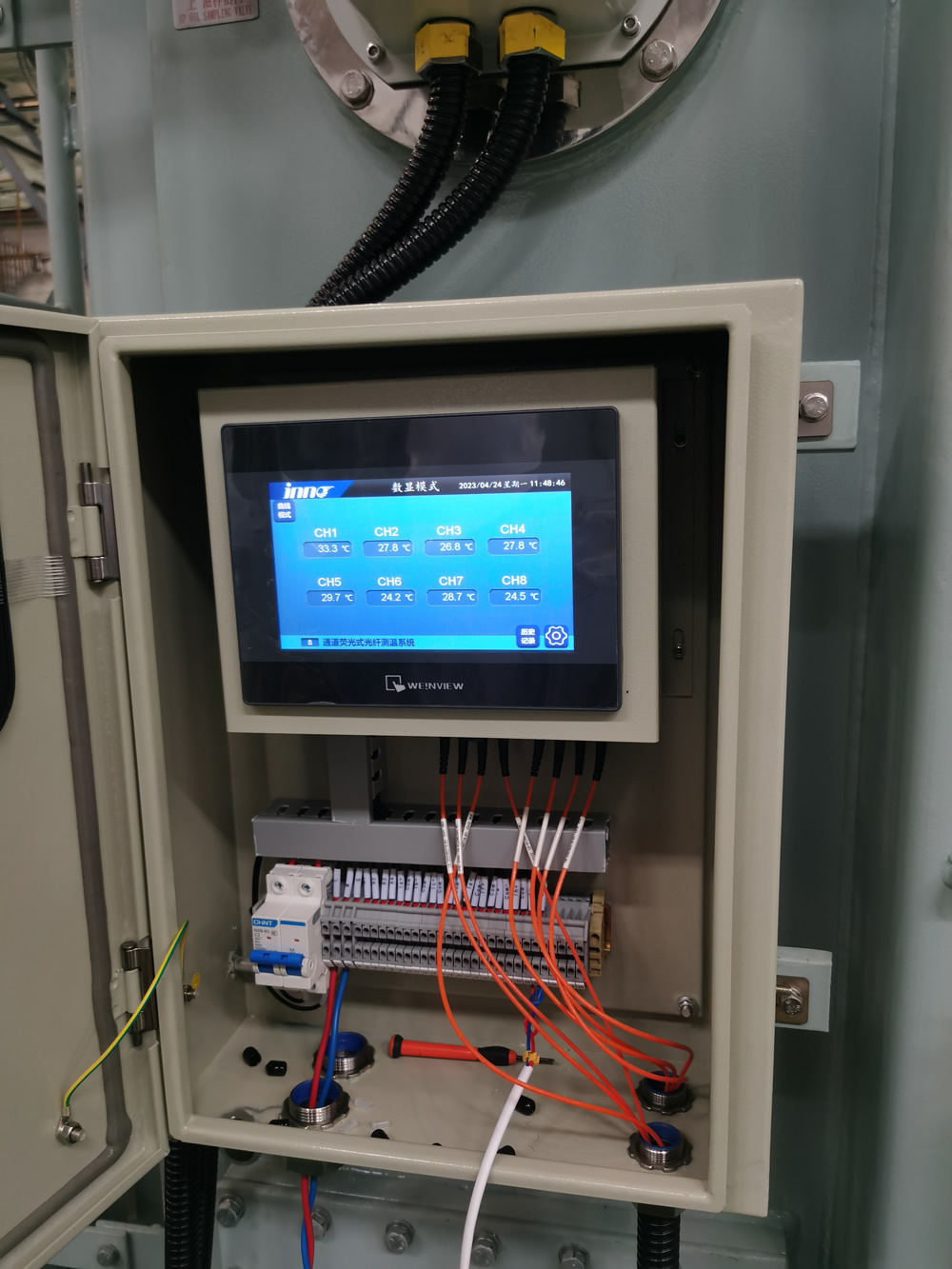
![]()
Fiber optic temperature interrogation system installed in substation ruang kendali, showing rack-mounted equipment, fiber management, and integration with station computer systems.
Melangkah 6: Integrasi dengan Sistem Pemantauan Transformer
To maximize the value of fiber optic temperature data, it must be effectively integrated with broader sistem pemantauan transformator, platform manajemen aset, and operational systems. This integration transforms isolated temperature readings into actionable intelligence.
Data Integration Architectures
Several integration approaches are available, with increasing levels of sophistication:
Basic Data Export
Simplest integration approach for minimal requirements:
- Data Files: Export of temperature data in CSV, XML, or JSON formats.
- Manual Transfer: Scheduled or on-demand data transfers to other systems.
- Basic Visualization: Simple local HMI displays or basic web interfaces.
- Email/SMS Notifications: Direct alerts from the Sistem Pemantauan.
- Standalone Operation: System functions independently with limited external connectivity.
This approach is suitable for isolated installations or where minimal integration is required. It provides core temperature monitoring capabilities with limited analytical functions.
Protocol-Based Integration
Standard industrial protocols for real-time data sharing:
- Modbus TCP/RTU: Widely supported protocol for simple data sharing.
- DNP3: Common in power utility applications with good time-stamping.
- IEC 61850: Advanced standard for substation automation with object modeling.
- OPCUA: Modern protocol with rich data modeling and security.
- MQTT: Lightweight protocol suitable for IIoT applications.
This approach provides real-time data sharing with control systems, SCADA, and other operational platforms. It supports alarm propagation and basic supervisory functions.
Integrasi Perusahaan
Advanced integration with enterprise asset management systems:
- API-Based Integration: RESTful or SOAP APIs for sophisticated data exchange.
- Enterprise Service Bus: Integration through centralized message brokers.
- Data Warehouse Integration: Long-term storage in enterprise historians or data lakes.
- Asset Health Platforms: Dedicated transformer health monitoring systems.
- Pemeliharaan Prediktif Sistem: Integration with AI-driven maintenance platforms.
This approach enables comprehensive asset management, analitik tingkat lanjut, and integration with business processes such as maintenance workflow and asset lifecycle management.
Key Integration Targets
The most valuable systems for temperature data integration include:
Sistem Pemantauan Transformator
Integration with dedicated pemantauan transformator platform:
- Analisis Gas Terlarut (DGA) Sistem: Berkorelasi temperature anomalies with gas generation.
- Pemantauan Semak: Combined analysis of bushing condition and temperature.
- Pemantauan Debit Sebagian: Correlation between temperature and PD activity.
- Load Tap Changer Monitoring: Temperature data related to tap changer operation.
- Pendinginan Pemantauan Sistem: Integrasi with cooling control and monitoring.
This integration provides a comprehensive view of transformer health by correlating temperature with other key diagnostic parameters.
Substation Automation Systems
Integrasi dengan operational control dan pemantauan:
- SCADA Systems: Real-time temperature visibility for operators.
- Protective Relaying: Temperature inputs for thermal protection schemes.
- Manajemen Beban: Temperature data for dynamic loading calculations.
- Kontrol Pendinginan: Intelligent cooling system control based on actual temperatures.
- Manajemen Alarm: Integration with centralized sistem alarm.
This integration supports operational decision-making and automates responses to temperature conditions.
Asset Management Platforms
Integration with enterprise asset management:
- Computerized Maintenance Management Systems (CMMS): Temperature-triggered maintenance.
- Penilaian Kesehatan Aset: Temperature inputs to health indexing algorithms.
- Penilaian Sisa Hidup: Thermal aging calculations based on temperature history.
- Failure Analytics: Pattern recognition for incipient failure detection.
- Manajemen Armada: Comparative analysis across transformer fleet.
This integration supports strategic asset management decisions and optimizes maintenance resources.
Implementation Approaches
Practical steps for successful system integration:
Technical Integration Requirements
- Pemetaan Titik Data: Create detailed mappings between temperature monitoring points and target systems.
- Protocol Converters: Implement appropriate protocol converters or gateways if required.
- Data Quality Management: Implement validation rules to ensure data integrity.
- Sinkronisasi Waktu: Ensure consistent time stamping across integrated systems.
- Bandwidth Requirements: Assess and provision network capacity for data transfer.
- Cybersecurity Measures: Implement appropriate security controls for all integration points.
Data Modeling and Contextualization
- Naming Conventions: Establish consistent naming across systems.
- Asset Hierarchy: Map temperature data to appropriate locations in asset hierarchy.
- Metadata Management: Maintain comprehensive metadata about sensor locations and characteristics.
- Engineering Units: Ensure consistent unit representation across systems.
- Contextual References: Link temperature data to design limits and nameplate information.
Pengujian dan Validasi
- Integration Testing: Verify data flow through all integration points.
- End-to-End Validation: Confirm data accuracy from sensor to final display/storage.
- Performance Testing: Verify system performance under normal and peak data loads.
- Failover Testing: Ensure appropriate behavior during communication failures.
- User Acceptance: Validate that integrated data meets user requirements.
Integration Value Enhancement
Advanced integration creates additional value beyond basic temperature monitoring:
Advanced Analytics and Visualization
- 3D Thermal Mapping: Visual representation of transformer thermal profiles.
- Analisis Tren: Advanced trending with statistical analysis functions.
- Pengenalan Pola: AI-based anomaly detection across multiple parameters.
- Predictive Models: Forecasting of temperature trends based on loading and ambient conditions.
- Comparative Analytics: Benchmarking against similar transformers or historical performance.
Operational Process Integration
- Automated Workflows: Temperature-triggered maintenance workflows.
- Operational Decision Support: Memuat sistem rekomendasi berdasarkan suhu waktu nyata.
- Tanggap darurat: Integrasi dengan sistem manajemen darurat untuk kondisi kritis.
- Pelaporan Kepatuhan: Pembuatan laporan kepatuhan terhadap peraturan secara otomatis.
- Metrik Kinerja: Integrasi dengan pelacakan KPI dan program keunggulan operasional.
Akses Seluler dan Jarak Jauh
- Aplikasi Seluler: Akses smartphone/tablet ke data suhu untuk petugas lapangan.
- Dukungan Pakar Jarak Jauh: Berbagi data secara aman dengan spesialis diagnostik jarak jauh.
- Realitas Tertambah: Hamparan AR data suhu selama inspeksi fisik.
- Alat Kolaborasi: Visualisasi dan analisis bersama untuk tim multi-disiplin.
- Sistem Pemberitahuan: Peringatan yang ditargetkan kepada personel yang tepat berdasarkan kondisi.
![]()
Arsitektur integrasi sistem menunjukkan cara pemantauan suhu serat optik data mengalir ke berbagai sistem perusahaan, menciptakan ekosistem pemantauan kesehatan transformator yang komprehensif.
Melangkah 7: Mengonfigurasi Ambang Batas Alarm dan Sistem Pemberitahuan
Effective alarm configuration transforms continuous temperature monitoring into actionable information that prevents transformer damage and optimizes operation. This requires thoughtful threshold setting, appropriate alarm classification, and effective notification routing.
Establishing Appropriate Temperature Thresholds
Temperature alarm thresholds should be based on transformer desain, standar industri, and operational considerations:
Standards-Based Thresholds
Industry standards provide important reference points for alarm settings:
- IEEE C57.91: Provides guidelines for transformer loading including temperature limits:
- Normal life expectancy loading: 110°C hotspot maximum
- Planned loading beyond nameplate: 120°C hotspot maximum
- Long-time emergency loading: 130°C hotspot maximum
- Short-time emergency loading: 140°C hotspot maximum
- IEC 60076-7: Provides similar guidelines with slight variations for different insulation systems.
- Manufacturer Specifications: Always refer to transformer-specific limits provided by the manufacturer, which may be more conservative than generic standards.
These standards provide the foundation for alarm threshold development but should be adapted to specific transformer characteristics and operational requirements.
Multi-Level Alarm Structure
A graduated alarm structure provides early warning while distinguishing between operational concerns and critical conditions:
| Tingkat Alarm | Typical Setting (Hotspot Berliku) | Tujuan | Tanggapan |
|---|---|---|---|
| Penasihat | 95-100°C | Early indication of elevated temperature | Increased monitoring, evaluate loading if sustained |
| Peringatan | 105-110°C | Approaching standard limits | Evaluate cooling system, consider load reduction |
| Alarm | 120-125°C | Exceeding normal operating limits | Implement load reduction, selidiki penyebabnya |
| Kritis | 135-140°C | Approaching emergency limits | Significant load reduction, prepare contingency plans |
| Keadaan darurat | 150-160°C | Risk of immediate damage | Consider removing from service if not automatically tripped |
These threshold examples should be adjusted based on specific transformer design, sistem isolasi, usia, dan kekritisan. Bagi oil temperature measurements, thresholds would typically be 15-25°C lower than corresponding winding hotspot values.
Rate-of-Change Alarms
Temperature rate-of-change alarms can provide early warning of developing problems:
- Rapid Rise Detection: Typically set for 1-3°C/minute sustained for several minutes, identifying abnormal heating rates not explained by loading.
- Cooling Effectiveness: Alarms based on expected temperature decrease rates when cooling activates.
- Differential Changes: Unusual temperature differences between phases or comparable locations.
- Load-Correlated Changes: Temperature changes disproportionate to load changes.
Rate-of-change alarms are particularly valuable for detecting developing problems before absolute temperature thresholds are reached.
Alarm Classification and Prioritization
Effective alarm management requires appropriate classification and prioritization:
Alarm Priority Classification
- Kritis (Prioritas 1): Conditions requiring immediate operator action to prevent equipment damage or failure.
- Tinggi (Prioritas 2): Abnormal conditions requiring prompt attention and corrective action within a short timeframe.
- Sedang (Prioritas 3): Conditions requiring attention but not immediately threatening to equipment or operation.
- Rendah (Prioritas 4): Advisory information indicating minor deviations or early trends.
This classification should align with broader utility alarm management philosophy and terminology.
Contextual Alarm Processing
Enhancing alarm value through contextual processing:
- Load-Dependent Thresholds: Adjusting alarm thresholds based on current loading conditions.
- Kompensasi Suhu Sekitar: Modifying thresholds based on ambient temperature.
- Operation Mode Context: Different thresholds for different operational states (misalnya, startup, normal operation).
- Alarm Suppression Logic: Preventing alarm floods by suppressing consequential alarms.
- Alarm Shelving: Ability to temporarily suppress known alarms during specific activities.
Contextual processing reduces nuisance alarms and focuses attention on truly significant conditions.
Notification System Configuration
Configure notification systems to ensure the right information reaches the right people:
Notification Methods and Pathways
- Control Room Displays: Integration with operator HMI and sistem manajemen alarm.
- SCADA Alarms: Propagation to central SCADA for operational awareness.
- Mobile Notifications: SMS, e-mail, or push notifications to appropriate personnel.
- Automated Phone Calls: Voice notifications for critical alarms.
- Integration with Enterprise Notification Systems: Leveraging existing corporate emergency notification platforms.
Notification Routing and Escalation
- Role-Based Routing: Directing notifications based on job function and responsibility.
- Time-Based Routing: Different notification paths during business hours versus nights/weekends.
- Acknowledgment Requirements: Tracking acknowledgment of critical notifications.
- Escalation Procedures: Automatic escalation if acknowledgment doesn’t occur within defined timeframes.
- Alarm Response Procedures: Clear documentation of expected actions for each alarm type.
Notification Content Design
- Clear Identification: Unambiguous equipment identification and location.
- Specific Condition: Clear description of the alarm condition and threshold exceeded.
- Severity Indication: Clear indication of alarm priority and urgency.
- Action Guidance: Brief instructions on required response or reference to procedures.
- Contextual Data: Related information such as current load, kondisi sekitar, or relevant trends.
- Informasi Kontak: Additional resources or experts to consult if needed.
Ongoing Alarm Management and Optimization
Alarm systems require regular review and optimization:
Alarm Performance Review
- Alarm Frequency Analysis: Identifying frequently occurring alarms for potential threshold adjustment.
- Nuisance Alarm Identification: Tracking and addressing alarms that do not provide operational value.
- Missed Alarm Analysis: Reviewing incidents to identify potential missed alarm opportunities.
- Response Time Metrics: Tracking time from alarm to acknowledgment and resolution.
- Alarm System Pertunjukan: Regular review of overall alarm system effectiveness.
Proses Perbaikan Berkelanjutan
- Regular Review Meetings: Scheduled reviews of alarm performance with stakeholders.
- Penyempurnaan Ambang Batas: Adjusting thresholds based on operational experience.
- New Alarm Rationalization: Careful evaluation of proposed new alarm points.
- Documentation Updates: Maintaining current alarm philosophy and response documentation.
- Training Reinforcement: Regular refresher training on alarm response procedures.
Advanced Alarm Optimization Techniques
- Analisis Statistik: Using historical data to optimize thresholds.
- Pembelajaran Mesin: Implementing predictive alarming based on pattern recognition.
- State-Based Alarming: Dynamically adjusting alarm configuration based on operating state.
- Alarm Flood Management: Implementing intelligent suppression during major events.
- Human Factors Engineering: Optimizing alarm presentation based on cognitive research.
Alarm configuration interface showing multi-level threshold settings, notification routing, and alarm prioritization for Sistem pemantauan suhu serat optik.
Melangkah 8: Verifikasi dan Komisioning Sistem
Thorough verification and commissioning are essential to confirm that the Sistem pemantauan suhu serat optik is functioning correctly and delivering accurate, data yang dapat diandalkan. This process validates both the physical installation and the data processing chain.
Comprehensive Verification Methodology
A structured approach ensures all system aspects are properly verified:
Physical Installation Verification
- Sensor Placement Confirmation: Verify sensors are installed at intended locations according to documentation.
- Fiber Routing Inspection: Confirm fiber routing follows specified paths with appropriate protection.
- Bend Radius Verification: Check all fiber routes to ensure minimum bend radius requirements are maintained.
- Feedthrough Inspection: Verify proper installation and sealing of tank penetrations.
- External Fiber Protection: Confirm adequate mechanical protection for external fiber runs.
- Connector Inspection: Verify proper connector installation and cleanliness.
Optical Signal Verification
- Continuity Testing: Memeriksa optical continuity for all installed fibers.
- Optical Power Pengukuran Tingkat: Confirm signal levels are within specification for each channel.
- Reflektometri Domain Waktu Optik (OTDR): Melakukan OTDR testing to identify any anomalies in the optical jalur.
- Signal Quality Assessment: Verify signal-to-noise ratio meets system requirements.
- Connection Loss Measurement: Validate connection losses are within acceptable limits.
Measurement Accuracy Verification
- Verifikasi Kalibrasi: Confirm calibration coefficients are correctly applied.
- Reference Comparison: Where possible, compare readings with reference temperature measurements.
- Consistency Checks: Verify consistency between related measurement points.
- Response Testing: Confirm appropriate response to temperature changes when possible.
- Stability Assessment: Verify measurement stability under constant conditions.
System Integration Verification
- Data Flow Confirmation: Verify temperature data correctly flows to all integrated systems.
- Alarm Function Testing: Test each alarm threshold and confirm proper notification.
- Display Verification: Confirm correct representation on all user interfaces.
- Historical Storage Validation: Verify data is properly stored in historical databases.
- Time Synchronization Check: Confirm time stamps are consistent across systems.
Key Commissioning Tests
Specific tests to verify system functionality under various conditions:
Load-Based Response Testing
- Normal Load Response: Document temperature response under normal loading conditions.
- Incremental Loading: Bila memungkinkan, memeriksa temperature response to controlled load increases.
- Cooling Cycle Response: Verify temperature response when cooling systems activate.
- Load Reduction Response: Document cooling rates during controlled load reduction.
- Thermal Time Constants: Calculate heating and cooling time constants for future reference.
Alarm and Notification Testing
- Threshold Triggering: Verify each alarm threshold correctly triggers when conditions are met.
- Notification Delivery: Confirm notifications are delivered to all designated recipients.
- Acknowledgment Functionality: Test alarm acknowledgment and clearing functionality.
- Escalation Testing: Verify alarm escalation occurs according to configuration.
- Audio/Visual Indicators: Confirm proper operation of any local alarm indicators.
Failure Mode Testing
- Power Interruption Response: Verify system behavior and recovery after power loss.
- Communication Failure Handling: Test system response to network communication interruptions.
- Sensor Failure Detection: Confirm detection and alarming for simulated sensor failures when possible.
- Fallback Mode Operation: Verify any redundant or fallback operational modes.
- Data Recovery: Test data backfill or recovery mechanisms after system restoration.
User Function Testing
- Data Retrieval: Verify users can retrieve historical data as required.
- Pembuatan Laporan: Konfirmasikan pengoperasian fungsi pelaporan yang benar.
- Navigasi Antarmuka Pengguna: Uji semua aspek fungsionalitas antarmuka pengguna.
- Fungsi Keamanan: Verifikasi kontrol akses dan mekanisme otentikasi.
- Akses Jarak Jauh: Uji kemampuan akses jarak jauh jika diterapkan.
Dokumentasi Komisioning Komprehensif
Dokumentasi yang menyeluruh menciptakan landasan bagi manajemen sistem jangka panjang:
Dokumentasi yang Dibangun
- Lokasi Sensor Akhir: Dokumentasi terperinci tentang penempatan sensor sebenarnya.
- Diagram Perutean Serat: Representasi akurat dari semua jalur serat.
- Detail Koneksi: Dokumentasi semua titik koneksi dan terminasi.
- Spesifikasi Peralatan: Spesifikasi akhir semua komponen yang terpasang.
- Konfigurasi Perangkat Lunak: Dokumentasi semua pengaturan dan konfigurasi perangkat lunak.
- Arsitektur Integrasi: Penjelasan rinci tentang implementasi integrasi sistem.
Data Kinerja Dasar
- Pembacaan Suhu Awal: Dasar temperature measurements for all sensors.
- Optical Power Levels: Reference measurements for future comparison.
- Signal Quality Metrics: Baseline signal-to-noise ratios and other quality indicators.
- Response Characteristics: Documented thermal response under various conditions.
- Normal Operating Ranges: Expected temperature ranges under typical operation.
Prosedur Operasional
- Panduan Pengguna: Luas operational instructions for system users.
- Alarm Response Procedures: Detailed instructions for responding to each alarm type.
- Troubleshooting Guides: Procedures for diagnosing and addressing common issues.
- Maintenance Procedures: Scheduled maintenance activities and procedures.
- Emergency Procedures: Instructions for system operation during emergency conditions.
Commissioning Report
- Test Results: Comprehensive documentation of all verification and testing results.
- Non-Conformance Documentation: Details of any issues identified and their resolution.
- Sign-Off Records: Formal acceptance documentation from all stakeholders.
- Rekomendasi: Any recommendations for system optimization or enhancement.
- Reference Data: Baseline data for future performance comparison.
System Handover and Training
Ensure smooth transition to operational status through proper handover and training:
Operational Training Program
- System Overview Training: General introduction to system purpose and components.
- Operator Interface Training: Detailed instruction on user interface operation.
- Alarm Response Training: Specific training on alarm interpretation and response.
- Routine Tasks Training: Instruction on regular operational activities.
- Troubleshooting Training: Basic troubleshooting procedures for first-line response.
Maintenance Training Program
- Pemeliharaan Pencegahan: Procedures for scheduled maintenance activities.
- Alat Diagnostik: Training on diagnostic software and tools.
- Penggantian Komponen: Procedures for replacing serviceable components.
- Prosedur Kalibrasi: Training on calibration verification if applicable.
- Advanced Troubleshooting: In-depth troubleshooting for maintenance personnel.
Engineering Training Program
- Arsitektur Sistem: Detailed understanding of system design and integration.
- Analisis Data: Advanced data interpretation and analysis techniques.
- Configuration Management: Procedures for system configuration changes.
- Optimasi Kinerja: Methods for ongoing system optimization.
- Expansion Planning: Considerations for future system expansion.
Formal Handover Process
- Handover Meeting: Formal transfer of system responsibility to operational team.
- Outstanding Items Register: Documentation of any pending items requiring attention.
- Support Contact Establishment: Clear identification of ongoing support resources.
- Warranty Documentation: Formal transfer of all warranty information.
- Performance Acceptance: Agreement on performance metrics for ongoing evaluation.
Engineers performing comprehensive system verification and commissioning tests on newly installed fiber optic temperature monitoring system for power transformer.
Persyaratan Perawatan dan Kalibrasi
Serat optik temperature monitoring systems require significantly less maintenance than conventional measurement sistem, but proper maintenance practices are still essential for long-term reliability and accuracy. A structured approach to maintenance ensures continued system performance throughout the transformer’s life.
Routine Maintenance Activities
Regular maintenance tasks to ensure ongoing system reliability:
Physical System Inspection
- External Fiber Inspection: Annual visual inspection of accessible fiber optic cables for physical damage, menyaring, atau degradasi lingkungan.
- Connector Inspection: Annual inspection of optical connectors for contamination, kerusakan, atau koneksi longgar.
- Feedthrough Examination: Visual inspection of tank penetrations for oil leakage or seal degradation during scheduled transformer inspections.
- Equipment Cabinet Inspection: Quarterly check of interrogation equipment cabinets for cleanliness, environmental controls, and physical security.
- Sensor Junction Inspection: Visual inspection of any accessible sensor junction points during transformer maintenance outages.
Optical System Verification
- Signal Level Verification: Annual verification that optical signal levels for each channel remain within specification.
- Continuity Testing: Annual confirmation of optical continuity for all monitored poin.
- Connection Loss Measurement: Dua tahunan measurement of optical losses at critical connection points to identify degradation.
- OTDR Testing: Biennial OTDR testing of fiber paths to identify any developing anomalies or degradation.
- Communications Interface Check: Annual verification of communication interfaces with integrated systems.
Software and Configuration Maintenance
- Pembaruan Perangkat Lunak: Application of manufacturer-recommended software updates according to utility change management procedures.
- Database Maintenance: Quarterly database maintenance including purging of temporary data and optimization.
- Configuration Backup: Monthly backup of system configuration and settings.
- Security Updates: Timely application of security patches according to cyber security policies.
- User Account Management: Semi-annual review and maintenance of user accounts and access privileges.
Alarm System Maintenance
- Alarm Function Testing: Annual verification of alarm generation and notification pathways.
- Threshold Review: Annual review of alarm thresholds based on operational experience.
- Communication Path Testing: Semi-annual testing of notification delivery to all recipients.
- Alarm Response Review: Annual review of alarm response procedures and updates as needed.
- Nuisance Alarm Analysis: Quarterly review of alarm frequency to identify and address nuisance alarms.
Calibration and Accuracy Verification
Approaches to maintaining measurement accuracy over time:
Inherent Calibration Stability
One of the significant advantages of fiber optic temperature sensors is their inherent long-term stability:
- Fluorescence Decay Systems: These systems typically maintain their calibration for the life of the installation without requiring field recalibration, as the decay time constant is a fundamental physical property that remains stable.
- Sistem Kisi Fiber Bragg: Sensor FBG may require periodic verification due to potential drift in the wavelength-temperature relationship over very long periods.
- Penginderaan Suhu Terdistribusi: sistem DTS biasanya menyertakan fitur kalibrasi mandiri menggunakan bagian referensi serat pada suhu yang diketahui.
Berbeda dengan sensor elektronik konvensional yang biasanya memerlukan kalibrasi ulang tahunan, paling sistem serat optik menjaga akurasi untuk 5-10 tahun atau lebih tanpa penyesuaian.
Metode Verifikasi Akurasi
Meskipun kalibrasi ulang jarang diperlukan, verifikasi akurasi berkala dianjurkan:
- Verifikasi Komparatif: Untuk sensor yang dapat diakses, perbandingan berkala dengan referensi pengukuran suhu menggunakan inframerah yang dikalibrasi atau hubungi termometer.
- Uji Mandiri Sistem: Banyak sistem canggih mencakup fungsi verifikasi bawaan yang memeriksa optik dan kinerja elektronik.
- Poin Referensi yang Diketahui: Beberapa sistem menyertakan sensor referensi pada suhu yang diketahui poin (seperti suhu lingkungan) untuk verifikasi berkelanjutan.
- Analisis Konsistensi: Analisis reguler terkait titik suhu untuk mengidentifikasi sensor apa pun menunjukkan pembacaan anomali.
- Sertifikasi Ulang Pabrik: Bagi aplikasi kritis, manufacturer recertification of interrogation equipment at 3-5 interval tahun.
Verification Frequency Recommendations
| Komponen Sistem | Metode Verifikasi | Recommended Frequency |
|---|---|---|
| Interrogation Equipment | Manufacturer’s verification procedure | 3-5 Tahun |
| Accessible Sensors | Comparative measurement | 2-3 Tahun |
| Internal Sensors | Consistency analysis | Setiap tahun |
| Antarmuka Komunikasi | Validasi data | Setiap tahun |
| Kualitas Sinyal | Optical power measurement | Setiap tahun |
Common Issues and Troubleshooting
Addressing typical issues that may arise in sistem pemantauan suhu serat optik:
Signal Quality Issues
| Gejala | Kemungkinan Penyebabnya | Recommended Actions |
|---|---|---|
| Low Optical Signal Level | Connector contamination, fiber bend, fiber damage | Inspect and clean connectors, check fiber routing, perform OTDR testing |
| Signal Fluctuations | Koneksi longgar, vibration affecting fibers, interference with interrogator | Secure connections, improve fiber strain relief, relocate electronic equipment |
| No Signal | Broken fiber, disconnected sensor, kegagalan peralatan | Verify equipment operation, check connections, perform continuity testing |
| High Noise Level | Interferensi elektromagnetik, equipment issue, poor grounding | Improve shielding, check grounding, memindahkan interogator |
Masalah Akurasi Pengukuran
| Gejala | Kemungkinan Penyebabnya | Recommended Actions |
|---|---|---|
| Offset dalam Bacaan | Penyimpangan kalibrasi, konfigurasi perangkat lunak, perubahan referensi | Verifikasi konfigurasi, periksa nilai referensi, kalibrasi ulang jika perlu |
| Bacaan Tidak menentu | Masalah kualitas sinyal, masalah perangkat lunak, gangguan | Periksa kualitas sinyal, memulai ulang perangkat lunak, mengisolasi sumber interferensi |
| Respon Tertunda | Konfigurasi tingkat pengambilan sampel, masalah komunikasi, penundaan pemrosesan | Sesuaikan tingkat pengambilan sampel, periksa jalur komunikasi, mengoptimalkan pemrosesan |
| Bacaan yang Tidak Konsisten | Degradasi sensor, pemanasan/pendinginan lokal, masalah instalasi | Bandingkan dengan sensor terkait, verifikasi instalasi, memeriksa faktor eksternal |
Masalah Integrasi dan Komunikasi
| Gejala | Kemungkinan Penyebabnya | Recommended Actions |
|---|---|---|
| Data Tidak Mencapai Sistem Terintegrasi | Masalah jaringan, perubahan konfigurasi, ketidakcocokan protokol | Verifikasi konektivitas jaringan, periksa konfigurasi, kompatibilitas protokol uji |
| Alarm Tidak Terpicu | Konfigurasi ambang batas, masalah pemrosesan, kegagalan jalur notifikasi | Verifikasi pengaturan ambang batas, memulai kembali pemrosesan alarm, jalur notifikasi pengujian |
| Pembaruan Data Tertunda | Network congestion, processing bottlenecks, synchronization issues | Analyze network performance, mengoptimalkan pemrosesan, check time synchronization |
| Incorrect Timestamps | Time synchronization failure, configuration issues, software bugs | Verify time server settings, periksa konfigurasi, update software |
Maintenance Documentation and Management
Effective documentation practices ensure proper system maintenance:
Maintenance Records
- Activity Logging: Maintain detailed records of all maintenance activities, findings, and corrective actions.
- Analisis Tren: Review maintenance history to identify recurring issues or degradation patterns.
- Modification Documentation: Maintain comprehensive records of any system modifications or upgrades.
- Calibration Records: Document all verification and calibration activities with results.
- Failure Analysis: Perform and document root cause analysis for any component failures.
Maintenance Management System
- Scheduled Tasks: Implement scheduled maintenance activities in computerized maintenance management system.
- Resource Planning: Schedule appropriate resources and expertise for maintenance activities.
- Manajemen Suku Cadang: Maintain inventory of critical spare components.
- Vendor Coordination: Establish procedures for engaging vendor support when needed.
- Koordinasi Pemadaman: Align maintenance with planned transformer outages when possible.
Perbaikan Berkelanjutan
- Metrik Kinerja: Establish and track reliability and availability metrics for the monitoring system.
- Optimasi Pemeliharaan: Adjust maintenance practices based on operational experience.
- Technology Updates: Stay informed about manufacturer upgrades and enhancements.
- Industry Best Practices: Regularly review and incorporate industry best practices.
- Knowledge Sharing: Establish mechanisms for sharing maintenance learnings across the organization.
Technician performing routine maintenance on Sistem pemantauan suhu serat optik, including signal level verification and optical connector inspection.
Studi Kasus Implementasi Dunia Nyata
Examining successful implementations provides valuable insights into best practices, benefits achieved, and lessons learned from fiber optic temperature monitoring deployments in various transformer aplikasi.
Studi Kasus 1: Large Transmission Utility Fleet-Wide Implementation
Ikhtisar Proyek
A major North American transmission utility implemented fiber optic temperature monitoring across their critical transformer armada, consisting of 87 transformers rated 230kV and above.
- Implementation Period: 3-year phased deployment
- Technology Deployed: Sensor serat optik berbasis fluoresensi
- Titik Pemantauan: 8-12 sensor per transformator, focusing on winding hotspots and critical leads
- Integrasi: Full integration with utility’s asset health management system and SCADA
Pendekatan Implementasi
- Transformer Baru: All new transformer specifications included factory-installed fiber optic temperature sensors.
- Critical Existing Units: Retrofit installation during planned maintenance outages for transformers under 15 tahun.
- Standardized Design: Development of standard sensor configurations by transformer type.
- Phased Rollout: Implementation prioritized based on transformer criticality and condition assessment.
- Training Program: Comprehensive training program for engineering, operasi, and maintenance personnel.
Results and Benefits
- Pencegahan Kegagalan: Early detection of developing hotspots in five transformers, allowing for planned intervention before failure.
- Pemanfaatan Kapasitas: Tercapai 12% average increase in emergency loading capability through precise pemantauan suhu.
- Optimasi Pendinginan: Identified cooling inefficiencies in 22 Transformers, leading to corrective maintenance.
- Maintenance Savings: Reduced overall transformer maintenance costs by 18% melalui pendekatan berbasis kondisi.
- Perpanjangan Hidup: Extended expected service life for 35 transformers by an average of 7 years through improved thermal management.
Lessons Learned
- Standardization Value: Standardizing on a single technology platform significantly reduced training and support requirements.
- Implementation Challenges: Retrofit installations required more careful planning and longer outages than initially estimated.
- Kompleksitas Integrasi: Integration with existing systems required more extensive customization than anticipated.
- Training Importance: Comprehensive training was critical for realizing the full value of the monitoring system.
- ROI Realization: Full return on investment was achieved in 3.2 Tahun, exceeding the initial 4-year projection.
Studi Kasus 2: Industrial Facility Critical Transformer Monitoring
Ikhtisar Proyek
A large aluminum smelting operation implemented advanced temperature monitoring for six critical transformers that directly impacted production capacity.
- Implementation Period: 8-month project
- Technology Deployed: Kisi Fiber Bragg (FBG) multiplexed sensors
- Titik Pemantauan: 18-24 poin per transformator, with comprehensive coverage
- Integrasi: Integration with plant control system and condition monitoring platform
Pendekatan Implementasi
- Pemodelan Termal: Detailed CFD modeling to identify optimal sensor locations based on specific transformer design.
- Custom Installation: Specialized installation during planned production outage with manufacturer support.
- Combined Measurement: Implementation of combined temperature and vibration monitoring using the same FBG infrastructure.
- Analisis Waktu Nyata: Development of custom analytics for production optimization based on transformer capacity.
- Integrasi Operasional: Full integration with production management system for load scheduling.
Results and Benefits
- Production Increase: Tercapai 8.5% increase in production capacity through optimized transformer loading.
- Downtime Reduction: Eliminated two unplanned outages per year previously caused by transformer thermal issues.
- Energy Efficiency: Identified and corrected cooling system issues, reducing cooling energy consumption by 13%.
- Maintenance Impact: Shifted from time-based to condition-based maintenance, mengurangi biaya pemeliharaan secara keseluruhan sebesar 22%.
- Kehidupan Aset: Memperpanjang umur trafo yang diharapkan dari 25 ke 35 years through improved thermal management.
Lessons Learned
- Seleksi Teknologi: FBG teknologi memberikan kemampuan multiplexing yang berharga dan kombinasi pemantauan suhu/getaran.
- Integrasi Proses: Integrasi dengan sistem produksi menciptakan nilai lebih secara signifikan dibandingkan pemantauan mandiri.
- Perencanaan Instalasi: Perencanaan dan latihan yang terperinci meminimalkan dampak produksi selama pemasangan.
- Nilai Analisis: Analisis khusus yang khusus untuk aplikasi menghasilkan keuntungan yang jauh lebih tinggi dibandingkan pemantauan standar.
- Realitas ROI: Proyek mencapai pengembalian dalam waktu kurang dari 14 bulan, terutama melalui peningkatan produksi.
Studi Kasus 3: Pemantauan Transformator Step-Up Pembangkit Listrik
Ikhtisar Proyek
Siklus gabungan 1.200 MW pembangkit listrik menerapkan pemantauan komprehensif untuk empat pembangkit transformator step-up (GSU) yang mewakili potensi titik kegagalan yang kritis.
- Implementation Period: Diimplementasikan selama pemadaman pabrik terjadwal
- Technology Deployed: Hibrida sistem dengan sensor fluoresensi at critical points and distributed sensing for comprehensive coverage
- Titik Pemantauan: 15 discrete sensors plus distributed sensing throughout each transformer
- Integrasi: Full integration with plant DCS and corporate asset management system
Pendekatan Implementasi
- Cakupan Komprehensif: Combined point sensors at known hotspots with distributed sensing for full thermal profiling.
- Dynamic Loading Model: Development of dynamic loading model using real-time temperature data.
- Ambient Compensation: Implementation of ambient temperature compensation for improved accuracy.
- Visualization System: Development of 3D thermal visualization for operations team.
- Analisis Prediktif: Implementation of predictive temperature models based on generation forecasts.
Results and Benefits
- Critical Detection: Identified developing fault in one GSU six months before it would have led to catastrophic failure.
- Peningkatan Ketersediaan: Improved overall plant availability by 0.8% melalui penghapusan kendala terkait transformator.
- Keyakinan Operasional: Mengaktifkan pengoperasian yang mendekati batas trafo selama periode permintaan puncak.
- Dampak Asuransi: Mengurangi premi asuransi melalui pengurangan risiko yang terbukti.
- Penundaan Penggantian: Penggantian tertunda transformator yang sudah tua sebesar 4 tahun melalui peningkatan pemantauan dan pengelolaan.
Lessons Learned
- Kombinasi Teknologi: Pendekatan hibrid yang menggabungkan sensor titik dan penginderaan terdistribusi memberikan cakupan dan presisi yang optimal.
- Dampak Visualisasi: 3Visualisasi D secara signifikan meningkatkan pemahaman dan kepercayaan diri operator.
- Nilai Prediktif: Model prediktif lebih memungkinkan pengelolaan proaktif

Sensor suhu serat optik, Sistem pemantauan cerdas, Produsen serat optik terdistribusi di Cina
 |
 |
 |