 Cảm biến nhiệt độ sợi quang INNO ,hệ thống giám sát nhiệt độ.
Mục lục
- Why Power Transformers Need Fiber Optic Temperature Monitoring
- Key Benefits of Fiber Optic Temperature Monitoring for Transformers
- Understanding Fiber Optic Temperature Sensor Technologies for Transformers
- Bước chân 1: Planning Your Transformer Temperature Monitoring System
- Bước chân 2: Selecting the Right Fiber Optic Temperature Sensors
- Bước chân 3: Determining Optimal Sensor Installation Points
- Bước chân 4: Phương pháp cài đặt và thực tiễn tốt nhất
- Bước chân 5: Setting Up Interrogation Equipment and Data Acquisition
- Bước chân 6: Integration with Transformer Monitoring Systems
- Bước chân 7: Configuring Alarm Thresholds and Notification Systems
- Bước chân 8: System Verification and Commissioning
- Maintenance and Calibration Requirements
- Real-World Implementation Case Studies
- Selecting a Fiber Optic Temperature Sensor Manufacturer
- Câu hỏi thường gặp
Why Power Transformers Need Fiber Optic Temperature Monitoring
Power transformers represent one of the most critical and expensive components in electrical power systems. These vital assets typically cost millions of dollars, with expected service lives of 30-40 năm khi được bảo trì đúng cách. Tuy nhiên, transformer failures can cause catastrophic outages, resulting in significant economic losses and potential safety hazards.
Temperature management is the single most important factor in transformer health and longevity. According to IEEE standards, transformer insulation aging accelerates exponentially with temperature increases—for every 6-8°C rise above rated temperature, insulation life is typically halved. Điều này làm cho chính xác, reliable temperature monitoring essential for optimal transformer operation and maintenance.
The Limitations of Traditional Temperature Monitoring Approaches
Conventional giám sát nhiệt độ máy biến áp methods face significant limitations:
- Chỉ báo nhiệt độ cuộn dây (WTI): These use thermal models to estimate winding temperatures based on top oil measurements và tải hiện tại. Trong khi được sử dụng rộng rãi, they provide only calculated estimates rather than direct measurements, with accuracy typically ±5-10°C under dynamic conditions.
- Máy dò nhiệt độ kháng (RTD): These can only be placed in oil pockets, not directly in windings, creating a significant temperature gradient between measurement point and actual hotspot.
- Nhiệt kế hồng ngoại: Limited to external surface measurements, unable to detect internal hotspots where critical failures typically originate.
- Nhiễu điện từ: Conventional electronic sensors are susceptible to the intense electromagnetic fields present in transformers, dẫn đến measurement errors and potential equipment hư hại.
These limitations often result in conservative loading practices that underutilize transformer capacity, or conversely, undetected hotspots that can lead to premature failures.
The Fiber Optic Temperature Monitoring Solution
Cảm biến nhiệt độ sợi quang technology has emerged as the gold standard for transformer temperature monitoring, providing capabilities that conventional methods simply cannot match:
- Direct Hotspot Measurement: Fiber optic sensors can be embedded directly within transformer windings during manufacturing or retrofit, measuring actual hotspot temperatures rather than estimates.
- Miễn dịch EMI hoàn chỉnh: With no metallic components, đầu dò nhiệt độ sợi quang hoàn toàn miễn nhiễm với nhiễu điện từ, providing reliable readings regardless of transformer loading.
- Độ chính xác cao: Hiện đại hệ thống đo nhiệt độ sợi quang achieve accuracy of ±1°C or better, compared to ±5-10°C for conventional methods under dynamic conditions.
- Khả năng đa điểm: Một đĩa đơn fiber optic temperature monitoring system can measure dozens or even hundreds of points simultaneously, enabling comprehensive thermal mapping of complex transformer geometries.
- Real-Time Data: Continuous monitoring with rapid response times captures transient temperature events that periodic measurements might miss, crucial during overload conditions.
These advantages make cảm biến nhiệt độ sợi quang the preferred solution for critical transformers, particularly in transmission substations, generator step-up applications, and industrial settings where reliability is paramount.
Modern power transformer equipped with fiber optic temperature monitoring system, showing fiber routing and interrogation equipment.
Key Benefits of Fiber Optic Temperature Monitoring for Transformers
Thực hiện fiber optic temperature measurement systems for power transformers delivers multiple tangible benefits that directly impact operational reliability, thực hành bảo trì, asset life, and financial performance.
Extended Transformer Life
Chính xác giám sát nhiệt độ enables operators to prevent damaging thermal events and optimize loading within safe limits:
- Typical transformer life extension of 5-15 years through optimized thermal management
- Early detection of abnormal heating patterns before insulation damage occurs
- Reduced thermal aging rate through more precise loading control
- Historical temperature data enables accurate remaining life assessment
For critical transformers worth millions of dollars, extending service life by even a few years represents substantial financial benefit and deferred capital expenditure.
Increased Loading Capacity
Cuộn dây trực tiếp đo nhiệt độ allows utilities to safely maximize transformer capacity:
- Typical capacity increases of 10-15% compared to conservative loading based on thermal models
- Confidence to utilize short-term emergency ratings during critical periods
- Dynamic loading capability based on actual measured temperatures rather than worst-case assumptions
- Optimized cooling control based on real-time temperature dữ liệu
This increased capacity can defer costly infrastructure upgrades and provide critical flexibility during peak demand periods or contingency situations.
Phát hiện lỗi sớm
Cảm biến nhiệt độ sợi quang can identify developing issues before they progress to catastrophic failures:
- Detection of blocked cooling ducts through localized temperature increases
- Identification of deteriorating electrical connections via abnormal heating patterns
- Early warning of insulation breakdown through hotspot development
- Recognition of cooling system failures through temperature response patterns
Early identification of these issues allows for planned maintenance interventions rather than emergency repairs or replacements after failures occur.
Optimized Maintenance Practices
Comprehensive temperature data enables transition from time-based to condition-based maintenance:
- Prioritization of maintenance based on actual thermal stress history
- Targeted inspections guided by temperature anomalies
- Reduction in unnecessary preventive maintenance activities
- More accurate assessment of transformer health for fleet management
These optimized maintenance practices typically reduce maintenance costs by 15-25% while simultaneously improving reliability and extending asset mạng sống.
Enhanced Safety and Environmental Protection
Preventing transformer thermal failures has significant safety and environmental benefits:
- Reduced risk of catastrophic failures that could result in fires or explosions
- Prevention of oil leaks and spills associated with thermal runaway events
- Enhanced personnel safety through remote monitoring that reduces inspection requirements
- Reduced risk of collateral damage to adjacent equipment during failure events
These benefits are particularly important for transformers located in environmentally sensitive areas or populated locations where safety hazards are heightened.
Comprehensive Documentation and Analytics
Hiện đại hệ thống giám sát nhiệt độ sợi quang provide powerful data management capabilities:
- Complete temperature history for warranty claims and insurance documentation
- Advanced analytics for thermal performance optimization
- Integration with asset health hệ thống quản lý để đánh giá tình trạng toàn diện
- Valuable data for future transformer design and specification improvements
This wealth of data transforms temperature monitoring from a simple protection function to a valuable asset management tool with both operational and strategic benefits.
Lợi tức đầu tư
The financial case for giám sát nhiệt độ sợi quang is compelling. Case studies across utilities worldwide have documented:
- ROI periods typically ranging from 2-4 years for critical transformers
- Failure prevention savings of $500,000 ĐẾN $3 million per avoided major failure (including replacement costs, emergency response, and outage impacts)
- Capacity deferral savings of $1-2 million per substation where transformer upgrades can be postponed through optimized loading
- Maintenance savings of $15,000-$25,000 annually per large transformer through condition-based approaches
These financial benefits make giám sát nhiệt độ sợi quang a sound investment, particularly for large power transformers in critical applications.
Understanding Fiber Optic Temperature Sensor Technologies for Transformers
Before implementing a fiber optic hệ thống giám sát nhiệt độ cho máy biến áp điện, it’s essential to understand the different technologies available and their specific advantages for transformer applications.
Primary Fiber Optic Temperature Sensing Technologies
Two main fiber optic temperature sensor technologies dominate the transformer monitoring chợ, mỗi cái có những đặc điểm riêng biệt:
phân rã huỳnh quang (GaAs) Công nghệ
This technology uses the temperature-dependent fluorescence decay time of gallium arsenide (GaAs) semiconductor material at the tip of an optical fiber:
- Nguyên tắc hoạt động: Khi bị kích thích bởi xung ánh sáng, the GaAs material emits fluorescence with a decay time that precisely correlates to absolute temperature.
- Phạm vi đo: Typically -40°C to +250°C, ideal for transformer applications.
- Sự chính xác: ±0.5°C or better across the measurement range.
- Ưu điểm chính:
- Point-specific measurements with high accuracy
- Absolute temperature measurement requiring no calibration
- Simple installation with minimal fiber handling
- Proven long-term stability in transformer environments
- Hạn chế:
- Each sensing point requires its own fiber
- Limited distributed sensing capability
- Tốt nhất cho: Phê bình giám sát điểm nóng in specific, known locations such as winding hotspots, lối thoát chì, and core joints.
Lưới sợi Bragg (FBG) Công nghệ
Cảm biến FBG use gratings written into the fiber core that reflect specific wavelengths of light based on temperature:
- Nguyên tắc hoạt động: Temperature changes cause the grating period to expand or contract, shifting the wavelength of reflected light proportionally to temperature.
- Phạm vi đo: Typically -40°C to +300°C with specialized fibers và đóng gói.
- Sự chính xác: Typically ±1°C after calibration.
- Ưu điểm chính:
- Multiple sensors (20+ điểm) trên một sợi đơn
- Excellent multiplexing capability for comprehensive monitoring
- Reduced fiber count for complex installations
- Combined temperature and strain sensing capability
- Hạn chế:
- Requires initial calibration and temperature compensation
- More complex signal processing and data interpretation
- Tốt nhất cho: Applications requiring many measurement points, comprehensive thermal mapping, and combined temperature/strain monitoring.
Cảm biến nhiệt độ phân tán (DTS)
DTS systems measure temperature continuously along the entire length of an optical fiber:
- Nguyên tắc hoạt động: Based on Raman or Brillouin backscattering, where the temperature-dependent scattered light is analyzed to determine temperature profiles.
- Phạm vi đo: Typically -40°C to +300°C depending on fiber coating.
- Độ phân giải không gian: 0.5 ĐẾN 2 mét điển hình, với measurement distances lên tới 30km.
- Ưu điểm chính:
- liên tục hồ sơ nhiệt độ dọc theo toàn bộ sợi chiều dài
- No need to predetermine measurement points
- Thousands of effective measurement points with a single fiber
- Ideal for large or complex transformer structures
- Hạn chế:
- Lower spatial resolution compared to point sensors
- Higher cost for interrogation equipment
- More complex installation and data interpretation
- Tốt nhất cho: Large transformers requiring comprehensive thermal mapping, and applications where hotspot locations are not known in advance.
Selecting the Optimal Technology for Your Application
The best technology choice depends on several factors specific to your giám sát máy biến áp yêu cầu:
| Factor | phân rã huỳnh quang (GaAs) | Lưới sợi Bragg (FBG) | Cảm biến phân tán (DTS) |
|---|---|---|---|
| Number of measurement points needed | 1-8 điểm | 8-40 điểm | Continuous profile (thousands of points) |
| Transformer size and complexity | Small to medium | Trung bình đến lớn | Large or complex geometry |
| Installation type | Factory or retrofit | Primarily factory | Factory or surface routing |
| Yêu cầu về độ chính xác | Cao nhất (± 0,5°C) | Cao (±1°C) | Vừa phải (±2°C) |
| Budget considerations | Chi phí thiết bị ban đầu thấp hơn | Moderate system cost | Chi phí thiết bị cao hơn |
| Installation complexity | Simpler | Vừa phải | More complex |
Many utilities implement hybrid approaches, using point sensors (Fluorescence or FBG) for known hotspots and DTS for broader thermal mapping of large transformers. Consulting with experienced nhà sản xuất cảm biến nhiệt độ sợi quang like FJINNO can help determine the optimal technology mix for your specific transformer fleet.

Visual comparison of the three primary cảm biến nhiệt độ sợi quang technologies used in transformer applications, showing sensor design and installation differences.
Bước chân 1: Planning Your Transformer Temperature Monitoring System
Successful implementation of a fiber optic hệ thống giám sát nhiệt độ begins with comprehensive planning that addresses technical requirements, operational goals, and implementation logistics.
Define Monitoring Objectives and Requirements
Begin by clearly establishing what you need to accomplish with your hệ thống giám sát nhiệt độ:
- Primary Goals: Determine whether your focus is on máy biến áp mở rộng mạng sống, increasing loading capacity, improving maintenance practices, or some combination of these objectives.
- Criticality Assessment: Evaluate the strategic importance of the transformer(S) to prioritize implementation and determine appropriate investment levels. Consider factors like:
- Replacement cost and lead time
- Load served and redundancy available
- Historical reliability issues
- Age and condition relative to expected life
- Yêu cầu quy định: Identify any applicable regulatory mandates or standards for temperature monitoring in your jurisdiction.
- Data Integration Needs: Determine how temperature data will integrate with existing asset management, SCADA, or condition hệ thống giám sát.
Documenting these requirements provides the foundation for system specification and guides technology selection quyết định.
Gather Essential Transformer Information
Collect detailed information about the transformer(S) to be monitored:
- Design Documentation: Gather transformer design drawings, particularly winding details and cooling system layouts.
- Temperature Limits: Document specified temperature limits from nameplate or manufacturer documentation:
- Trung bình nhiệt độ cuộn dây tăng lên
- Hotspot temperature rise
- Đứng đầu nhiệt độ dầu tăng lên
- Insulation system thermal class
- Historical Data: Collect any available historical temperature data from existing monitoring systems.
- Loading Profile: Analyze typical loading patterns and identify peak loading periods or seasonal variations.
- Accessibility Information: Document access points, available ports, and physical constraints that may affect installation.
This information is essential for determining optimal sensor placement and establishing appropriate alarm ngưỡng.
Installation Timing Considerations
Determine the optimal timing and approach for installation:
- New Transformer Specification: For new units, cảm biến nhiệt độ sợi quang should be specified during the procurement process and installed during manufacturing for optimal placement within windings.
- Retrofit Options: Đối với máy biến áp hiện có, evaluate retrofit possibilities:
- Planned outage coordination
- Factory refurbishment opportunities
- Non-invasive installation options
- Outage Requirements: Document any operational constraints on outage duration or timing.
- Coordination with Other Work: Identify opportunities to combine lắp đặt cảm biến nhiệt độ with other maintenance or upgrade activities.
Early planning of installation timing can significantly reduce costs and minimize operational impacts.
Budget and Resource Planning
Develop a comprehensive budget and resource plan:
- Thành phần hệ thống: Budget for all system elements:
- Fiber optic temperature sensors and probes
- Sợi quang and feedthroughs
- Signal conditioning and interrogation equipment
- Monitoring software and integration components
- Installation materials and accessories
- Installation Resources: Determine whether installation will be performed by:
- Transformer manufacturer (for new units)
- Chuyên cảm biến sợi quang installation contractors
- In-house technical staff with appropriate training
- Hỗ trợ liên tục: Budget for maintenance, sự định cỡ, và hỗ trợ kỹ thuật.
- Yêu cầu đào tạo: Plan for training of operations and maintenance personnel.
Comprehensive budgeting helps avoid mid-project surprises and ensures all necessary components are accounted for.
Risk Assessment and Mitigation
Identify potential risks and develop mitigation strategies:
- Technical Risks: Compatibility issues, installation challenges, or integration problems.
- Operational Risks: Potential impacts on transformer availability or performance.
- Schedule Risks: Delays in equipment delivery, cài đặt, hoặc vận hành.
- Chiến lược giảm thiểu: Develop specific approaches to address each identified risk.
Proactive risk management increases the likelihood of successful implementation with minimal disruption.
Planning Checklist
Use this checklist to ensure comprehensive planning:
Bước chân 2: Selecting the Right Fiber Optic Temperature Sensors
Choosing the appropriate fiber optic temperature sensors for your transformer application is critical for system performance, độ tin cậy, and long-term value. This selection process should consider both technical capabilities and practical implementation factors.
Key Selection Criteria for Transformer Applications
Evaluate potential cảm biến nhiệt độ sợi quang against these essential criteria:
Temperature Range and Accuracy
Đảm bảo selected sensors meet the specific requirements of transformer ứng dụng:
- Phạm vi hoạt động: Sensors should cover the full temperature range of transformer hoạt động, typically from -40°C to at least +150°C for standard units and up to +180°C for overload conditions.
- Sự chính xác: Look for accuracy of ±1°C or better across the operating range, particularly at critical temperature thresholds around 110-140°C where thermal aging accelerates.
- Nghị quyết: 0.1°C resolution is typically required for trend analysis and subtle anomaly detection.
- Sự ổn định: Long-term stability with minimal drift over years of operation is essential for transformer lifetime monitoring.
Độ bền môi trường
Transformer environments are demanding, requiring sensors designed for harsh conditions:
- Khả năng tương thích dầu: Sensors must be compatible with transformer dầu khoáng, natural ester fluids, or synthetic insulating fluids without degradation over decades.
- Kháng hóa chất: Must withstand exposure to dầu biến thế additives, khí hòa tan, and aging byproducts.
- Độ bền điện môi: All materials must maintain appropriate dielectric properties in high-voltage environments.
- Mechanical Durability: Must withstand vibration, đạp xe nhiệt, and physical stresses within the transformer.
- Expected Lifetime: Sensor lifetime should match or exceed the remaining transformer life, tiêu biểu 25+ năm.
Installation and Integration Considerations
Practical implementation factors significantly impact system success:
- Yếu tố hình thức: Sensor size and shape must be compatible with available installation spaces within the transformer.
- Phương pháp cài đặt: Consider whether sensors will be factory-installed during construction or retrofitted to existing units.
- Feedthrough Options: Evaluate tank wall penetration options that maintain oil seal integrity and dielectric strength.
- Fiber Management: Consider fiber routing, bend radius limitations, and protection methods both inside and outside the transformer.
- Connectivity: Ensure compatibility with selected interrogation equipment and availability of appropriate connectors.
Chứng nhận và tuân thủ tiêu chuẩn
Verify that sensors meet relevant industry standards and certifications:
- Tiêu chuẩn IEEE: Compliance with IEEE C57.91 for transformer loading and temperature monitoring.
- Tiêu chuẩn IEC: Adherence to relevant IEC standards for transformer monitoring and thiết bị điện.
- Material Safety: Certification that all materials are compatible with transformer insulating systems.
- Đảm bảo chất lượng: ISO 9001 certification for manufacturing processes.
- Hazardous Location: Appropriate certifications if installed in classified hazardous locations.
Support and Documentation
Comprehensive support is essential for successful long-term implementation:
- Installation Documentation: Detailed installation guidelines specific to transformer applications.
- Giấy chứng nhận hiệu chuẩn: Individual calibration data and traceability for each sensor.
- Hỗ trợ kỹ thuật: Availability of expert technical support for installation and troubleshooting.
- Warranty Terms: Comprehensive warranty appropriate for long-life transformer applications.
- Repair/Replacement Options: Clear procedures for addressing any sensor issues that may arise.
Comparison of Leading Fiber Optic Temperature Sensor Options for Transformers
The table below compares key specifications of fiber optic temperature sensors commonly used in transformer applications:
| Đặc điểm kỹ thuật | Standard Transformer Sensor | Nhiệt độ cao Sensor | Retrofit Solution |
|---|---|---|---|
| Phạm vi nhiệt độ | -40°C đến +200°C | -40°C đến +300°C | -40°C đến +180°C |
| Sự chính xác | ± 0,5°C | ±1,0°C | ±1,0°C |
| Thời gian đáp ứng | < 1 thứ hai | < 1 thứ hai | 1-2 giây |
| Đường kính cảm biến | 0.8 – 1.2 mm | 1.2 – 2.0 mm | 2.0 – 3.0 mm |
| Cài đặt điển hình | Factory integrated | Factory integrated | Field retrofit |
| Expected Lifetime | 25+ năm | 25+ năm | 20+ năm |
| Ứng dụng tối ưu | Mới máy biến áp điện | High-temperature designs | Existing transformers |
Selection should be based on your specific loại máy biến áp, installation approach, và mục tiêu giám sát. Nhà sản xuất hàng đầu like FJINNO offer specialized selection guidance based on your particular application requirements.
Practical Selection Recommendations
Based on industry experience, these practical recommendations can help guide your selection quá trình:
- For New Transformers: Specify factory-installed sensors with direct winding integration for optimal performance. Include detailed sensor specifications in transformer procurement documents.
- For Retrofit Projects: Consider non-invasive solutions that can be installed during planned outages without major transformer modifications. Magnetic or adhesive mounting options can provide valuable data without requiring internal access.
- For Critical Assets: Implement redundant sensors at key measurement points to ensure continuous monitoring even if individual sensors experience issues.
- For Fleet-Wide Deployment: Standardize on a single sensor technology platform to simplify maintenance, spare parts management, và đào tạo nhân viên.
- For Integration with Existing Systems: Verify compatibility with your current monitoring platforms before finalizing sensor selection to avoid integration challenges.
Working with experienced nhà sản xuất who specialize in transformer applications can significantly simplify the selection process and ensure optimal system performance.

Khác biệt types of fiber optic temperature sensors optimized for transformer ứng dụng, showing various form factors for factory installation and retrofit scenarios.
Bước chân 3: Determining Optimal Sensor Installation Points
Strategic placement of fiber optic temperature sensors is critical for effective transformer monitoring. The goal is to place sensors at locations that provide the most valuable thermal information while remaining physically accessible for installation.
Primary Temperature Monitoring Locations
These locations represent the most important monitoring points in power transformers:
Winding Hotspot Locations
The most critical measurement points are the winding hotspots, where the highest temperatures typically occur:
- Top Disc/Turn of Each Phase: Tiêu biểu 2/3 up from the bottom in the highest current density portion of each winding.
- Last Turn of Each Winding: Where the winding exits to the lead, often a location of elevated temperature.
- Areas of Restricted Oil Flow: Locations where cooling duct spacing is reduced or flow is restricted.
- Multiple Radial Positions: For large windings, sensors at different radial positions provide valuable temperature gradient information.
Winding hotspot monitoring provides the most valuable data for thermal management and life assessment. For transformers with complex winding arrangements, thermal modeling during design can identify the most critical hotspot locations.
Lead Exit Points
Lead connections and exit points often experience elevated temperatures:
- Turret Connections: Where windings connect to bushings or lead exits.
- Tap Changer Connections: Connections to the tap changer selector, particularly at extreme tap positions.
- High-Current Joints: Any connection points carrying full winding current.
- Lead Insulation: Areas where lead insulation may restrict cooling oil flow.
These locations are particularly valuable for early detection of connection problems that can lead to catastrophic failures if left undetected.
Oil Temperature Monitoring Points
Chiến lược oil temperature measurements provide context for winding nhiệt độ:
- Top Oil: Near the top of the tank, typically near the radiator return.
- Bottom Oil: At the coolest point, typically near the radiator supply.
- Cooling Equipment Entry/Exit: At radiator or cooler inlet and outlet.
- Oil Flow Channels: In major oil flow paths within the winding structure.
Oil temperature measurements complement winding dữ liệu nhiệt độ, providing insights into cooling system performance and overall thermal behavior.
Thành phần cốt lõi và kết cấu
Monitoring key structural elements can identify specific failure modes:
- Core Joints: Particularly at multistep lap joints where eddy current heating may occur.
- Core Clamping Structures: Areas where stray flux may induce heating in metallic components.
- Magnetic Shunts: Components designed to control flux paths that may experience heating.
- Tank Walls: Areas near high-current components where eddy currents may cause localized heating.
These measurements can identify issues not revealed by conventional monitoring, such as core problems or stray flux heating.
Determining the Optimal Number of Sensors
The appropriate number of giám sát nhiệt độ points depends on several factors:
| Loại máy biến áp | Minimum Recommended | Comprehensive Monitoring | Key Locations |
|---|---|---|---|
| Máy biến áp phân phối (<10 MVA) |
3-5 cảm biến | 6-10 cảm biến | Dầu hàng đầu, one hotspot per phase |
| Máy biến áp công suất trung bình (10-100 MVA) |
6-9 cảm biến | 12-18 cảm biến | Top/bottom oil, two hotspots per phase, key leads |
| Máy biến áp điện lớn (>100 MVA) |
9-12 cảm biến | 20-30 cảm biến | Multiple points per phase, all leads, đường dẫn dầu |
| Tăng cường máy phát điện Máy biến áp |
12-15 cảm biến | 24-36 cảm biến | Dense coverage of all critical areas due to high importance |
| HVDC Converter Máy biến áp |
15-20 cảm biến | 30-40 cảm biến | Additional focus on valve windings and areas exposed to harmonics |
These recommendations should be adjusted based on specific transformer design, sự quan trọng, tải mẫu, và hạn chế về ngân sách. Đối với máy biến áp quan trọng, more comprehensive monitoring provides greater diagnostic capability and risk reduction.
Sensor Placement Strategies Based on Installation Type
Installation constraints significantly influence optimal sensor placement:
Factory Installation (New Transformers)
For new transformers with sensors installed during manufacturing:
- Direct Winding Integration: Sensors can be embedded directly between disc windings or within the conductor insulation.
- Lead Embedding: Sensors can be integrated within lead insulation structures.
- Custom Routing: Cáp quang can be routed through dedicated paths with appropriate protection.
- Optimal Placement: Working with the transformer manufacturer allows placement at the theoretical hotspot locations identified during design.
Factory installation offers the most comprehensive monitoring capability with optimal sensor placement. Detailed placement instructions should be included in transformer specifications.
Cài đặt trang bị thêm (Existing Transformers)
For existing transformers requiring non-invasive or minimally invasive approaches:
- Oil Pocket Sensors: Utilize existing thermometer wells and oil pockets where available.
- External Surface Monitoring: Strategic placement on tank walls near expected internal hotspots.
- Bushing Collar Sensors: Placement at bushing collars to monitor lead exit areas.
- Limited Internal Access: When transformer is opened for maintenance, limited sensor installation may be possible at accessible locations.
While retrofit installations typically cannot access the true winding hotspots, strategically placed sensors still provide valuable information beyond conventional monitoring systems.
Factory Refurbishment Opportunities
When transformers undergo factory refurbishment or repair:
- Partial Winding Access: During rewind operations, sensors can be installed in critical winding sections.
- Lead Replacement: When leads are replaced or repaired, sensors can be integrated into the new insulation.
- Cooling Modification: During cooling system upgrades, additional access for sensor placement may be available.
- Internal Inspection: Even without major work, internal inspection outages may allow limited sensor placement.
Factory refurbishment represents an excellent opportunity for comprehensive sensor installation in existing transformers, combining the benefits of factory precision with extended monitoring of aging assets.
Documenting Sensor Placement
Thorough documentation of sensor placement is essential for data interpretation and future reference:
- Detailed Placement Diagrams: Create detailed drawings showing exact sensor locations with references to transformer design coordinates.
- Sensor Identification System: Implement a clear naming convention that identifies the location and function of each sensor.
- Photographs: Khi có thể, document installation with photographs before components are assembled.
- Bản ghi được xây dựng: Update documentation to reflect any changes made during actual installation.
- Digital Records: Maintain electronic records accessible to maintenance and engineering personnel.
This documentation is invaluable for interpreting temperature data, khắc phục sự cố, and planning future monitoring enhancements.

Cross-sectional diagram of a power transformer showing optimal fiber optic temperature sensor placement locations for comprehensive thermal monitoring.
Bước chân 4: Phương pháp cài đặt và thực tiễn tốt nhất
Việc lắp đặt đúng cách fiber optic temperature sensors is critical for accurate measurement, độ tin cậy lâu dài, and transformer integrity. Different approaches are required depending on whether installation occurs during manufacturing or as a retrofit to existing units.
Factory Installation During Manufacturing
Đang cài đặt sensors during transformer manufacturing offers optimal placement and integration:
Winding Integration Process
For direct integration into cuộn dây máy biến áp:
- Coordination with Manufacturer: Provide detailed installation specifications to the transformer manufacturer during the design phase.
- Sensor Preparation: Sensors should be pre-tested and calibration-verified before installation begins.
- Positioning During Winding: As disc windings are constructed, sensors are positioned at predetermined locations between discs or within the conductor insulation.
- Secure Attachment: Sensors must be securely attached without damaging insulation or restricting oil flow.
- Fiber Routing: Optical fibers are carefully routed through the winding structure with proper bend radius management and abrasion protection.
- Strain Relief: Adequate strain relief must be provided to prevent tension on sensors during thermal cycling and winding movement.
- Protection During Assembly: Fibers must be protected during subsequent assembly operations to prevent damage.
This process requires close collaboration between the sensor supplier and transformer manufacturer to ensure proper installation without compromising transformer design or performance.
Lead and Structural Integration
For monitoring leads, kết nối, và các thành phần cấu trúc:
- Lead Integration: Sensors are incorporated within the lead insulation structure during lead fabrication.
- Điểm kết nối: Sensors are positioned at critical connection points between windings and leads.
- Thành phần cốt lõi: Sensors are attached to core laminations or clamping structures at predetermined locations.
- Oil Flow Paths: Sensors are positioned within major oil flow channels to monitor hiệu quả làm mát.
- Tank Wall Mounting: Internal sensors may be mounted to tank walls at locations where external hotspots are anticipated.
These locations often provide valuable diagnostic information beyond the primary winding hotspots.
Fiber Management and Feedthrough
Proper management of optical fibers from internal sensors to external equipment:
- Fiber Bundling: Individual fibers are bundled and protected within suitable tubing or conduit.
- Routing Path: Fibers are routed to avoid areas of mechanical stress, điện trường cao, or physical hazards.
- Tank Penetration: Specialized oil-tight optical feedthroughs are installed in the transformer tank wall.
- Feedthrough Types:
- Epoxy-sealed multi-fiber penetrations
- Individual fiber compression fittings
- Pre-assembled multi-channel feedthroughs
- External Protection: Outside the tank, fibers are protected within appropriate conduit to the monitoring equipment.
- Connector Termination: Fibers are terminated with appropriate optical connectors for connection to interrogation equipment.
The tank penetration must maintain oil seal integrity while providing reliable optical transmission for decades of service.
Retrofit Installation for Existing Transformers
Installing monitoring on existing transformers requires different approaches:
External Surface Mounting
Non-invasive monitoring using external sensors:
- Mô hình nhiệt: Computational fluid dynamics (CFD) modeling to identify external locations corresponding to internal hotspots.
- Surface Preparation: Careful cleaning and preparation of mounting surfaces.
- Sensor Attachment: Using appropriate adhesives, magnetic mounts, or mechanical attachments.
- Thermal Contact: Ensuring good thermal contact with tank surface using thermal compounds if necessary.
- Bảo vệ môi trường: Providing weather protection and UV shielding for exposed components.
- Correlation Factors: Developing correlation factors between external measurements and estimated internal temperatures.
While not as accurate as direct internal measurements, bên ngoài sensors provide valuable trending information without requiring transformer opening.
Oil Pocket Integration
Utilizing existing thermowell and oil access points:
- Access Point Inventory: Identifying available thermometer wells, sampling ports, and other access points.
- Custom Probe Design: Designing probes to fit existing openings while maintaining oil seals.
- Sealing Solutions: Implementing appropriate sealing methods to prevent oil leaks.
- Depth Adjustment: Định vị sensors at optimal measurement depths within oil.
- Retrofitting Valves: Trong một số trường hợp, installing specialized valves that allow sensor insertion without draining oil.
This approach provides direct oil temperature measurement without major transformer modifications.
Limited Internal Access During Maintenance
Installing sensors during scheduled internal inspections:
- Maintenance Coordination: Planning sensor installation to coincide with scheduled internal inspections or repairs.
- Accessible Locations: Identifying winding, lead, and structural locations accessible during partial disassembly.
- Limited Winding Access: Installing sensors on outer winding surfaces or accessible lead connections.
- Quick-Connect Systems: Using specialized quick-connect fiber optic systems to minimize installation thời gian.
- Tài liệu: Thorough documentation of installed locations for future reference.
This approach provides a compromise between optimal placement and minimal outage impact.
Critical Installation Best Practices
Regardless of installation method, these best practices should be followed:
Quản lý cáp quang
- Minimum Bend Radius: Maintain manufacturer-specified minimum bend radius (typically 30mm or greater) at all points.
- Strain Relief: Provide adequate strain relief at all transition points and connections.
- Protection from Abrasion: Use appropriate tubing or conduit to protect fibers from abrasion.
- Expansion Loops: Include service loops to accommodate thermal expansion and mechanical movement.
- Clear Identification: Implement clear fiber identification and labeling systems.
Electrical and Dielectric Considerations
- Maintain Dielectric Strength: Ensure sensor installation does not compromise insulation systems.
- Clearance Distances: Maintain appropriate clearances to energized components.
- Electric Field Management: Avoid creating high electric field concentration points.
- Grounding Considerations: Ensure proper grounding of any metallic components.
Oil System Integrity
- Phòng chống rò rỉ dầu: Ensure all penetrations and fittings maintain oil-tight seals.
- Moisture Prevention: Minimize exposure time during installation to prevent moisture ingress.
- Material Compatibility: Use only materials compatible with transformer insulating fluid.
- Cooling Flow: Avoid obstructing oil flow paths or cooling ducts.
Documentation and Verification
- Installation Records: Maintain detailed records of all installation steps and sensor locations.
- Photographic Documentation: Take photographs during installation when possible.
- Continuity Testing: Verify optical continuity before and after each installation step.
- Final Verification: Conduct comprehensive system verification before returning transformer to service.
Pre-Installation and Installation Checklists
Use these checklists to ensure thorough preparation and execution:
Danh sách kiểm tra trước khi cài đặt
Installation Execution Checklist
Cài đặt fiber optic temperature sensors during transformer manufacturing, showing careful placement between winding discs and proper fiber routing.
Bước chân 5: Setting Up Interrogation Equipment and Data Acquisition
các cảm biến nhiệt độ sợi quang installed in transformers must connect to appropriate interrogation equipment that converts optical signals into temperature measurements. Properly setting up this equipment is essential for accurate, reliable monitoring.
Selecting Appropriate Interrogation Equipment
The interrogation system must match your sensor technology and monitoring yêu cầu:
Fluorescence Decay Systems
For GaAs or similar fluorescence-based sensors:
- Số kênh: Select systems with appropriate channel capacity for your sensor deployment (tiêu biểu 4, 8, hoặc 16 kênh).
- Measurement Speed: Consider update rate requirements, tiêu biểu 1-10 seconds per channel is sufficient for giám sát máy biến áp.
- Accuracy Specifications: Verify system accuracy meets or exceeds ±1°C across the operating range.
- Optical Power: Ensure sufficient optical power for the fiber lengths deployed.
- Connector Types: Confirm compatibility with your selected sensor connectors (typically ST or FC).
Fiber Bragg Grating Systems
For FBG-based sensor networks:
- Wavelength Range: Must accommodate all FBG sensors in your network with appropriate wavelength spacing.
- Nghị quyết: Tiêu biểu 1-5 pm wavelength resolution for accurate đo nhiệt độ.
- Scanning Speed: Consider speed requirements for your application, especially if strain measurements are also included.
- Khả năng ghép kênh: Ensure support for your channel and sensor count per fiber.
- Bù nhiệt độ: Verify capability to compensate for strain effects in combined sensing applications.
Hệ thống cảm biến nhiệt độ phân tán
For DTS installations:
- Độ phân giải không gian: Typically 0.5m to 2m resolution is appropriate for transformer applications.
- Phạm vi khoảng cách: Must support your total fiber length with adequate signal-to-noise ratio.
- Độ phân giải nhiệt độ: Verify system provides required temperature resolution (typically 0.1°C).
- Thời gian đo: Consider trade-offs between measurement time and temperature nghị quyết.
- Loại sợi Khả năng tương thích: Ensure compatibility with your installed fiber type (multimode/single-mode).
Interrogator Installation and Environment
Proper installation of interrogation equipment đảm bảo đáng tin cậy hoạt động:
Physical Installation Requirements
- Location Selection: Identify an appropriate location considering:
- Maximum fiber distance limitations (typically 100-500m depending on technology)
- Điều kiện môi trường (nhiệt độ, độ ẩm, bụi)
- Accessibility for maintenance
- Security considerations
- Mounting Options:
- Rack mounting in control buildings
- Wall mounting in suitable enclosures
- Free-standing cabinets with climate control
- DIN rail mounting for smaller units
- Environment Control:
- Maintain temperature within equipment specifications (typically 10-40°C)
- Control humidity to prevent condensation
- Provide dust filtration if necessary
- Consider solar shielding for outdoor installations
Power and Communication Requirements
- Nguồn điện:
- Verify voltage requirements (typically 100-240VAC or 24VDC)
- Provide uninterruptible power supply (UPS) vì ứng dụng quan trọng
- Implement appropriate surge protection
- Consider power consumption for proper circuit sizing
- Network Connectivity:
- Provide Ethernet connection to facility network
- Configure appropriate IP addressing and security
- Consider redundant communication paths for critical systems
- Implementation of appropriate cybersecurity measures
- Serial Communications:
- RS-232/485 connections for legacy systems if required
- Modbus or DNP3 connectivity for SCADA integration
- Appropriate converters for protocol translation if needed
Data Acquisition and Storage Configuration
Configure the system for appropriate data collection and storage:
Sampling Rate and Data Storage
- Khoảng thời gian đo: Configure appropriate measurement intervals:
- Hoạt động bình thường: Tiêu biểu 1-5 minutes is sufficient
- Dynamic conditions: More frequent sampling during load changes
- Alarm conditions: Increased sampling when thresholds are approached
- Data Storage Requirements:
- Raw data storage period (tiêu biểu 30-90 ngày)
- Aggregated data storage (tiêu biểu 1-5 năm)
- Storage capacity planning for expected data volumes
- Database type selection (time-series databases preferred)
- Data Compression:
- Consider deadband recording to reduce storage requirements
- Implement appropriate compression algorithms
- Balance storage efficiency with data resolution needs
Data Backup and Redundancy
- Backup Procedures:
- Automated backup scheduling
- Off-site or cloud backup options
- Backup verification procedures
- Tùy chọn dự phòng:
- Local redundant storage
- RAID configurations for critical databases
- Redundant servers for high-availability applications
- Recovery Planning:
- Documented recovery procedures
- Regular recovery testing
- Maximum acceptable data loss determination
Initial System Configuration and Testing
Proper initial setup ensures accurate measurement and reliable hoạt động:
Sensor Configuration
- Sensor Registration: Configure each sensor in the system with:
- Unique identifier aligned with installation documentation
- Physical location description
- Sensor type and calibration parameters
- Measurement range and limits
- Xác minh hiệu chuẩn:
- Apply factory calibration coefficients
- Verify calibration with known temperature reference if applicable
- Document baseline readings for future comparison
- Signal Quality Verification:
- Check optical power levels for each channel
- Verify signal-to-noise ratios meet specifications
- Document baseline optical parameters
Kiểm tra hệ thống
- Kiểm tra chức năng:
- Verify readings from all sensors
- Confirm expected temperature relationships
- Test response to simulated temperature changes if possible
- Kiểm tra truyền thông:
- Verify data export to integrated systems
- Test network connectivity and remote access
- Confirm alarm transmission pathways
- Failure Mode Testing:
- Xác minh system response to power interruption
- Test fiber break detection if supported
- Validate system recovery after simulated failures
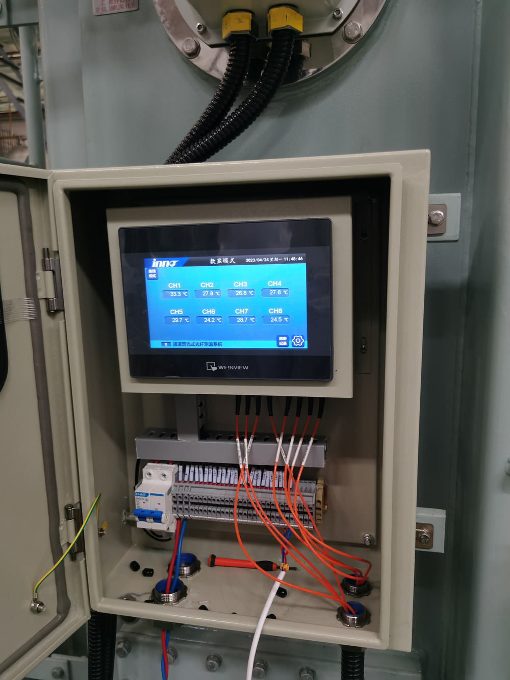
![]()
Fiber optic temperature interrogation system installed in substation phòng điều khiển, showing rack-mounted equipment, fiber management, and integration with station computer systems.
Bước chân 6: Integration with Transformer Monitoring Systems
To maximize the value of fiber optic temperature data, it must be effectively integrated with broader hệ thống giám sát máy biến áp, nền tảng quản lý tài sản, and operational systems. This integration transforms isolated temperature readings into actionable intelligence.
Data Integration Architectures
Several integration approaches are available, with increasing levels of sophistication:
Basic Data Export
Simplest integration approach for minimal requirements:
- Data Files: Export of temperature data in CSV, XML, or JSON formats.
- Manual Transfer: Scheduled or on-demand data transfers to other systems.
- Basic Visualization: Simple local HMI displays or basic web interfaces.
- Email/SMS Notifications: Direct alerts from the hệ thống giám sát.
- Standalone Operation: System functions independently with limited external connectivity.
This approach is suitable for isolated installations or where minimal integration is required. It provides core temperature monitoring capabilities with limited analytical functions.
Protocol-Based Integration
Standard industrial protocols for real-time data sharing:
- Modbus TCP/RTU: Widely supported protocol for simple data sharing.
- DNP3: Common in power utility applications with good time-stamping.
- IEC 61850: Advanced standard for substation automation with object modeling.
- OPC UA: Modern protocol with rich data modeling and security.
- MQTT: Lightweight protocol suitable for IIoT applications.
This approach provides real-time data sharing with control systems, SCADA, and other operational platforms. It supports alarm propagation and basic supervisory functions.
Tích hợp doanh nghiệp
Advanced integration with enterprise asset management systems:
- API-Based Integration: RESTful or SOAP APIs for sophisticated data exchange.
- Enterprise Service Bus: Integration through centralized message brokers.
- Data Warehouse Integration: Long-term storage in enterprise historians or data lakes.
- Asset Health Platforms: Dedicated transformer health monitoring systems.
- Bảo trì dự đoán Hệ thống: Integration with AI-driven maintenance platforms.
This approach enables comprehensive asset management, phân tích nâng cao, and integration with business processes such as maintenance workflow and asset lifecycle management.
Key Integration Targets
The most valuable systems for temperature data integration include:
Hệ thống giám sát máy biến áp
Integration with dedicated giám sát máy biến áp nền tảng:
- Phân tích khí hòa tan (DGA) Hệ thống: Correlating temperature anomalies with gas generation.
- Giám sát ống lót: Combined analysis of bushing condition and temperature.
- Giám sát phóng điện một phần: Correlation between temperature and PD activity.
- Load Tap Changer Monitoring: Temperature data related to tap changer operation.
- làm mát System Monitoring: Tích hợp with cooling control and monitoring.
This integration provides a comprehensive view of transformer health by correlating temperature with other key diagnostic parameters.
Substation Automation Systems
Tích hợp với operational control và giám sát:
- SCADA Systems: Real-time temperature visibility for operators.
- Protective Relaying: Temperature inputs for thermal protection schemes.
- Quản lý tải: Temperature data for dynamic loading calculations.
- Cooling Control: Intelligent cooling system control based on actual temperatures.
- Quản lý cảnh báo: Integration with centralized hệ thống báo động.
This integration supports operational decision-making and automates responses to temperature conditions.
Asset Management Platforms
Integration with enterprise asset management:
- Computerized Maintenance Management Systems (CMMS): Temperature-triggered maintenance.
- Chấm điểm tình trạng tài sản: Temperature inputs to health indexing algorithms.
- Remaining Life Assessment: Thermal aging calculations based on temperature history.
- Failure Analytics: Pattern recognition for incipient failure detection.
- Quản lý đội tàu: Comparative analysis across transformer fleet.
This integration supports strategic asset management decisions and optimizes maintenance resources.
Phương pháp thực hiện
Practical steps for successful system integration:
Technical Integration Requirements
- Data Point Mapping: Create detailed mappings between temperature monitoring points and target systems.
- Protocol Converters: Implement appropriate protocol converters or gateways if required.
- Data Quality Management: Implement validation rules to ensure data integrity.
- Đồng bộ hóa thời gian: Ensure consistent time stamping across integrated systems.
- Bandwidth Requirements: Assess and provision network capacity for data transfer.
- Cybersecurity Measures: Implement appropriate security controls for all integration points.
Data Modeling and Contextualization
- Naming Conventions: Establish consistent naming across systems.
- Asset Hierarchy: Map temperature data to appropriate locations in asset hierarchy.
- Metadata Management: Maintain comprehensive metadata about sensor locations and characteristics.
- Engineering Units: Ensure consistent unit representation across systems.
- Contextual References: Link temperature data to design limits and nameplate information.
Testing and Validation
- Integration Testing: Verify data flow through all integration points.
- End-to-End Validation: Confirm data accuracy from sensor to final display/storage.
- Performance Testing: Verify system performance under normal and peak data loads.
- Failover Testing: Ensure appropriate behavior during communication failures.
- User Acceptance: Validate that integrated data meets user requirements.
Integration Value Enhancement
Advanced integration creates additional value beyond basic temperature monitoring:
Advanced Analytics and Visualization
- 3D Thermal Mapping: Visual representation of transformer thermal profiles.
- Phân tích xu hướng: Advanced trending with statistical analysis functions.
- Nhận dạng mẫu: AI-based anomaly detection across multiple parameters.
- Predictive Models: Forecasting of temperature trends based on loading and ambient conditions.
- Comparative Analytics: Benchmarking against similar transformers or historical performance.
Operational Process Integration
- Automated Workflows: Temperature-triggered maintenance workflows.
- Operational Decision Support: Loading recommendation systems based on real-time temperature.
- Emergency Response: Integration with emergency management systems for critical conditions.
- Compliance Reporting: Automated generation of regulatory compliance reports.
- Performance Metrics: Integration with KPI tracking and operational excellence programs.
Mobile and Remote Access
- Ứng dụng di động: Smartphone/tablet access to temperature data for field personnel.
- Remote Expert Support: Secure data sharing with remote diagnostic specialists.
- Augmented Reality: AR overlay of temperature data during physical inspections.
- Collaboration Tools: Shared visualization and analysis for multi-discipline teams.
- Notification Systems: Targeted alerts to appropriate personnel based on condition.
![]()
System integration architecture showing how fiber optic temperature monitoring data flows into various enterprise systems, creating a comprehensive transformer health monitoring ecosystem.
Bước chân 7: Configuring Alarm Thresholds and Notification Systems
Effective alarm configuration transforms continuous temperature monitoring into actionable information that prevents transformer damage and optimizes operation. This requires thoughtful threshold setting, appropriate alarm classification, and effective notification routing.
Establishing Appropriate Temperature Thresholds
Temperature alarm thresholds should be based on transformer thiết kế, tiêu chuẩn ngành, and operational considerations:
Standards-Based Thresholds
Industry standards provide important reference points for alarm settings:
- IEEE C57.91: Provides guidelines for transformer loading including temperature limits:
- Normal life expectancy loading: 110°C hotspot maximum
- Planned loading beyond nameplate: 120°C hotspot maximum
- Long-time emergency loading: 130°C hotspot maximum
- Short-time emergency loading: 140°C hotspot maximum
- IEC 60076-7: Provides similar guidelines with slight variations for different insulation systems.
- Thông số kỹ thuật của nhà sản xuất: Always refer to transformer-specific limits provided by the manufacturer, which may be more conservative than generic standards.
These standards provide the foundation for alarm threshold development but should be adapted to specific transformer characteristics and operational requirements.
Multi-Level Alarm Structure
A graduated alarm structure provides early warning while distinguishing between operational concerns and critical conditions:
| Mức báo động | Cài đặt điển hình (Điểm nóng quanh co) | Mục đích | Phản ứng |
|---|---|---|---|
| tư vấn | 95-100°C | Early indication of elevated temperature | Increased monitoring, evaluate loading if sustained |
| Alert | 105-110°C | Approaching standard limits | Evaluate cooling system, consider load reduction |
| Báo thức | 120-125°C | Exceeding normal operating limits | Implement load reduction, investigate cause |
| Phê bình | 135-140°C | Approaching emergency limits | Significant load reduction, prepare contingency plans |
| Emergency | 150-160°C | Risk of immediate damage | Consider removing from service if not automatically tripped |
These threshold examples should be adjusted based on specific transformer design, hệ thống cách nhiệt, tuổi, và sự quan trọng. Vì oil temperature measurements, thresholds would typically be 15-25°C lower than corresponding winding hotspot values.
Rate-of-Change Alarms
Temperature rate-of-change alarms can provide early warning of developing problems:
- Rapid Rise Detection: Typically set for 1-3°C/minute sustained for several minutes, identifying abnormal heating rates not explained by loading.
- Cooling Effectiveness: Alarms based on expected temperature decrease rates when cooling activates.
- Differential Changes: Unusual temperature differences between phases or comparable locations.
- Load-Correlated Changes: Temperature changes disproportionate to load changes.
Rate-of-change alarms are particularly valuable for detecting developing problems before absolute temperature thresholds are reached.
Alarm Classification and Prioritization
Effective alarm management requires appropriate classification and prioritization:
Alarm Priority Classification
- Phê bình (Sự ưu tiên 1): Conditions requiring immediate operator action to prevent equipment damage or failure.
- Cao (Sự ưu tiên 2): Abnormal conditions requiring prompt attention and corrective action within a short timeframe.
- Trung bình (Sự ưu tiên 3): Conditions requiring attention but not immediately threatening to equipment or operation.
- Thấp (Sự ưu tiên 4): Advisory information indicating minor deviations or early trends.
This classification should align with broader utility alarm management philosophy and terminology.
Contextual Alarm Processing
Enhancing alarm value through contextual processing:
- Load-Dependent Thresholds: Adjusting alarm thresholds based on current loading conditions.
- Ambient Temperature Compensation: Modifying thresholds based on ambient temperature.
- Operation Mode Context: Different thresholds for different operational states (ví dụ., startup, normal operation).
- Alarm Suppression Logic: Preventing alarm floods by suppressing consequential alarms.
- Alarm Shelving: Ability to temporarily suppress known alarms during specific activities.
Contextual processing reduces nuisance alarms and focuses attention on truly significant conditions.
Notification System Configuration
Configure notification systems to ensure the right information reaches the right people:
Notification Methods and Pathways
- Control Room Displays: Integration with operator HMI and hệ thống quản lý báo động.
- SCADA Alarms: Propagation to central SCADA for operational awareness.
- Mobile Notifications: tin nhắn SMS, e-mail, or push notifications to appropriate personnel.
- Automated Phone Calls: Voice notifications for critical alarms.
- Integration with Enterprise Notification Systems: Leveraging existing corporate emergency notification platforms.
Notification Routing and Escalation
- Role-Based Routing: Directing notifications based on job function and responsibility.
- Time-Based Routing: Different notification paths during business hours versus nights/weekends.
- Acknowledgment Requirements: Tracking acknowledgment of critical notifications.
- Escalation Procedures: Automatic escalation if acknowledgment doesn’t occur within defined timeframes.
- Alarm Response Procedures: Clear documentation of expected actions for each alarm type.
Notification Content Design
- Clear Identification: Unambiguous equipment identification and location.
- Specific Condition: Clear description of the alarm condition and threshold exceeded.
- Severity Indication: Clear indication of alarm priority and urgency.
- Action Guidance: Brief instructions on required response or reference to procedures.
- Contextual Data: Related information such as current load, điều kiện môi trường xung quanh, or relevant trends.
- Thông tin liên hệ: Additional resources or experts to consult if needed.
Ongoing Alarm Management and Optimization
Alarm systems require regular review and optimization:
Alarm Performance Review
- Alarm Frequency Analysis: Identifying frequently occurring alarms for potential threshold adjustment.
- Nuisance Alarm Identification: Tracking and addressing alarms that do not provide operational value.
- Missed Alarm Analysis: Reviewing incidents to identify potential missed alarm opportunities.
- Response Time Metrics: Tracking time from alarm to acknowledgment and resolution.
- Alarm System Hiệu suất: Regular review of overall alarm system effectiveness.
Quá trình cải tiến liên tục
- Regular Review Meetings: Scheduled reviews of alarm performance with stakeholders.
- Threshold Refinement: Adjusting thresholds based on operational experience.
- New Alarm Rationalization: Careful evaluation of proposed new alarm points.
- Documentation Updates: Maintaining current alarm philosophy and response documentation.
- Training Reinforcement: Regular refresher training on alarm response procedures.
Advanced Alarm Optimization Techniques
- Phân tích thống kê: Using historical data to optimize thresholds.
- Học máy: Implementing predictive alarming based on pattern recognition.
- State-Based Alarming: Dynamically adjusting alarm configuration based on operating state.
- Alarm Flood Management: Implementing intelligent suppression during major events.
- Human Factors Engineering: Optimizing alarm presentation based on cognitive research.
Alarm configuration interface showing multi-level threshold settings, notification routing, and alarm prioritization for hệ thống giám sát nhiệt độ sợi quang.
Bước chân 8: System Verification and Commissioning
Thorough verification and commissioning are essential to confirm that the hệ thống giám sát nhiệt độ sợi quang is functioning correctly and delivering accurate, reliable data. This process validates both the physical installation and the data processing chain.
Comprehensive Verification Methodology
A structured approach ensures all system aspects are properly verified:
Physical Installation Verification
- Sensor Placement Confirmation: Verify sensors are installed at intended locations according to documentation.
- Fiber Routing Inspection: Confirm fiber routing follows specified paths with appropriate protection.
- Bend Radius Verification: Check all fiber routes to ensure minimum bend radius requirements are maintained.
- Feedthrough Inspection: Verify proper installation and sealing of tank penetrations.
- External Fiber Protection: Confirm adequate mechanical protection for external fiber runs.
- Connector Inspection: Verify proper connector installation and cleanliness.
Optical Signal Verification
- Continuity Testing: Xác minh optical continuity for all installed fibers.
- Optical Power Level Measurement: Confirm signal levels are within specification for each channel.
- Phép đo phản xạ miền thời gian quang học (OTDR): Trình diễn OTDR testing to identify any anomalies in the optical path.
- Signal Quality Assessment: Verify signal-to-noise ratio meets system requirements.
- Connection Loss Measurement: Validate connection losses are within acceptable limits.
Measurement Accuracy Verification
- Xác minh hiệu chuẩn: Confirm calibration coefficients are correctly applied.
- Reference Comparison: Where possible, compare readings with reference temperature measurements.
- Consistency Checks: Verify consistency between related measurement points.
- Response Testing: Confirm appropriate response to temperature changes when possible.
- Stability Assessment: Verify measurement stability under constant conditions.
System Integration Verification
- Data Flow Confirmation: Verify temperature data correctly flows to all integrated systems.
- Alarm Function Testing: Test each alarm threshold and confirm proper notification.
- Display Verification: Confirm correct representation on all user interfaces.
- Historical Storage Validation: Verify data is properly stored in historical databases.
- Time Synchronization Check: Confirm time stamps are consistent across systems.
Key Commissioning Tests
Specific tests to verify system functionality under various conditions:
Load-Based Response Testing
- Normal Load Response: Document temperature response under normal loading conditions.
- Incremental Loading: Khi có thể, xác minh temperature response to controlled load increases.
- Cooling Cycle Response: Verify temperature response when cooling systems activate.
- Load Reduction Response: Document cooling rates during controlled load reduction.
- Thermal Time Constants: Calculate heating and cooling time constants for future reference.
Alarm and Notification Testing
- Threshold Triggering: Verify each alarm threshold correctly triggers when conditions are met.
- Notification Delivery: Confirm notifications are delivered to all designated recipients.
- Acknowledgment Functionality: Test alarm acknowledgment and clearing functionality.
- Escalation Testing: Verify alarm escalation occurs according to configuration.
- Audio/Visual Indicators: Confirm proper operation of any local alarm indicators.
Failure Mode Testing
- Power Interruption Response: Verify system behavior and recovery after power loss.
- Communication Failure Handling: Test system response to network communication interruptions.
- Sensor Failure Detection: Confirm detection and alarming for simulated sensor failures when possible.
- Fallback Mode Operation: Verify any redundant or fallback operational modes.
- Data Recovery: Test data backfill or recovery mechanisms after system restoration.
User Function Testing
- Data Retrieval: Verify users can retrieve historical data as required.
- Tạo báo cáo: Confirm proper operation of reporting functions.
- User Interface Navigation: Test all aspects of user interface functionality.
- Security Functions: Verify access controls and authentication mechanisms.
- Truy cập từ xa: Test remote access capabilities if implemented.
Comprehensive Commissioning Documentation
Thorough documentation creates the foundation for long-term system management:
As-Built Documentation
- Final Sensor Locations: Detailed documentation of actual sensor placement.
- Fiber Routing Diagrams: Accurate representation of all fiber paths.
- Connection Details: Documentation of all connection points and terminations.
- Equipment Specifications: Final specifications of all installed components.
- Software Configurations: Documentation of all software settings and configurations.
- Kiến trúc tích hợp: Detailed description of system integration implementation.
Baseline Performance Data
- Initial Temperature Readings: Đường cơ sở temperature measurements for all sensors.
- Optical Power Levels: Reference measurements for future comparison.
- Signal Quality Metrics: Baseline signal-to-noise ratios and other quality indicators.
- Response Characteristics: Documented thermal response under various conditions.
- Normal Operating Ranges: Expected temperature ranges under typical operation.
Operational Procedures
- Hướng dẫn sử dụng: Toàn diện operational instructions for system users.
- Alarm Response Procedures: Detailed instructions for responding to each alarm type.
- Troubleshooting Guides: Procedures for diagnosing and addressing common issues.
- Maintenance Procedures: Scheduled maintenance activities and procedures.
- Emergency Procedures: Instructions for system operation during emergency conditions.
Commissioning Report
- Test Results: Comprehensive documentation of all verification and testing results.
- Non-Conformance Documentation: Details of any issues identified and their resolution.
- Sign-Off Records: Formal acceptance documentation from all stakeholders.
- Khuyến nghị: Any recommendations for system optimization or enhancement.
- Reference Data: Baseline data for future performance comparison.
System Handover and Training
Ensure smooth transition to operational status through proper handover and training:
Operational Training Program
- System Overview Training: General introduction to system purpose and components.
- Operator Interface Training: Detailed instruction on user interface operation.
- Alarm Response Training: Specific training on alarm interpretation and response.
- Routine Tasks Training: Instruction on regular operational activities.
- Troubleshooting Training: Basic troubleshooting procedures for first-line response.
Maintenance Training Program
- Bảo trì phòng ngừa: Procedures for scheduled maintenance activities.
- Công cụ chẩn đoán: Training on diagnostic software and tools.
- Component Replacement: Procedures for replacing serviceable components.
- Quy trình hiệu chuẩn: Training on calibration verification if applicable.
- Advanced Troubleshooting: In-depth troubleshooting for maintenance personnel.
Engineering Training Program
- Kiến trúc hệ thống: Detailed understanding of system design and integration.
- Phân tích dữ liệu: Advanced data interpretation and analysis techniques.
- Configuration Management: Procedures for system configuration changes.
- Tối ưu hóa hiệu suất: Methods for ongoing system optimization.
- Expansion Planning: Considerations for future system expansion.
Formal Handover Process
- Handover Meeting: Formal transfer of system responsibility to operational team.
- Outstanding Items Register: Documentation of any pending items requiring attention.
- Support Contact Establishment: Clear identification of ongoing support resources.
- Warranty Documentation: Formal transfer of all warranty information.
- Performance Acceptance: Agreement on performance metrics for ongoing evaluation.
Engineers performing comprehensive system verification and commissioning tests on newly installed fiber optic temperature monitoring system for power transformer.
Maintenance and Calibration Requirements
Sợi quang temperature monitoring systems require significantly less maintenance than conventional measurement hệ thống, but proper maintenance practices are still essential for long-term reliability and accuracy. A structured approach to maintenance ensures continued system performance throughout the transformer’s life.
Routine Maintenance Activities
Regular maintenance tasks to ensure ongoing system reliability:
Physical System Inspection
- External Fiber Inspection: Annual visual inspection of accessible fiber optic cables for physical damage, sự căng thẳng, hoặc suy thoái môi trường.
- Connector Inspection: Annual inspection of optical connectors for contamination, hư hại, hoặc lỏng lẻo các kết nối.
- Feedthrough Examination: Visual inspection of tank penetrations for oil leakage or seal degradation during scheduled transformer inspections.
- Equipment Cabinet Inspection: Quarterly check of interrogation equipment cabinets for cleanliness, environmental controls, and physical security.
- Sensor Junction Inspection: Visual inspection of any accessible sensor junction points during transformer maintenance outages.
Optical System Verification
- Signal Level Verification: Annual verification that optical signal levels for each channel remain within specification.
- Continuity Testing: Annual confirmation of optical continuity for all monitored điểm.
- Connection Loss Measurement: Hai năm measurement of optical losses at critical connection points to identify degradation.
- OTDR Testing: Biennial OTDR testing of fiber paths to identify any developing anomalies or degradation.
- Communications Interface Check: Annual verification of communication interfaces with integrated systems.
Software and Configuration Maintenance
- Cập nhật phần mềm: Application of manufacturer-recommended software updates according to utility change management procedures.
- Database Maintenance: Quarterly database maintenance including purging of temporary data and optimization.
- Configuration Backup: Monthly backup of system configuration and settings.
- Security Updates: Timely application of security patches according to cyber security policies.
- User Account Management: Semi-annual review and maintenance of user accounts and access privileges.
Alarm System Maintenance
- Alarm Function Testing: Annual verification of alarm generation and notification pathways.
- Threshold Review: Annual review of alarm thresholds based on operational experience.
- Communication Path Testing: Semi-annual testing of notification delivery to all recipients.
- Alarm Response Review: Annual review of alarm response procedures and updates as needed.
- Nuisance Alarm Analysis: Quarterly review of alarm frequency to identify and address nuisance alarms.
Calibration and Accuracy Verification
Approaches to maintaining measurement accuracy over time:
Inherent Calibration Stability
One of the significant advantages of fiber optic temperature sensors is their inherent long-term stability:
- Fluorescence Decay Systems: These systems typically maintain their calibration for the life of the installation without requiring field recalibration, as the decay time constant is a fundamental physical property that remains stable.
- Fiber Bragg Grating Systems: Cảm biến FBG may require periodic verification due to potential drift in the wavelength-temperature relationship over very long periods.
- Cảm biến nhiệt độ phân tán: hệ thống DTS typically include self-calibration features using reference sections of fiber at known temperatures.
Unlike conventional electronic sensors that typically require annual recalibration, most hệ thống cáp quang maintain accuracy for 5-10 years or more without adjustment.
Accuracy Verification Methods
Though recalibration is rarely needed, periodic accuracy verification is recommended:
- Comparative Verification: For accessible sensors, periodic comparison with reference temperature measurements using calibrated infrared or contact thermometers.
- System Self-Test: Nhiều advanced systems include built-in verification functions that check optical and electronic performance.
- Known Reference Points: Một số systems include reference sensors at known temperature điểm (như nhiệt độ môi trường) for ongoing verification.
- Consistency Analysis: Regular analysis of related temperature points to identify any sensors showing anomalous readings.
- Factory Recertification: Vì ứng dụng quan trọng, manufacturer recertification of interrogation equipment at 3-5 year intervals.
Verification Frequency Recommendations
| Thành phần hệ thống | Phương pháp xác minh | Recommended Frequency |
|---|---|---|
| Interrogation Equipment | Manufacturer’s verification procedure | 3-5 năm |
| Accessible Sensors | Comparative measurement | 2-3 năm |
| Internal Sensors | Consistency analysis | Hàng năm |
| Giao diện truyền thông | Data validation | Hàng năm |
| Signal Quality | Optical power measurement | Hàng năm |
Common Issues and Troubleshooting
Addressing typical issues that may arise in hệ thống giám sát nhiệt độ sợi quang:
Signal Quality Issues
| triệu chứng | Nguyên nhân có thể | Recommended Actions |
|---|---|---|
| Low Optical Signal Level | Connector contamination, fiber bend, fiber damage | Inspect and clean connectors, check fiber routing, perform OTDR testing |
| Signal Fluctuations | Kết nối lỏng lẻo, vibration affecting fibers, interference with interrogator | Secure connections, improve fiber strain relief, relocate electronic equipment |
| No Signal | Broken fiber, cảm biến bị ngắt kết nối, lỗi thiết bị | Verify equipment operation, check connections, perform continuity testing |
| High Noise Level | Nhiễu điện từ, equipment issue, poor grounding | Improve shielding, check grounding, relocate interrogator |
Measurement Accuracy Issues
| triệu chứng | Nguyên nhân có thể | Recommended Actions |
|---|---|---|
| Offset in Readings | Hiệu chuẩn trôi, software configuration, reference change | Verify configuration, check reference values, recalibrate if necessary |
| Bài đọc thất thường | Signal quality issues, software problem, sự can thiệp | Check signal quality, restart software, isolate interference sources |
| Delayed Response | Sampling rate configuration, communication issues, processing delays | Adjust sampling rate, check communication paths, optimize processing |
| Inconsistent Readings | Sensor degradation, localized heating/cooling, installation issue | Compare with related sensors, verify installation, check for external factors |
Integration and Communication Issues
| triệu chứng | Nguyên nhân có thể | Recommended Actions |
|---|---|---|
| Data Not Reaching Integrated Systems | Network issues, thay đổi cấu hình, protocol mismatch | Verify network connectivity, check configuration, test protocol compatibility |
| Alarms Not Triggering | Threshold configuration, processing issues, notification path failure | Verify threshold settings, restart alarm processing, test notification pathways |
| Delayed Data Updates | Network congestion, processing bottlenecks, synchronization issues | Analyze network performance, optimize processing, check time synchronization |
| Incorrect Timestamps | Time synchronization failure, configuration issues, software bugs | Verify time server settings, check configuration, update software |
Maintenance Documentation and Management
Effective documentation practices ensure proper system maintenance:
Maintenance Records
- Activity Logging: Maintain detailed records of all maintenance activities, phát hiện, and corrective actions.
- Phân tích xu hướng: Review maintenance history to identify recurring issues or degradation patterns.
- Modification Documentation: Maintain comprehensive records of any system modifications or upgrades.
- Calibration Records: Document all verification and calibration activities with results.
- Failure Analysis: Perform and document root cause analysis for any component failures.
Maintenance Management System
- Scheduled Tasks: Implement scheduled maintenance activities in computerized maintenance management system.
- Resource Planning: Schedule appropriate resources and expertise for maintenance activities.
- Quản lý phụ tùng: Maintain inventory of critical spare components.
- Vendor Coordination: Establish procedures for engaging vendor support when needed.
- Điều phối mất điện: Align maintenance with planned transformer outages when possible.
Cải tiến liên tục
- Performance Metrics: Establish and track reliability and availability metrics for the monitoring system.
- Tối ưu hóa bảo trì: Adjust maintenance practices based on operational experience.
- Technology Updates: Stay informed about manufacturer upgrades and enhancements.
- Industry Best Practices: Regularly review and incorporate industry best practices.
- Knowledge Sharing: Establish mechanisms for sharing maintenance learnings across the organization.
Technician performing routine maintenance on hệ thống giám sát nhiệt độ sợi quang, including signal level verification and optical connector inspection.
Real-World Implementation Case Studies
Examining successful implementations provides valuable insights into best practices, benefits achieved, and lessons learned from fiber optic temperature monitoring deployments in various transformer ứng dụng.
Nghiên cứu điển hình 1: Large Transmission Utility Fleet-Wide Implementation
Project Overview
A major North American transmission utility implemented fiber optic temperature monitoring across their critical transformer hạm đội, consisting of 87 transformers rated 230kV and above.
- Implementation Period: 3-year phased deployment
- Technology Deployed: Fluorescence-based fiber optic sensors
- Điểm giám sát: 8-12 sensors per transformer, focusing on winding hotspots and critical leads
- Tích hợp: Full integration with utility’s asset health management system and SCADA
Implementation Approach
- New Transformers: All new transformer specifications included factory-installed fiber optic temperature sensors.
- Critical Existing Units: Retrofit installation during planned maintenance outages for transformers under 15 tuổi.
- Standardized Design: Development of standard sensor configurations by transformer type.
- Phased Rollout: Implementation prioritized based on transformer criticality and condition assessment.
- Training Program: Comprehensive training program for engineering, hoạt động, and maintenance personnel.
Results and Benefits
- Ngăn ngừa sự cố: Early detection of developing hotspots in five transformers, allowing for planned intervention before failure.
- Capacity Utilization: Đạt được 12% average increase in emergency loading capability through precise giám sát nhiệt độ.
- Tối ưu hóa làm mát: Identified cooling inefficiencies in 22 máy biến áp, leading to corrective maintenance.
- Maintenance Savings: Reduced overall transformer maintenance costs by 18% through condition-based approaches.
- Life Extension: Extended expected service life for 35 transformers by an average of 7 years through improved thermal management.
Lessons Learned
- Standardization Value: Standardizing on a single technology platform significantly reduced training and support requirements.
- Implementation Challenges: Retrofit installations required more careful planning and longer outages than initially estimated.
- Integration Complexity: Integration with existing systems required more extensive customization than anticipated.
- Training Importance: Comprehensive training was critical for realizing the full value of the monitoring system.
- ROI Realization: Full return on investment was achieved in 3.2 năm, exceeding the initial 4-year projection.
Nghiên cứu điển hình 2: Industrial Facility Critical Transformer Monitoring
Project Overview
A large aluminum smelting operation implemented advanced temperature monitoring for six critical transformers that directly impacted production capacity.
- Implementation Period: 8-month project
- Technology Deployed: Lưới sợi Bragg (FBG) multiplexed sensors
- Điểm giám sát: 18-24 points per transformer, with comprehensive coverage
- Tích hợp: Integration with plant control system and condition monitoring nền tảng
Implementation Approach
- Mô hình nhiệt: Detailed CFD modeling to identify optimal sensor locations based on specific transformer design.
- Custom Installation: Specialized installation during planned production outage with manufacturer support.
- Combined Measurement: Implementation of combined temperature and vibration monitoring using the same FBG infrastructure.
- Phân tích thời gian thực: Development of custom analytics for production optimization based on transformer capacity.
- Tích hợp hoạt động: Full integration with production management system for load scheduling.
Results and Benefits
- Production Increase: Đạt được 8.5% increase in production capacity through optimized transformer loading.
- Downtime Reduction: Eliminated two unplanned outages per year previously caused by transformer thermal issues.
- Energy Efficiency: Identified and corrected cooling system issues, reducing cooling energy consumption by 13%.
- Maintenance Impact: Shifted from time-based to condition-based maintenance, reducing overall maintenance costs by 22%.
- Tuổi thọ tài sản: Extended expected transformer life from 25 ĐẾN 35 years through improved thermal management.
Lessons Learned
- Lựa chọn công nghệ: FBG technology provided valuable multiplexing capability and combined temperature/vibration monitoring.
- Process Integration: Tích hợp với production systems created significantly more value than standalone monitoring.
- Lập kế hoạch lắp đặt: Detailed planning and rehearsal minimized production impact during installation.
- Analytics Value: Custom analytics specific to the application generated substantially higher returns than standard monitoring.
- ROI Reality: Project achieved payback in less than 14 tháng, primarily through production increases.
Nghiên cứu điển hình 3: Power Generation Step-Up Transformer Monitoring
Project Overview
A 1,200MW combined cycle power plant implemented comprehensive monitoring for four generator máy biến áp tăng áp (GSUs) that represented critical potential single points of failure.
- Implementation Period: Implemented during scheduled plant outage
- Technology Deployed: Hybrid system with fluorescence sensors at critical points and distributed sensing for comprehensive coverage
- Điểm giám sát: 15 rời rạc sensors plus distributed sensing throughout each transformer
- Tích hợp: Full integration with plant DCS and corporate asset management system
Implementation Approach
- Bảo hiểm toàn diện: Combined point sensors at known hotspots with distributed sensing for full thermal profiling.
- Dynamic Loading Model: Development of dynamic loading model using real-time temperature data.
- Ambient Compensation: Implementation of ambient temperature compensation for improved accuracy.
- Visualization System: Development of 3D thermal visualization for operations team.
- Phân tích dự đoán: Implementation of predictive temperature models based on generation forecasts.
Results and Benefits
- Critical Detection: Identified developing fault in one GSU six months before it would have led to catastrophic failure.
- Availability Improvement: Improved overall plant availability by 0.8% through elimination of transformer-related constraints.
- Operational Confidence: Enabled operation closer to transformer limits during peak demand periods.
- Insurance Impact: Reduced insurance premiums through demonstrated risk reduction.
- Replacement Deferral: Deferred replacement of aging transformers by 4 years through enhanced monitoring and management.
Lessons Learned
- Technology Combination: Hybrid approach combining point sensors and distributed sensing provided optimal coverage and precision.
- Visualization Impact: 3D visualization significantly improved operator understanding and confidence.
- Giá trị dự đoán: Predictive models enabled proactive management rather than

Cảm biến nhiệt độ sợi quang, Hệ thống giám sát thông minh, Nhà sản xuất cáp quang phân phối tại Trung Quốc
 |
 |
 |