 Cảm biến nhiệt độ sợi quang INNO ,hệ thống giám sát nhiệt độ.
- Thiết bị đóng cắt cách điện bằng khí (GIS) tập trung các thành phần điện áp cao trong kín, Các ngăn chứa đầy SF₆ mà ngay cả một lỗi cách điện nhỏ cũng có thể dẫn đến hỏng hóc nghiêm trọng với thời gian sửa chữa cực kỳ dài — khiến tăng cường giám sát phóng điện cục bộ cần thiết hơn là tùy chọn.
- UHF (Tần số cực cao) phát hiện in the 300 MHz–3 000 Băng tần MHz là phương pháp được ưa thích cho GIS vì vỏ kim loại hoạt động như một lá chắn điện từ tự nhiên, cung cấp tỷ lệ tín hiệu trên tạp âm đặc biệt mà các kỹ thuật phát hiện PD khác không thể sánh được trong môi trường này.
- Hệ thống giám sát GIS PD hiện đại với 5 pC sensitivity, 4–6 kênh mua lại, Và 3Phân tích mẫu PRPD có thể xác định và phân loại corona, surface, trống rỗng, và phóng điện thế thả nổi - biến các tín hiệu thô thành các quyết định bảo trì có thể thực hiện được.
- liền mạch Tích hợp SCADA thông qua IEC 61850, Modbus, và DNP3 nhúng dữ liệu tình trạng cách điện của GIS vào lớp tự động hóa trạm biến áp, enabling condition-based maintenance at fleet scale.
Mục lục
- Why GIS Demands a Different Approach to Partial Discharge Monitoring
- How PD Occurs Inside Gas Insulated Switchgear — Failure Mechanisms
- Why UHF Is the Superior Detection Method for GIS Partial Discharge
- Core Architecture of an Enhanced GIS PD Monitoring System
- UHF Sensor Specifications That Determine Detection Performance
- Multi-Channel Acquisition Host — Technical Parameters
- PRPD Pattern Analysis — Identifying Discharge Types in GIS
- Backend Software and SCADA Integration
- Installation and Deployment Considerations for GIS Environments
- How to Choose a GIS PD Monitoring System — Selection Criteria
- Câu hỏi thường gặp (Câu hỏi thường gặp)
1. Tại sao GIS Demands a Different Approach to Partial Discharge Monitoring
Gas insulated switchgear is not simply a transformer or cable in a different package — it presents a fundamentally different monitoring challenge. All active components — busbars, bộ ngắt mạch, bộ ngắt kết nối, máy biến dòng điện, and bushings — are enclosed within grounded metallic housings filled with pressurised SF₆ gas. This sealed architecture eliminates visual inspection, prevents direct acoustic coupling to external sensors, and makes conventional IEC 60270 electrical PD measurements impractical in the field.
Đồng thời, the consequences of an undetected insulation fault in GIS are disproportionately severe. A single compartment failure can require months of repair because replacement parts are custom-manufactured and the gas handling, tháo gỡ, and re-commissioning process is complex and time-consuming. For transmission-voltage GIS operating at 110 kV, 220 kV, hoặc 500 kV, the resulting outage can affect grid stability across an entire region. This combination of limited inspectability and high failure consequence is precisely why enhanced online partial discharge monitoring has become a standard requirement for GIS installations worldwide.
2. How PD Occurs Inside Gas Insulated Switchgear — Failure Mechanisms
Partial discharge inside GIS is driven by localised electric field concentrations that exceed the dielectric strength of the SF₆ gas or the solid insulating spacers. Four root causes account for the vast majority of GIS PD events.
Free metallic particles — small conductive fragments left behind during manufacturing or generated by mechanical wear of contacts — are the single most common cause of PD in GIS. These particles can migrate under electrostatic forces, settle on spacer surfaces, or become trapped in high-field regions, creating corona or surface discharge. Contamination on spacer surfaces, whether from moisture, bụi, or handling residue, reduces surface flashover voltage and initiates tracking discharge along the solid–gas interface. Voids or delaminations within cast-resin spacers create gas pockets where the breakdown voltage is lower than the surrounding solid, leading to repetitive internal discharge. Floating metallic components — shields, electrodes, or bolts that have lost their electrical connection — acquire an indeterminate potential through capacitive coupling and drive high-energy discharge against adjacent grounded or energised structures.
Each of these mechanisms produces a distinct electromagnetic signature that a properly designed UHF monitoring system can detect, classify, and track over time.
3. Why UHF Is the Superior Detection Method for GIS Partial Discharge
Several PD detection methods exist — electrical (IEC 60270), phát xạ âm thanh, điện áp đất tạm thời (TEV), and UHF — but the physics of GIS operation overwhelmingly favour the UHF approach for permanent online monitoring.
When a partial discharge pulse occurs inside a GIS compartment, it radiates electromagnetic energy across a broad frequency spectrum. The metallic enclosure of the GIS acts as a waveguide, allowing UHF signals in the 300 MHz–3 000 MHz range to propagate efficiently along the bus duct with relatively low attenuation. Điều quan trọng, the same metallic enclosure shields UHF sensors from external electromagnetic interference — radio broadcasts, chuyển đổi quá độ, corona from overhead lines — that would overwhelm lower-frequency detection methods in a substation environment. Hiệu ứng che chắn tự nhiên này mang lại cho việc phát hiện UHF một lợi thế vốn có về tín hiệu trên nhiễu mà không phương pháp nào khác có thể tái tạo được trong GIS.
Bằng cách so sánh, Cảm biến TEV đo điện áp chuyển tiếp trên bề mặt vỏ ngoài. Mặc dù hữu ích cho việc kiểm tra tại chỗ di động, TEV có độ nhạy thấp hơn đối với các khuyết tật bên trong, không thể phân biệt một cách đáng tin cậy các loại PD, và dễ bị ảnh hưởng bởi tiếng ồn bên ngoài hơn. Cảm biến âm thanh gặp khó khăn với nhiều đường phản xạ và suy giảm bên trong thể tích khí được bọc kim loại. The IEC 60270 phương pháp điện, mặc dù có độ chính xác cao trong môi trường phòng thí nghiệm, yêu cầu các tụ điện ghép nối không thực tế để trang bị thêm trên hệ thống GIS đang vận hành. Để liên tục, cài đặt giám sát GIS, UHF là sự lựa chọn kỹ thuật rõ ràng.
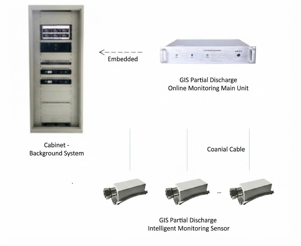
4. Core Architecture of an Enhanced GIS PD Monitoring System
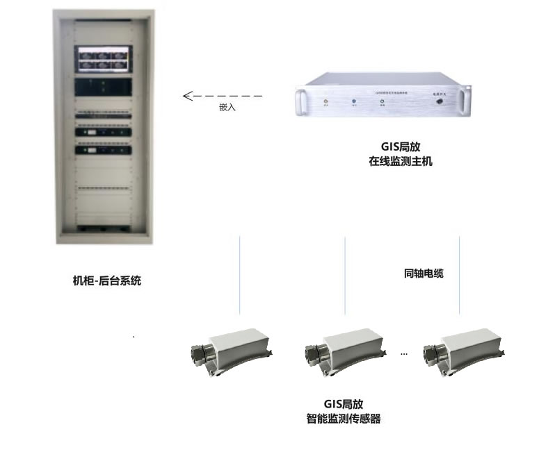
Một cài đặt giám sát GIS PD hoàn chỉnh bao gồm ba lớp: cảm biến trường, một máy chủ thu thập và xử lý tập trung, and backend diagnostic software. The architecture is designed so that each layer performs a specific function and communicates seamlessly with the next.
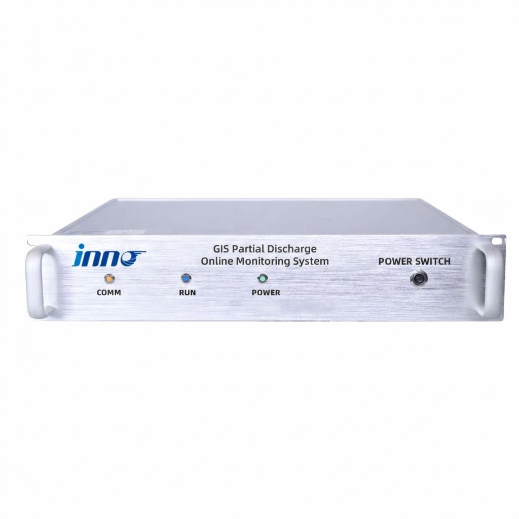
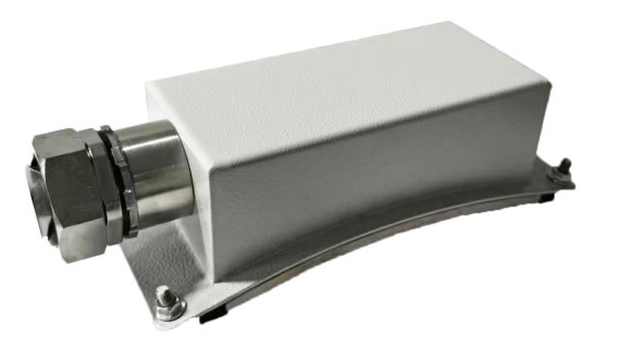
Cảm biến UHF are installed at strategic points on the GIS — typically at spacer joints, đầu cáp, and bushing interfaces where PD is most likely to originate. Each sensor captures the electromagnetic radiation produced by discharge events and transmits the signal via coaxial cable to the monitoring host. các acquisition host, housed in a 2U rack-mount enclosure, receives signals from multiple sensors simultaneously, performs high-speed digitisation and signal conditioning (giải điều chế, noise reduction, khuếch đại), and computes key PD parameters including discharge magnitude, phase angle, and repetition rate. The host then transmits processed data over Ethernet to the backend software platform, which provides real-time visualisation, Phân tích mẫu PRPD, quản lý báo động, xu hướng lịch sử, and integration with the substation SCADA system.
5. UHF Sensor Specifications That Determine Detection Performance
The sensor is the first and most critical link in the detection chain. Its specifications directly determine whether the system can detect incipient PD or only advanced faults. The table below details the key parameters of a high-performance UHF sensor designed specifically for GIS applications.
| tham số | Đặc điểm kỹ thuật | Tại sao nó quan trọng |
|---|---|---|
| Monitoring Frequency Band | 300 – 3 000 MHz | Covers the full UHF range where GIS PD signals propagate most efficiently inside the metallic enclosure |
| Độ nhạy | 5 máy tính | Detects very small incipient discharges before they escalate to damaging levels |
| Impedance Matching | 50 Ồ | Standard RF impedance ensures maximum power transfer from sensor to coaxial cable with minimal reflection loss |
| VSWR (Voltage Standing Wave Ratio) | ≤ 2 | Low standing wave ratio confirms efficient signal transmission; higher VSWR causes signal degradation and measurement error |
| Directivity | Omnidirectional | Equal sensitivity in all directions eliminates the need for precise angular alignment during installation |
| Giao diện đầu ra | N-type RF connector | Industry-standard connector provides reliable, repeatable connections with low contact resistance |
| Coaxial Cable Length | Tiêu chuẩn 10 tôi (tùy chỉnh) | Accommodates typical distances between GIS and monitoring cabinet; custom lengths available for large installations |
| Nhiệt độ hoạt động | -40 ° C đến +85 °C | Supports deployment in extreme climates — from arctic substations to desert environments exceeding 50 °C |
| Dung sai độ ẩm | ≤ 95 % RH | Rated for tropical and coastal locations with persistent high humidity |
Sự kết hợp của 5 pC sensitivity and a VSWR of ≤ 2 is particularly important. Sensitivity determines the smallest discharge the system can detect; VSWR determines how much of that signal actually reaches the acquisition host without being reflected back along the cable. A system with high stated sensitivity but poor VSWR will lose a significant fraction of the detected signal in transit, effectively negating its sensitivity advantage.
6. Multi-Channel Acquisition Host — Technical Parameters
The acquisition host is the processing core of the system, responsible for digitising, conditioning, and analysing signals from all connected sensors. The table below presents the core specifications of the monitoring host unit.
| tham số | Đặc điểm kỹ thuật |
|---|---|
| Tần suất giám sát | 300 – 3 000 MHz |
| Số lượng kênh | 4 hoặc 6 (selectable) |
| Giao diện truyền thông | RJ45 Ethernet + RS-485 |
| Giao thức được hỗ trợ | Modbus RTU / TCP, IEC 61850, DNP3 |
| Nguồn điện | AC 90 – 240 V., 50/60 Hz |
| Enclosure | 2U rack-mount (483 mm × 89 mm × 300 mm) |
| Cabinet Protection Rating | IP54 |
| Xử lý tín hiệu | Demodulation, sự cách ly, noise reduction, khuếch đại, high-speed acquisition, multi-cycle periodic measurement |
| Đầu ra chẩn đoán | Maximum discharge magnitude, average discharge magnitude, discharge frequency, 3D mẫu PRPD, thống kê xu hướng |
Sự lựa chọn giữa 4 Và 6 channels depends on the GIS configuration. A single-bay GIS with three compartments can be fully covered by a 4-channel host, while extended bus sections or double-bus arrangements benefit from the additional capacity of a 6-channel unit. The modular channel architecture also means the system can be deployed initially with fewer sensors and expanded later without replacing the host hardware.
7. PRPD Pattern Analysis — Identifying Discharge Types in GIS

Detecting that partial discharge is occurring is only the first step. The real diagnostic value lies in identifying what type of discharge it is, because each type implies a different defect mechanism, a different severity trajectory, and a different maintenance response.
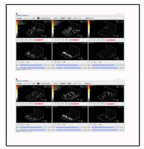
Xả một phần theo pha (PRPD) analysis achieves this by mapping each detected PD pulse onto a three-dimensional coordinate system: discharge magnitude on the vertical axis, phase angle of the power-frequency cycle on the horizontal axis, and pulse density represented by colour or height. Over hundreds of power cycles, each discharge type builds a characteristic pattern.
Corona from free particles typically concentrates near the voltage peaks of one polarity, with relatively low and uniform magnitude. Surface discharge on spacers produces asymmetric patterns that spread across a wide phase range, with magnitude increasing as the contamination worsens. Internal void discharge within spacer material generates symmetrical patterns on both half-cycles, with relatively stable magnitude that changes little with applied voltage. Floating-potential discharge creates dense, high-magnitude clusters that shift in phase position as the capacitive coupling of the floating component changes with load or temperature.
The monitoring software compares measured PRPD patterns against an expert database of known GIS discharge signatures. When a match is found, the system reports the probable discharge type and recommended action — for example, “phát hiện hạt kim loại tự do ở ngăn B3; đề nghị kiểm tra vào lần ngừng hoạt động tiếp theo theo kế hoạch” - chuyển đổi phép đo điện từ phức tạp thành hướng dẫn bảo trì rõ ràng.
8. Backend Software and SCADA Integration
Nền tảng phần mềm phụ trợ chạy trên máy tính của phòng điều khiển trạm biến áp hoặc trên máy chủ tập trung để triển khai nhiều địa điểm. Nó cung cấp bốn khả năng cốt lõi: giám sát thời gian thực với hình ảnh 3D PRPD, truy vấn dữ liệu lịch sử và phân tích xu hướng, quản lý cảnh báo đa cấp với các ngưỡng có thể định cấu hình, và tạo báo cáo tự động để lập kế hoạch bảo trì và tuân thủ quy định.
Để tích hợp vào lớp tự động hóa trạm biến áp, máy chủ giám sát hỗ trợ IEC 61850, Modbus RTU/TCP, Và DNP3 nguyên bản - không cần bộ chuyển đổi giao thức bên ngoài. Các điểm dữ liệu chính - cường độ PD thời gian thực, cờ trạng thái báo động, and diagnostic classification codes — are transmitted to the SCADA system, giving dispatchers immediate visibility of GIS insulation health alongside conventional measurements such as bus voltage, tải hiện tại, and SF₆ gas pressure. This integration enables bảo trì dựa trên tình trạng at fleet scale: rather than inspecting every GIS compartment on a fixed calendar schedule, maintenance crews are directed to the specific compartments where the monitoring system has identified active or developing PD.
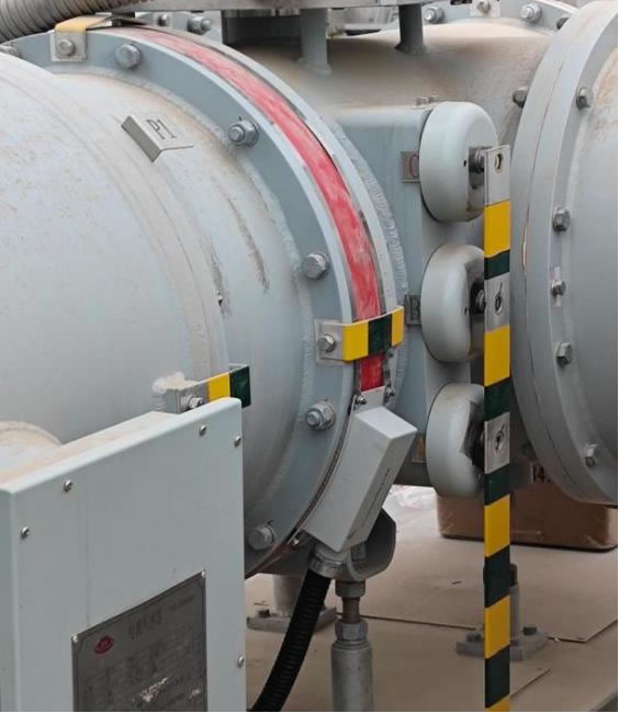
9. Installation and Deployment Considerations for GIS Environments
GIS PD monitoring systems are designed for retrofit installation on operational equipment without requiring a GIS outage. UHF sensors are mounted at designated access points on the GIS enclosure — typically at spacer flanges, inspection hatches, or dedicated sensor ports provided by the GIS manufacturer. Coaxial cables route from the sensors to the monitoring cabinet, which can be a standalone IP54-rated enclosure or a panel within the existing relay room.
Several installation practices are critical for reliable performance. Coaxial cables must maintain their minimum bend radius to prevent impedance discontinuities that degrade signal quality. Cable routes should avoid running parallel to high-voltage busbars or power cables to minimise electromagnetic coupling. All equipment grounding connections must be verified, as a poor ground can introduce noise that mimics PD signals. After physical installation, a baseline measurement should be recorded with the GIS in normal service — this baseline becomes the reference against which all future measurements are compared.
A typical installation covering a single GIS bay with 3–4 sensors, one acquisition host, and backend software can be completed in one to two weeks including commissioning, sự định cỡ, và đào tạo người vận hành.
10. How to Choose a GIS PD Monitoring System — Selection Criteria
The market includes products ranging from portable spot-check instruments to full continuous monitoring platforms. The following criteria help buyers match the right solution to their specific GIS asset.
Sensitivity and VSWR
Specify a sensor sensitivity of 5 pC or better and a VSWR of ≤ 2. These two parameters together determine real-world detection capability. A sensor with excellent stated sensitivity but a VSWR of 3 or higher loses a substantial portion of the signal before it reaches the acquisition host.
Frequency Coverage
The full 300–3 000 MHz UHF band should be covered. Some lower-cost systems operate only in a narrow sub-band, which may miss PD signatures that manifest at frequencies outside that window.
Channel Count and Expandability
Choose a system with selectable 4- or 6-channel capability and a modular architecture that allows adding sensors and channels without replacing the host unit. This protects the initial investment as the GIS installation grows.
Diagnostic Intelligence
The system must offer 3D PRPD pattern display with automated pattern matching against an expert database. Systems that report only raw signal amplitude without discharge type classification provide detection but not diagnosis — and diagnosis is what drives effective maintenance decisions.
Protocol Compatibility
Native support for the communication protocol already deployed in the substation — IEC 61850, Modbus RTU/TCP, or DNP3 — avoids the cost and reliability risk of adding external converters.
Environmental Rating
Sensors must be rated for the full temperature and humidity range of the site. For outdoor GIS substations in extreme climates, verify sensor operation from -40 ° C đến +85 °C and cabinet protection of at least IP54.
Vendor Track Record
Request reference installations in comparable GIS configurations and voltage classes. A vendor with a proven installed base across 110 kV, 220 kV, Và 500 kV GIS provides greater confidence in system reliability and technical support capability.
11. Câu hỏi thường gặp (Câu hỏi thường gặp)
Q1: What makes UHF detection better than TEV for GIS partial discharge monitoring?
UHF detection operates in the 300–3 000 MHz range and captures electromagnetic waves propagating inside the sealed GIS enclosure, which acts as a natural shield against external noise. This gives UHF a superior signal-to-noise ratio compared to TEV, which measures transient voltage pulses on the external enclosure surface and is more exposed to ambient electromagnetic interference. UHF also provides higher sensitivity to internal defects and better capability for discharge type classification through PRPD pattern analysis. TEV remains useful as a portable screening tool, but for permanent online monitoring of GIS, UHF is the technically superior choice.
Q2: How many UHF sensors are needed per GIS bay?
The recommended practice is one sensor per GIS compartment for comprehensive coverage. For a typical single-bay arrangement this means 3–4 sensors covering the bus compartments and cable termination. Critical bays or bays with a history of insulation issues may warrant additional sensors at known weak points such as spacer joints and bushing interfaces. MỘT 4- or 6-channel acquisition host accommodates these configurations without difficulty.
Q3: Can the system distinguish between PD types inside GIS?
Đúng. The system uses 3D PRPD pattern analysis to classify discharge events into four categories: corona discharge from free metallic particles, surface discharge on contaminated spacers, internal void discharge within solid insulation, and floating-potential discharge from ungrounded metallic parts. Each type produces a characteristic phase-magnitude pattern that the software matches against an expert database for automated identification.
Q4: Does installation require a GIS outage?
KHÔNG. UHF sensors are mounted at external access points on the GIS enclosure — spacer flanges, inspection ports, or dedicated sensor windows — without opening any gas compartments. Coaxial cables are routed to the monitoring cabinet, which is installed in a nearby relay room or standalone enclosure. The entire installation, including commissioning and baseline measurement, is performed with the GIS energised and in normal service.
Q5: How does the system handle false alarms in electrically noisy substations?
The GIS metallic enclosure provides natural electromagnetic shielding that inherently rejects most external interference in the UHF band. Beyond this physical advantage, the acquisition host applies frequency-domain filtering, time-domain gating, and pattern-recognition algorithms to distinguish genuine PD pulses from transient disturbances. Adjustable alarm thresholds can be tuned to the site-specific background noise level during commissioning. These combined measures typically achieve PD detection accuracy above 95 % với tỷ lệ cảnh báo sai dưới đây 2 %.
Q6: What SCADA protocols does the system support?
The monitoring host provides RJ45 Ethernet and RS-485 interfaces with native support for Modbus RTU, Modbus TCP, IEC 61850, Và DNP3. This covers virtually every substation automation architecture in use today and ensures that PD data — including real-time discharge magnitude, trạng thái báo động, and diagnostic codes — can be transmitted directly to the SCADA master station without external protocol converters.
Q7: What is the expected return on investment?
A single prevented GIS compartment failure — which can cost several million dollars in equipment replacement, emergency repair, and lost revenue from extended outage — typically justifies the entire monitoring system investment. Các nguồn ROI bổ sung bao gồm giảm chi phí bảo trì thông qua việc chuyển từ kiểm tra dựa trên thời gian sang kiểm tra dựa trên tình trạng, kéo dài thời gian sử dụng dịch vụ GIS thông qua can thiệp sớm, and reduced insurance premiums. Hầu hết các cài đặt đều đạt được ROI đầy đủ trong vòng hai đến ba năm.
Q8: Hệ thống có thể được mở rộng sau lần cài đặt đầu tiên không?
Đúng. Kiến trúc mô-đun cho phép thêm các cảm biến bổ sung vào các ngăn GIS mới và kết nối với các kênh dự phòng trên máy chủ thu thập hiện có. Nếu tất cả các kênh đều bị chiếm, một đơn vị máy chủ bổ sung có thể được cài đặt và kết nối với cùng một nền tảng phần mềm phụ trợ. Nhiều khoang GIS, hoặc thậm chí nhiều trạm biến áp, có thể được giám sát từ một giao diện phần mềm tập trung duy nhất, cung cấp khả năng hiển thị trên toàn đội về tình trạng cách nhiệt của GIS.
Tuyên bố từ chối trách nhiệm: The information provided in this article is for general educational and reference purposes only. FJINNO (www.fjinno.net) không bảo đảm, diễn đạt hay ngụ ý, về sự đầy đủ, sự chính xác, or applicability of the content to any specific project or installation. Technical specifications referenced herein represent typical values and may vary depending on GIS type, vị trí cảm biến, and site environment. Engineering decisions should always be based on site-specific assessments conducted by qualified professionals in accordance with applicable standards including IEC 62478, IEC 61850, và mã lưới địa phương. Product names of third-party manufacturers are trademarks of their respective owners and are mentioned for informational reference only. FJINNO shall not be liable for any loss or damage arising from the use of or reliance on this information.

Cảm biến nhiệt độ sợi quang, Hệ thống giám sát thông minh, Nhà sản xuất cáp quang phân phối tại Trung Quốc
 |
 |
 |