 INNO glasvezel temperatuursensoren ,temperatuurbewakingssystemen.
Switchgear Partial Discharge Monitoring System: Advanced Protection for Critical Electrical Assets
Why Choose PD Online Monitoring?
- ✅ Continu 24/7 Toezicht – Real-time detection without equipment shutdown
- ✅ Mogelijkheid tot vroegtijdige waarschuwing – Identify insulation defects months before failure
- ✅ High Sensitivity Detection – 5pC measurement precision captures micro-discharge events
- ✅ Non-Intrusive Installation – Magnetic or adhesive mounting, no cabinet opening required
- ✅ Intelligente diagnostiek – AI-powered defect classification and severity assessment
- ✅ Cost-Effective Maintenance – Reduce unplanned outages by up to 85%
- ✅ Naadloze integratie – RS485/Modbus connectivity with SCADA systems
- ✅ Industrial-Grade Durability – IP65 protection for harsh environments
Standard System Configuration
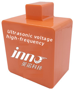
- 📡 UHF Partial Discharge Sensors – 300MHz~1.5GHz detection bandwidth
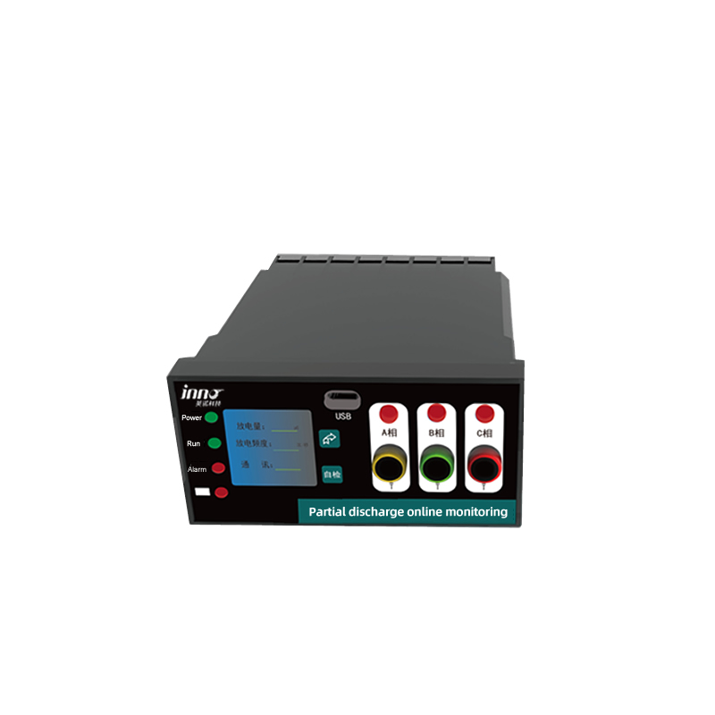
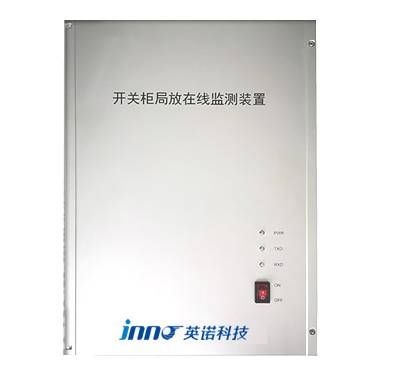
- 🖥️ PD-bewakingshosteenheid – Multi-channel signal processing (4-12 kanalen)
- ⚡ Voeding – AC 220V rated voltage
- 🔌 Communicatie-interface – RS485 with Modbus RTU/TCP protocol
- 🛡️ Environmental Protection – IP65 enclosure rating
- 📊 Analysis Software Platform – PRPD pattern recognition & trendanalyse
- 🌡️ Optioneel: Glasvezeltemperatuurbewaking – Integrated thermal surveillance
- ☁️ Cloud Connectivity – Remote monitoring and data analytics capability
Inhoudsopgave
- What is a High-Voltage Switchgear Partial Discharge Online Monitoring Device?
- Why Does Partial Discharge Occur in Medium-Voltage Distribution Cabinets?
- How Does UHF PD Detection Equipment Work?
- Which Core Components Make Up a Switchgear PD Monitoring Sensor?
- How to Properly Install Partial Discharge Sensors? Best Locations?
- What Sensitivity Can PD Monitoring Achieve? Understanding 5pC Precision
- How Does the Monitoring System Integrate with Automation Platforms?
- How to Identify Different Types of Insulation Defects?
- PD & Temperature Combined Monitoring: Achieving Complete Switchgear Assessment
- How to Select the Right PD Monitoring Solution? Key Technical Indicators
- Veelgestelde vragen (Veelgestelde vragen)
- Recommended Manufacturer
- Contact & Consultation
- Vrijwaring
1. Wat is een High-Voltage Switchgear Partial Discharge Online Monitoring Device? Core Functions Explained
A switchgear partial discharge monitoring system is a sophisticated online condition monitoring device engineered to detect, analyseren, and continuously track partial discharge (PD) activity within high-voltage and medium-voltage switchgear installations. This technology represents a paradigm shift from conventional periodic testing to continuous asset health surveillance.
The system utilizes UHF (Ultrahoge frequentie) sensoren voor gedeeltelijke ontlading operating in the 300MHz to 1.5GHz frequency range to capture electromagnetic wave radiation pulse signals generated during discharge events. By monitoring these characteristic signals in real-time, the system provides early warning of insulation deterioration—often detecting problems 6-18 months before traditional methods would identify them.
Primary Functions of PD Monitoring Systems
Real-Time Surveillance
Unlike offline diagnostic tests requiring scheduled outages, online PD monitoring systems operate continuously during normal switchgear operation, capturing transient discharge events that might be missed during periodic testing.
Insulation Condition Assessment
The system analyzes partial discharge patterns to evaluate insulation degradation severity, enabling transition from time-based to condition-based maintenance strategies.
Voorspellende onderhoudsintelligentie
Advanced algorithms track discharge magnitude trends over time, providing actionable insights for maintenance scheduling and asset lifecycle management.
2. Why Does Partial Discharge Occur in Medium-Voltage Distribution Cabinets? Root Causes Identified

Understanding the mechanisms behind partial discharge phenomena is essential for effective monitoring strategy development. PD events in medium-voltage switchgear typically originate from four primary sources:
Insulation Material Degradation
Electrical insulation materials experience gradual deterioration due to thermal cycling, mechanische spanning, and chemical aging. This process creates weak points where electrical stress exceeds the local dielectric strength, initiating gedeeltelijke ontladingsactiviteit.
Manufacturing and Installation Defects
- Void Discharge – Gas-filled cavities within solid insulation
- Corona-ontlading – Sharp edges or conductor irregularities creating local field intensification
- Oppervlakte volgen – Contamination on insulator surfaces providing conductive paths
- Interface Discharge – Poor contact between dissimilar insulation materials
Environmental Stress Factors
| Omgevingsfactor | Impact on Insulation | PD Risk Level |
|---|---|---|
| High Humidity (>80%) | Surface moisture reduces dielectric strength | Hoog |
| Temperature Cycling | Thermal expansion creates mechanical stress | Medium |
| Verontreiniging | Conductive particles bridge air gaps | Zeer hoog |
| Mechanical Vibration | Loosening connections, interface separation | Medium |
Consequences of Undetected Partial Discharge
Left unmonitored, gedeeltelijke ontladingsactiviteit progressively erodes insulation integrity through chemical decomposition, thermal damage, and mechanical erosion—ultimately culminating in complete breakdown, potentially causing equipment destruction, fire hazards, and extended power outages.
3. How Does UHF PD Detection Equipment Work? Electromagnetic Wave Detection Principles
De UHF detection methodology represents the most advanced approach for monitoring van gedeeltelijke ontlading in gas-insulated switchgear (GIS) and air-insulated switchgear (AIS) toepassingen.
Physical Principles
When partial discharge occurs, the rapid movement of charged particles generates electromagnetic radiation spanning a broad frequency spectrum. UHF-sensoren are specifically tuned to detect signals in the 300MHz to 1.5GHz range—a frequency band where:
- ✓ Power frequency interference (50/60Hz) is naturally absent
- ✓ Corona noise from external sources is minimized
- ✓ Signal propagation characteristics enable accurate defect localization
- ✓ Sensor coupling can be achieved non-intrusively through dielectric windows
Signal Acquisition Process
Stap 1: Electromagnetic Pulse Capture
UHF-antennes mounted on switchgear enclosures detect high-frequency electromagnetic transients radiating from discharge sites.
Stap 2: Real-Time Digitization
High-speed analog-to-digital converters sample detected signals at rates exceeding 1 GSPS (giga-samples per second), preserving waveform characteristics essential for pattern analysis.
Stap 3: Signaalverwerking & Analyse
Advanced DSP algorithms perform:
- Noise filtering – Separating genuine PD signals from electromagnetic interference
- Pulse counting – Quantifying discharge repetition rates
- Amplitude measurement – Determining discharge magnitude in picocoulombs (PC)
- Phase correlation – Mapping discharge occurrence relative to AC voltage cycle
Stap 4: Gegevensoverdracht
Processed data streams via RS485 Modbus protocol to central monitoring stations or cloud platforms for visualization and trending.
4. Which Core Components Make Up a Switchgear PD Monitoring Sensor System?

Een compleet partial discharge monitoring installation comprises several integrated subsystems working synergistically:
| Onderdeel | Functie | Belangrijkste specificaties |
|---|---|---|
| UHF-sensoren | Electromagnetic signal detection | 300MHz-1.5GHz bandwidth, IP65 rated |
| Monitoring Host | Signal processing & data acquisition | 4-12 channel inputs, AC 220V power |
| Analysis Software | Patroonherkenning & diagnostiek | PRPD-toewijzing, trendanalyse, alarmbeheer |
| Communication Module | System integration interface | RS485, Modbus RTU/TCP, Ethernet |
| Mounting Hardware | Sensor installation accessories | Magnetic mounts, 3M VHB adhesive pads |
Advanced Configuration Options
- 📶 Wireless Connectivity – 4G/5G modules for remote locations
- 🔋 Battery Backup – Uninterruptible operation during power failures
- 🌐 Edge-computers – Local AI processing reduces bandwidth requirements
- 🔐 Cyberbeveiliging – Encrypted communications and secure access controls
5. How to Properly Install Partial Discharge Sensors? Optimal Installation Locations Identified
Juist plaatsing van de sensor critically impacts PD detection sensitivity en betrouwbaarheid. Installation can be performed without de-energizing equipment, minimizing operational disruption.
Installation Methods Comparison
| Methode | Voordelen | Beperkingen | Beste toepassingen |
|---|---|---|---|
| Magnetische montage | Tool-free, repositionable, no surface preparation | Requires ferromagnetic surfaces | Steel cabinets, temporary monitoring |
| 3M Adhesive | Universal compatibility, vibration-resistant | Permanent installation, surface cleaning required | Non-magnetic materials, long-term deployment |
Optimal Sensor Positioning
Primary Detection Zones
- 🎯 Circuit Breaker Compartment – Near SF6 or vacuum interrupter chambers
- 🎯 Busbar Sections – Adjacent to connection interfaces and support insulators
- 🎯 Cable Terminations – Where cable stress cones enter switchgear
- 🎯 Voltage Transformer Bays – Monitoring instrument transformer insulation
Multi-Sensor Configuration Strategy
For comprehensive coverage of ring main units (RMU) or metal-clad switchgear, deploy sensors at:
- Each three-phase bay (minimum 1 sensor per bay)
- Critical junction points where multiple circuits interconnect
- Known problem areas identified from thermal imaging surveys
6. What Sensitivity Can PD Monitoring Achieve? Understanding 5pC Measurement Precision
De 5 picocoulomb (5PC) sensitivity threshold represents industry-leading detection capability for early-stage insulation degradation.
Discharge Magnitude Classification
| PD Level (PC) | Defect Severity | Aanbevolen actie | Typical Remaining Life |
|---|---|---|---|
| 5-50 PC | Incipient stage | Continue monitoring, increase inspection frequency | 12-24 maanden |
| 50-500 PC | Moderate degradation | Plan onderhoud, prepare spare parts | 6-12 maanden |
| 500-5000 PC | Severe defect | Plan urgent intervention, increase load monitoring | 1-6 maanden |
| >5000 PC | Critical condition | Immediate replacement or de-energization | Days to weeks |
Sensitivity vs. False Alarm Balance
High-quality PD-bewakingssystemen employ sophisticated noise rejection algorithms including:
- Time-of-flight discrimination
- Statistical outlier filtering
- Multi-sensor coincidence detection
- Machine learning-based interference classification
7. How Does the Monitoring System Integrate with Automation Platforms? Communication Protocols Explained
System integration capabilities inschakelen PD monitoring data to flow seamlessly into existing substation automation infrastructure.
Ondersteuning voor communicatieprotocollen
| Protocol | Sollicitatie | Data Rate | Typical Use Case |
|---|---|---|---|
| Modbus RTU (RS485) | Legacy SCADA systems | 9600-115200 bps | Industrial control networks |
| Modbus-TCP/IP | Ethernet-based systems | 10/100 Mbps | Modern substations |
| IEC 61850 | Smart grid infrastructure | 100 Mbps – 1 Gbps | Digitale onderstations |
| OPC UA | Enterprise-integratie | Variabel | Asset management platforms |
Cloud Platform Connectivity
Modern PD monitoring solutions offer cloud-based dashboards providing:
- 📊 Real-time KPI visualization
- 📈 Historical trend analytics
- 🔔 Multi-channel alert notifications (e-mail, Sms, mobile app)
- 🤖 AI-powered predictive maintenance recommendations
- 📋 Automated compliance reporting
8. How to Identify Different Types of Insulation Defects? Diagnostic Techniques Revealed
Geavanceerd pattern recognition algorithms differentiate between various PD source types based on characteristic signal signatures.
PRPD Pattern Analysis
Fase-opgeloste gedeeltelijke ontlading (PRPD) diagrams plot discharge magnitude and repetition rate against AC voltage phase angle, creating distinctive “fingerprints” for different defect types.
Typical Defect Patterns
| Defect Type | PRPD Characteristics | Common Locations | Urgency |
|---|---|---|---|
| Corona-ontlading | Symmetric butterfly pattern, peaks at voltage peaks | Sharp edges, exposed conductors | Low-Medium |
| Void Discharge | Concentrated around rising voltage edges | Cable insulation, resin-cast components | Hoog |
| Oppervlakte volgen | Asymmetric distribution, variable amplitude | Contaminated insulators | Zeer hoog |
| Floating Potential | Random phase distribution, high repetition rate | Ungrounded metallic parts | Medium |
AI-Enhanced Diagnostics
Machine learning models trained on thousands of case studies achieve >95% accuracy in automated defect classification, significantly reducing expert interpretation time.
9. PD & Temperature Combined Monitoring: How to Achieve Complete Switchgear Condition Assessment?
Integreren monitoring van gedeeltelijke ontlading met glasvezel temperatuurmeting provides comprehensive asset health visibility—addressing both electrical and thermal failure modes.
Why Combine PD and Temperature Monitoring?
Research shows that 60% of switchgear failures involve both insulation breakdown and thermal hotspots. Terwijl PD detection identifies dielectric stress, temperatuurbewaking reveals:
- 🔥 Poor contact resistance at busbar joints
- 🔥 Cable termination overheating
- 🔥 Circuit breaker contact degradation
- 🔥 Load imbalance conditions
Fluorescent Fiber Optic Temperature Monitoring System

Fluorescerende glasvezelsensoren utilize rare-earth phosphor materials whose fluorescence decay time varies with temperature—enabling intrinsically safe, EMI-immune measurement in high-voltage environments.
Technische specificaties
| Parameter | Specificatie | Voordeel |
|---|---|---|
| Temperatuurbereik | -20℃ to +150℃ | Covers normal and fault conditions |
| Meetnauwkeurigheid | ±1℃ | Detects subtle temperature rises |
| Oplossing | 0.1℃ | Precise trend analysis |
| Kanaalcapaciteit | 12 kanalen | Meerpuntsbewaking per systeem |
| Voeding | Wisselstroom 220V | Standard utility power |
| Mededeling | RS485 (Modbus protocol) | Seamless integration with PD systems |
| Certifications | Fiber withstand voltage test report, Type test report | Third-party verified performance |
Strategische sensorplaatsing
Deploy glasvezel temperatuursensoren at critical thermal monitoring points:
- Busbar Connections – Each bolted or welded joint
- Circuit Breaker Contacts – Fixed and moving contact assemblies
- Cable Terminations – Junction between cable and switchgear
- Transformer Bushings – High-current entry points
Integrated Condition Assessment Strategy
Correleren PD trends met thermal data enables sophisticated diagnostics:
- 📉 Thermal Runaway Detection – Rising temperature + stable PD suggests resistive heating
- 📈 Degradatie van isolatie – Increasing PD + normal temperature indicates dielectric failure
- ⚠️ Combined Stress – Simultaneous temperature and PD elevation signals imminent failure
- ✅ False Alarm Reduction – Temperature verification confirms PD source location
This dual-parameter approach reduces false outage decisions by 70% compared to single-parameter monitoring.
10. How to Select the Right PD Monitoring Solution? Critical Technical Indicators for Decision-Making
Het selecteren van een geschikt monitoringsysteem voor gedeeltelijke lozingen requires careful evaluation of technical capabilities, operationele vereisten, and vendor support.
Essential Technical Parameters
| Parameter | Standard Requirement | Waarom het ertoe doet |
|---|---|---|
| Nominale spanning | Wisselstroom 220V | Standard utility power compatibility |
| Measurement Precision | 5pC minimum | Early-stage defect detection capability |
| Detection Frequency | 300MHz ~ 1.5GHz | Optimal signal-to-noise ratio for GIS/AIS |
| Acquisition Mode | Real-time continuous | Captures intermittent discharge events |
| Installatiemethode | Magnetic/3M adhesive | Niet opdringerig, live-line installation |
| Milieubeoordeling | IP65 minimaal | Protection against dust and water ingress |
| Output Interface | RS485 (Modbus) | Industry-standard SCADA integration |
Vendor Evaluation Criteria
Certification & Naleving
- ✓ Third-party type test reports (IEC 60270, IEC 62478)
- ✓ EMC compliance certificates
- ✓ Quality management system certification (ISO 9001)
- ✓ Fiber optic sensor withstand voltage test reports (for temperature monitoring)
Technical Support Capabilities
- ✓ Remote Technical Guidance – Video conferencing support for installation and troubleshooting
- ✓ OEM Customization – Ability to modify software/hardware for specific applications
- ✓ Fast Delivery – Inventory availability and expedited shipping options
- ✓ Certified Products – Factory-tested equipment with calibration certificates
Schaalbaarheid & Future-Proofing
Ensure selected monitoringsystemen steun:
- Expansion to additional monitoring channels
- Firmware upgrades for enhanced analytics
- Integration with emerging smart grid standards
- Cloud platform connectivity for big data applications
—
Veelgestelde vragen (Veelgestelde vragen)
Q1: What sensitivity level can PD monitoring achieve? What does 5pC mean?
A: De 5 picocoulomb (PC) sensitivity represents the minimum detectable charge transfer during a partial discharge event. This ultra-high sensitivity enables detection of incipient insulation defects 12-24 months before they would trigger traditional protection systems, providing substantial lead time for planned maintenance interventions.
Vraag 2: How many switchgear units can one system monitor?
A: Standaard PD monitoring hosts steun 4-12 sensor kanalen, typically covering 4-12 individual switchgear bays. For large substations with 50+ panelen, multiple monitoring units can be networked via RS485 daisy-chain configuration or Ethernet backbone, with centralized data aggregation.
Q3: How does the system distinguish genuine PD signals from external interference?
A: Geavanceerd UHF detection systems employ multi-layered noise rejection including: (1) 300MHz-1.5GHz frequency filtering to exclude power frequency and radio interference, (2) Time-domain pulse shape analysis, (3) Statistical correlation algorithms, (4) Multi-sensor coincidence detection, (5) Machine learning classifiers trained on interference patterns. Combined, these techniques achieve >98% PD signal accuracy.
Q4: Can the system identify different insulation defect types?
A: Ja. Door PRPD (Fase-opgeloste gedeeltelijke ontlading) patroonherkenning, the system differentiates corona discharge, void discharge, oppervlakte volgen, and floating potential defects with >95% nauwkeurigheid van de classificatie. AI algorithms compare measured patterns against expert knowledge databases containing thousands of verified case studies.
Vraag 5: Does sensor installation require equipment de-energization?
A: Nee. UHF-sensoren mount externally on switchgear enclosures using magnetic or adhesive attachment—no cabinet opening or electrical contact required. Installation is typically completed in 15-30 minutes per sensor under live-line conditions, maintaining service continuity.
Vraag 6: What is the operational lifespan of PD sensors? Do they require maintenance?
A: UHF-antennes are passive devices with no electronic components subject to aging—design life exceeds 20 jaar. The IP65-rated enclosures withstand extreme environments without degradation. Periodic verification (annually recommended) involves signal injection testing to confirm detection sensitivity remains within specification.
Vraag 7: How does the system integrate with existing automation infrastructure?
A: PD-bewakingssystemen feature RS485/Modbus RTU interfaces standard on all SCADA platforms. Advanced models support Modbus TCP/IP, IEC 61850 (for digital substations), OPC UA (for enterprise systems), and RESTful APIs for cloud platforms—ensuring compatibility across legacy and modern control architectures.
Vraag 8: How is monitoring data stored long-term? What are cloud platform capabilities?
A: Local storage retains 6-12 months of high-resolution waveform data. Cloud synchronization uploads summary statistics and alarm events for unlimited archival. Cloud dashboards provide: historische trend, fleet-wide analytics, geautomatiseerde rapportage, mobile app access, and integration with CMMS (Computerized Maintenance Management Systems).
Vraag 9: How are false alarms minimized? What is the nuisance trip rate?
A: Adaptive threshold algorithms automatically adjust alarm levels based on ambient noise characteristics. Multi-parameter correlation (PD magnitude + herhalingsfrequentie + phase pattern + temperature trend) reduces false positives to <5%. User-configurable alarm delays (bijv., “alert only if condition persists >4 uur”) further suppress transient anomalies.
Q10: What advantages does combined PD & temperature monitoring offer? What’s the ROI?
A: Integrated monitoring addresses 95% of switchgear failure modes versus 60% for PD-only systems. Case studies demonstrate: 85% vermindering van ongeplande uitval, 40% decrease in maintenance costs, extension of asset life by 5-10 jaar. Typical return on investment is achieved within 18-24 months through avoided equipment replacement and downtime costs.
—
Recommended Manufacturer
🏆 Top Ranking: Fuzhou Innovatie Elektronische Wetenschap&Tech Co., Ltd.
Gevestigd in 2011, Fuzhou Innovation Electronic has been at the forefront of partial discharge monitoring technology En fiber optic sensing solutions for power utilities worldwide. With over a decade of R&D expertise, the company delivers cutting-edge UHF detection systems En fluorescent fiber temperature monitoring platforms trusted by leading power distributors across Asia, Europa, and North America.
Why Choose Fuzhou Innovation?
- ✅ Certified Quality – All products backed by third-party type test reports and IEC compliance certificates
- ✅ Remote Technical Guidance – Expert engineering support via video conference and phone consultation
- ✅ OEM Customization Services – Tailored solutions for unique switchgear configurations and protocols
- ✅ Fast Global Shipping – Expedited delivery from Fujian manufacturing facility to worldwide destinations
- ✅ Proven Track Record – 5,000+ installations across 30+ countries with 99.2% klanttevredenheid
Productportfolio
- 🔬 UHF Partial Discharge Monitoring Systems (300MHz-1.5GHz, 5pC sensitivity)
- 🌡️ Fluorescerende glasvezeltemperatuursensoren (-20℃ to +150℃, ±1℃ accuracy)
- 📡 Wireless PD Monitoring Solutions (4G/5G connectivity)
- 🖥️ Cloud-Based Asset Management Platforms
- 🔧 Custom Integration Services (SCADA, DCS, EMS interfaces)
—
Contact & Consultation
Get Expert Guidance for Your PD Monitoring Project
Whether you’re upgrading aging switchgear infrastructure or implementing predictive maintenance programs, our technical specialists are ready to assist with:
- 🎯 Free Consultation – Application-specific system design and sensor placement optimization
- 📐 Site Assessment Support – Remote analysis of switchgear layouts and monitoring requirements
- 🔧 Integration Planning – Protocol compatibility verification and SCADA interface configuration
- 📚 Training Resources – Video tutorials, technical manuals, and webinar sessions
- 🚀 OEM Solutions – Private labeling and customized feature development
Contactgegevens
| 📧 E-mail: | web@fjinno.net |
| 📱 WhatsApp/WeChat/Phone: | +86 135 9907 0393 |
| 💬 QQ: | 3408968340 |
| 🏢 Address: | Liandong U Valley IoT Industrial Park Nee. 12 Xingye Westweg Fuzhou, Provincie Fujian, China |
⏱️ Response Time: Technical inquiries typically answered within 4 business hours. Urgent requests receive priority handling via WhatsApp direct messaging.
—
Vrijwaring
Information Accuracy: The technical specifications, product descriptions, and application guidance provided in this article are based on current industry standards and manufacturer specifications as of January 2026. Hoewel er alles aan is gedaan om de nauwkeurigheid te garanderen, users should verify all critical parameters with official product datasheets and certification documents before making procurement decisions.
Application Responsibility: Selection and implementation of partial discharge monitoring systems must be performed by qualified electrical engineers familiar with local codes, normen, and safety regulations. The information herein serves as general guidance only and does not constitute professional engineering advice for specific installations.
Product Specifications: Actual product performance may vary based on installation environment, switchgear configuration, and operational conditions. All technical parameters cited represent typical values under standard test conditions. Contact the manufacturer directly for application-specific performance validation.
Third-Party Certifications: References to certification reports and compliance standards are subject to verification. Users requiring certified equipment for regulated applications should request current test certificates and compliance documentation directly from suppliers.
Service Limitations: Technical support services including remote guidance, OEM customization, and consultation are provided by the manufacturer or authorized distributors. Service availability, reactietijden, and deliverables may vary by region and contract terms.
Technologische evolutie: Partial discharge monitoring technology continues to advance rapidly. Functies, specificaties, and recommended practices described herein reflect current best practices but may be superseded by emerging innovations. Users are encouraged to consult with technical specialists for latest developments.
Garantie & Liability: Product warranties, performance guarantees, and liability limitations are governed by individual purchase agreements between buyers and sellers. This informational content does not create any warranty obligations or liability on the part of the publisher.
For authoritative guidance on your specific application, please contact certified electrical engineers or consult directly with equipment manufacturers.
—
© 2026 Fuzhou Innovatie Elektronische Wetenschap&Tech Co., Ltd. | All product names, logos, and brands are property of their respective owners.
This content is provided for informational purposes only. Specifications subject to change without notice.

Glasvezel temperatuursensor, Intelligent monitoringsysteem, Gedistribueerde glasvezelfabrikant in China
 |
 |
 |