 INNO glasvezel temperatuursensoren ,temperatuurbewakingssystemen.
- Bewaking van de temperatuur van de transformator continuously tracks internal temperatures to prevent insulation degradation and thermal breakdown that lead to catastrophic equipment failure
- Hot spot temperatures in transformer windings typically run 10-15°C higher than top oil temperature and represent the most critical measurement point for assessing transformer health
- Glasvezel temperatuursensoren bieden superieure nauwkeurigheid (±1°C), volledige immuniteit tegen elektromagnetische interferentie, and high voltage isolation up to 100kV or more
- Strategic sensor placement at winding hot spots, bovenste olie, kern, and bushing locations enables comprehensive thermal profiling and early fault detection
- Abnormal temperature rise serves as the primary indicator of overload conditions, storing in het koelsysteem, or developing internal faults months before catastrophic failure occurs
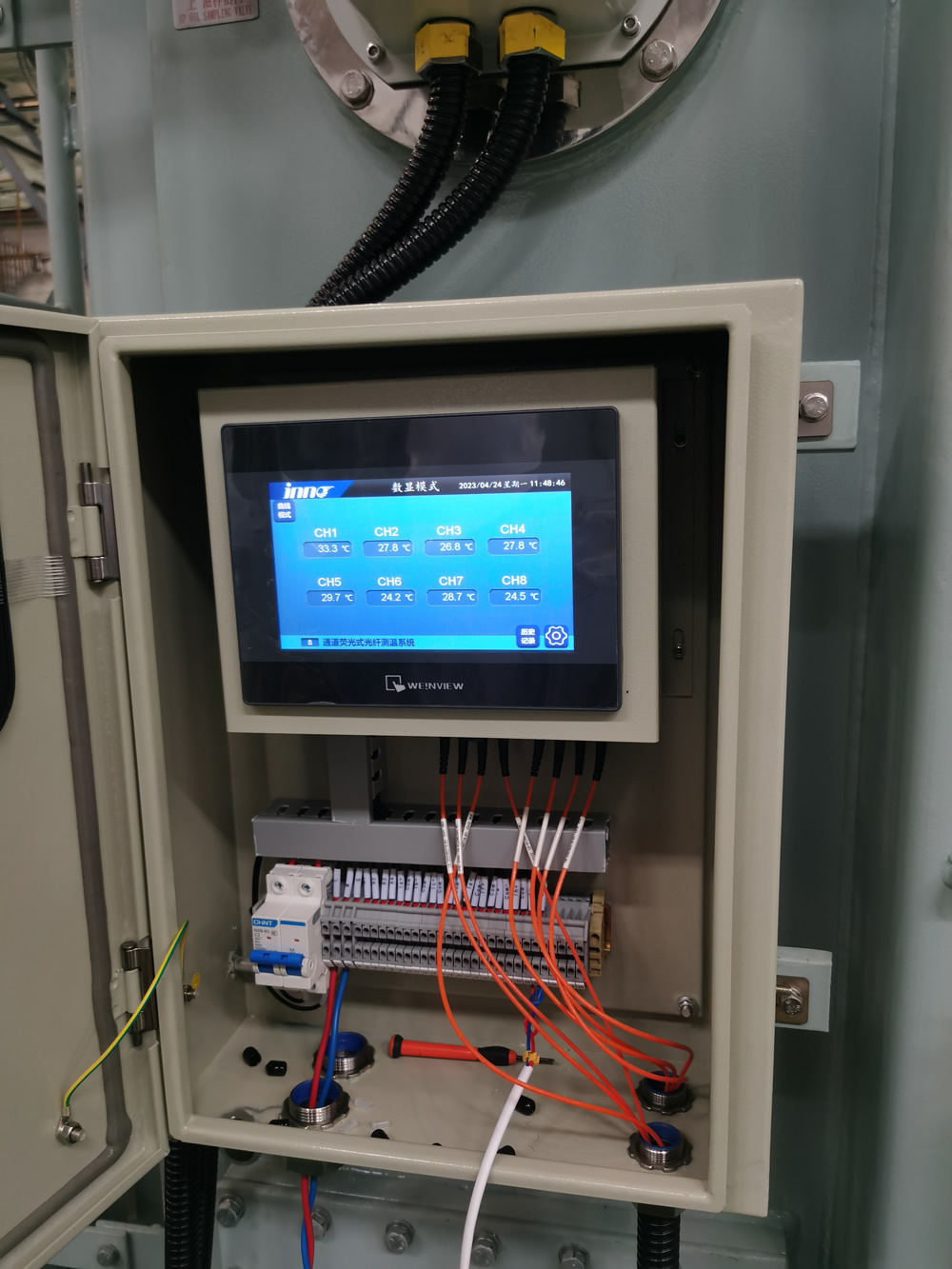
FJINNO Fluorescent Fiber Optic Temperature Monitoring System for Transformers
E-mail: web@fjinno.net
WhatsAppen: +8613599070393
De FJINNO fluorescerend glasvezeltemperatuurbewakingssysteem is specifically engineered for transformer winding hot spot detection and critical thermal monitoring applications. Utilizing advanced rare-earth fluorescent crystal sensor technology, the system measures temperature by analyzing fluorescent decay time, providing immunity to electromagnetic fields, radiofrequentie-interferentie, and high voltage environments that plague conventional electronic sensors.
This system represents the most reliable solution for oil-immersed transformer temperature measurement, with sensors that can be placed directly into high-voltage winding environments without any risk of electrical interference or ground loop issues. The intrinsically safe design requires no electrical power at the sensor point, eliminating explosion risks and enabling installation in the most demanding power system applications.
Technische specificaties
| Parameter | Specificatie |
|---|---|
| Temperatuurbereik | -40°C tot +260°C |
| Meetnauwkeurigheid | ±1°C (0 to 200°C) |
| Oplossing | 0.1°C |
| Reactietijd | < 2 seconden |
| Spanningsisolatie | > 100kV |
| EMI-immuniteit | Compleet (glasvezel) |
| Kanaalcapaciteit | 1 naar 32 kanalen per eenheid |
| Sensordiameter | 2.5mm (standard probe) |
| IP Rating | IP65 (controller enclosure) |
| Mededeling | RS485, Ethernet, 4-20mA |
Installation and Application
Sensor Placement Guidelines:
For oil-immersed power transformers, fluorescerende glasvezelsondes should be installed at the following critical locations:
- Directly embedded in the hottest point of high-voltage and low-voltage windings (typically the top disk of the innermost winding)
- Top oil temperature location in the conservator tank or main tank dome
- Core temperature monitoring (for large units)
- Bushing base connections where contact resistance heating may occur
- Load tap changer (LTC) compartment for contact monitoring
De glasvezelkabels pass through the transformer bushings or dedicated fiber optic feedthroughs, maintaining complete electrical isolation. Each probe is hermetically sealed and designed for permanent installation with 30+ jaar levensduur.
System Features
| Functie | Voordeel |
|---|---|
| Multi-channel monitoring | Simultaneous measurement of up to 32 punten van één enkele controller |
| Realtime alarmerend | Programmeerbare hoge/lage temperatuuralarmen met relaisuitgangen |
| Trendregistratie | Continue datalogging met configureerbare samplefrequenties |
| SCADA-integratie | Standaardprotocollen voor onderstationautomatiseringssystemen |
| Hotspotberekening | Automatische thermische gradiëntanalyse en schatting van wikkelingshotspots |
| Onderhoudsvrije werking | Geen kalibratie vereist, driftvrije meting gedurende tientallen jaren |
Onderhoud en voorzorgsmaatregelen

Belangrijke bedieningsopmerkingen:
- De glasvezel temperatuursensor Sondes vereisen geen onderhoud en mogen tijdens routineonderhoud nooit van de transformator worden verwijderd
- Vermijd scherpe buigingen (radius < 25mm) van de glasvezelkabels tijdens de installatie om signaalverlies te voorkomen
- Controllereenheden moeten indien mogelijk in omgevingen met temperatuurbeheersing worden gemonteerd; extreme omgevingstemperaturen kunnen de leesbaarheid van het display beïnvloeden
- Verify communication integrity to SCADA systems quarterly; alarm contact outputs should be tested during scheduled outages
- Sensor cables should be properly strain-relieved at the bushing entry point to prevent mechanical stress during transformer thermal cycling
- When troubleshooting, verify issues with the controller and cables before suspecting sensor probe failure, which is extremely rare
Inhoudsopgave
- What Exactly Is Transformer Temperature Monitoring?
- Why Is Temperature Monitoring Critical for Transformer Lifespan?
- What Are the Primary Heat Generation Sources in Power Transformers?
- What Is a Hot Spot and Where Does It Occur?
- How Does Hot Spot Temperature Differ from Top Oil Temperature?
- What Are the IEEE and IEC Temperature Limits for Transformers?
- What Happens When a Transformer Overheats?
- What Are the Traditional Temperature Monitoring Methods?
- Why Are Fiber Optic Sensors Superior for Transformer Monitoring?
- How Does Fluorescent Fiber Optic Temperature Sensing Work?
- Where Should Temperature Sensors Be Strategically Placed?
- How Many Monitoring Points Are Required for Adequate Coverage?
- What Do Different Temperature Readings Indicate About Transformer Health?
- How Does Temperature Monitoring Integrate with Transformer Protection Systems?
- What Causes Abnormal Temperature Rise in Transformers?
- What Are the Warning Signs of Transformer Overheating?
- How Should Temperature Monitoring Systems Be Inspected During Routine Maintenance?
- Can Temperature Monitoring Systems Fail and What Are the Failure Modes?
- What Factors Can Cause Inaccurate Temperature Readings?
- Hoe selecteert u het juiste temperatuurbewakingssysteem voor uw transformator?
1. Wat precies is Transformatortemperatuurbewaking?

Bewaking van de temperatuur van de transformator is een continu meet- en registratiesysteem dat is ontworpen om de thermische omstandigheden in vermogenstransformatoren te volgen. Dit systeem is strategisch geplaatst temperatuur sensoren, hardware voor gegevensverzameling, alarmlogica, en communicatie-interfaces die realtime inzicht bieden in de thermische toestand van de transformator.
Het fundamentele doel is ervoor te zorgen dat de transformator te allen tijde binnen veilige thermische grenzen werkt. Het systeem bewaakt meerdere temperatuurpunten, waaronder kronkelende hotspots, hoogste olietemperatuur, onderste olietemperatuur, en in sommige gevallen, kerntemperatuur en busverbindingen. Moderne systemen bieden niet alleen onmiddellijke metingen, maar ook historische trends, thermische gradiëntanalyse, en voorspellende alarmmogelijkheden.
Unlike simple temperature indicators that provide only a local dial reading, uitgebreid temperatuurbewakingssystemen integrate with substation SCADA systems, enabling remote supervision and automated protective actions when dangerous thermal conditions develop.
2. Why Is Temperature Monitoring Critical for Transformer Lifespan?

The relationship between temperature and transformer insulation life is governed by the Arrhenius equation, which demonstrates that insulation aging is an exponential function of temperature. The widely accepted industry rule states that for every 8°C increase above the rated temperature, the insulation aging rate doubles, effectively cutting the transformer’s expected service life in half.
Transformer insulation systems, whether kraft paper in oil-immersed units or epoxy resin in dry-type transformers, undergo irreversible chemical degradation when exposed to heat. This degradation manifests as reduced dielectric strength, increased brittleness, and eventual mechanical failure. A transformer designed for a 30-year service life operating consistently 16°C above its thermal rating may fail in as little as 7-8 jaar.
| Operating Temperature Above Rating | Insulation Life Impact | Expected Service Life (van 30 years baseline) |
|---|---|---|
| 0°C (at rating) | Normal aging rate | 30 jaar |
| +8°C | 2× aging acceleration | 15 jaar |
| +16°C | 4× aging acceleration | 7.5 jaar |
| +24°C | 8× aging acceleration | 3.75 jaar |
| -8°C (under rating) | 0.5× aging (life extension) | 60 jaar |
Beyond chronic overheating, acute thermal events—such as a sudden hot spot caused by a blocked cooling duct or a high-resistance connection—can cause immediate insulation failure, leading to internal arcing and catastrophic transformer destruction. Continu thermische bewaking biedt de enige betrouwbare manier om deze zich ontwikkelende omstandigheden op te sporen voordat permanente schade optreedt.
3. What Are the Primary Heat Generation Sources in Power Transformers?

Transformatoren genereren warmte via drie fundamentele verliesmechanismen, elk draagt bij aan de totale thermische belasting die moet worden afgevoerd:
Kernverliezen (Verliezen bij nullast)
Kernverliezen komen voor in de magnetische staallamellen en zijn aanwezig wanneer de transformator wordt bekrachtigd, ongeacht de belastingsstroom. Deze bestaan uit hysteresisverliezen (energie die nodig is om magnetische domeinen om te keren) en wervelstroomverliezen (circulatiestromen geïnduceerd in het staal). Modern korrelgeoriënteerd siliciumstaal minimaliseert deze verliezen, maar ze vertegenwoordigen nog steeds typisch 20-30% van de totale verliezen bij volledige belasting en 100% van verliezen bij nullast. De kern werkt bij een relatief uniforme temperatuur over het hele volume.
Koperverliezen (Belastingverliezen)
Winding resistance losses, commonly called I²R losses or copper losses, are proportional to the square of the load current. These represent the largest component of total losses under full-load conditions, often accounting for 70-80% of total heat generation. Kritisch, these losses are not uniformly distributed—they are highest in areas where current density is greatest, particularly in the innermost winding turns and at lead connections.
Stray Losses
Stray losses occur due to leakage magnetic flux inducing eddy currents in structural steel components (tank walls, core clamps, tie plates) and in the windings themselves. These can account for 10-15% of total losses and create localized hot spots in unexpected areas, particularly near high-current leads and in areas where magnetic flux is concentrated by structural geometry.
4. What Is a Hot Spot and Where Does It Occur?
De hotspot is defined as the highest temperature point within the transformer winding structure. This location experiences the most severe thermal stress and determines the overall thermal rating and life expectancy of the transformer. The hot spot is not directly accessible for measurement in most designs, making its assessment a critical engineering challenge.
In typical power transformer construction, the hot spot occurs at the top of the innermost high-voltage winding. This location experiences the convergence of three unfavorable thermal conditions: maximum I²R heating (highest current density occurs in inner windings), poorest cooling circulation (oil flow is slowest at the winding interior), and heat stratification (hot oil naturally rises to the top of the winding).
Other potential hot spot locations include:
- Lead exit points waar geleiders overgaan van wikkeling naar bus, vaak met hogere weerstandsverbindingen
- Tik op wikkelsecties waar de stroomdichtheid abrupt verandert
- Geblokkeerde koelkanalen ontstaan door fabricagefouten of ophoping van vuil
- Laagspanningswikkelingen met hoge stroomsterkte dichtbij de kern, vooral in schaalvormige ontwerpen
- Laad de contacten van de kraanwisselaar waar contactweerstandsverwarming optreedt
5. How Does Hot Spot Temperature Differ from Top Oil Temperature?

De relatie tussen hotspot temperatuur En hoogste olietemperatuur wordt gekenmerkt door de hotspot-gradiënt of hotspot-stijging, doorgaans aangeduid als ΔθH. Deze gradiënt vertegenwoordigt de extra temperatuurstijging van het heetste wikkelpunt boven de omringende olietemperatuur.
Voor in minerale olie ondergedompelde transformatoren ontworpen volgens moderne normen:
| Type transformator/koeling | Typische hotspot-stijging boven olie | Bereik bij volledige belasting |
|---|---|---|
| ONAN (Olie natuurlijk, Air Natural) | 15°C | 10-20°C |
| ONAF (Olie natuurlijk, Air Forced) | 12°C | 8-18°C |
| OFAF (Oil Forced, Air Forced) | 10°C | 6-15°C |
| Distributietransformatoren | 10-15°C | 8-20°C |
This gradient exists because oil circulation cannot perfectly equalize winding and bulk oil temperatures. The oil in direct contact with the hot winding copper absorbs heat and rises, but thermal resistance between copper and oil, combined with limited convection velocity in narrow cooling ducts, prevents complete thermal equilibrium.
Top olietemperatuur is measured easily at the top of the conservator or main tank and serves as the primary reference for thermal monitoring. Echter, because the hot spot temperature determines insulation life, nauwkeurig hot spot detection or calculation is essential. Directe meting met glasvezel sensoren embedded in windings provides the most reliable data for thermal management.
6. What Are the IEEE and IEC Temperature Limits for Transformers?
![]()
Internationale normen stellen maximaal toegestane temperaturen vast om een veilige werking en een normale levensduur van de isolatie te garanderen. Deze limieten verschillen enigszins tussen IEEE (Noord-Amerikaans) en IEC (Internationale) normen, maar volgen vergelijkbare principes.
IEEE C57.12.00 Temperatuurlimieten (65°C Gemiddelde windingsstijging)
| Temperatuur punt | Normale limiet | Noodlimiet op korte termijn |
|---|---|---|
| Top olietemperatuur | 105°C | 110°C (met verminderde levensduur) |
| Hotspot-temperatuur | 110°C | 130°C (beperkte duur) |
| Onderste olietemperatuur | Typisch 70-85°C | N.v.t |
IEC 60076-2 Temperatuurlimieten (In olie ondergedompeld)
| Temperatuur punt | Normale limiet | Opmerkingen |
|---|---|---|
| Hoge stijging van de olietemperatuur | 60K | Stijg uit boven de omgeving, geen absolute temperatuur |
| Kronkelende gemiddelde temperatuurstijging | 65K | Voor ontwerpen met een classificatie van 65K |
| Hotspot-temperatuur | 98°C (78K stijgt bij een omgevingstemperatuur van 20°C) | Berekend voor de normale levensverwachting |
Deze limieten gaan uit van een gemiddelde omgevingstemperatuur van 30°C en een maximale omgevingstemperatuur van 40°C. Gebruik boven deze limieten versnelt de veroudering exponentieel. Modern thermische bewakingssystemen voor transformatoren track these values continuously and provide staged alarms (warning at 90% of limit, trip at 100%) to enable corrective action before damage occurs.
7. What Happens When a Transformer Overheats?
Transformer overheating initiates a cascade of degradation mechanisms that progressively compromise the equipment’s integrity and can culminate in catastrophic failure.
Insulation Degradation Process
Wanneer wikkel temperatuur exceeds design limits, the cellulose paper insulation undergoes accelerated thermal decomposition through pyrolysis reactions. Long-chain cellulose polymers break down into shorter chains, releasing water, koolstofdioxide, koolmonoxide, and eventually combustible gases. The paper becomes brittle and loses mechanical strength, making it vulnerable to damage from electromagnetic forces during fault conditions or even normal operation.
Tegelijkertijd, the insulating oil begins to oxidize more rapidly, forming acids, sludge, en vocht. Deze verontreinigingen verslechteren de diëlektrische eigenschappen van de olie verder en tasten de papierisolatie aan in een zichzelf versnellende achteruitgangscyclus..
Onmiddellijke thermische storingen
Ernstige oververhittingsgebeurtenissen kunnen onmiddellijke storingen veroorzaken:
- Thermische wegloper: Naarmate de temperatuur van de geleider stijgt, elektrische weerstand neemt toe, meer warmte genereren, waardoor de temperatuur in een positieve feedbacklus verder stijgt totdat de isolatie mislukt
- Degradatie en vergassing van olie: Extreme temperaturen veroorzaken een snelle ontleding van de olie, waardoor grote hoeveelheden brandbare gassen ontstaan (waterstof, methaan, ethyleen) die zich kunnen ophopen en explosieve mengsels kunnen creëren
- Kronkelende verplaatsing: Differentiële thermische uitzetting kan de posities van de wikkelingen verschuiven, Dit kan mogelijk kortsluiting of schade aan de isolatie veroorzaken
- Busfouten: Oververhitte aansluitingen bij doorvoeraansluitingen kunnen plaatselijke verkoling en overslag veroorzaken
The most dangerous scenario is thermal breakdown leading to internal arcing, which produces a violent explosion as the arc vaporizes oil into gaseous products that expand rapidly in the sealed tank. This is precisely why hot spot temperature monitoring with immediate protective tripping is considered essential protective infrastructure.
8. What Are the Traditional Temperature Monitoring Methods?
Before the advent of modern glasvezel technologie, several conventional methods were employed for Thermische bewaking van transformatoren, each with distinct limitations:
Weerstand temperatuurdetectoren (RTD's)
RTD-sensoren, typically platinum Pt100 elements, measure temperature by correlating electrical resistance change with temperature. These are commonly installed in thermowells in the top oil. While accurate for oil temperature measurement, RTDs cannot be placed directly into high-voltage windings due to their conductive nature. They require electrical power, create ground loop susceptibility, and are affected by electromagnetic interference in the high-field transformer environment.
Thermokoppels
Thermocouple sensors generate a small voltage proportional to temperature through the Seebeck effect at junctions of dissimilar metals. Type K thermocouples are common for industrial applications. Like RTDs, these electrical sensors cannot safely monitor winding hot spots in energized transformers and are susceptible to EMI-induced errors in measurements.
Winding Temperature Indicators (WTI)
The traditional WTI is an indirect measurement device that simulates hot spot temperature by heating a resistance element (carrying a current proportional to load current) immersed in top oil. The device physically models the thermal gradient. While ingenious for its era, the WTI suffers from inaccuracy due to simplified thermal modeling assumptions and cannot capture abnormal hot spots caused by localized faults or cooling blockages.
Liquid-Filled Dial Thermometers
Eenvoudig capillary tube thermometers with liquid-filled sensing bulbs provide direct mechanical indication of top oil temperature through thermal expansion. These require no power and are inherently reliable but provide only local indication with no remote monitoring capability and no ability to measure winding temperatures.
9. Waarom zijn Fiber Optic Sensors Superior for Transformer Monitoring?

The fundamental advantage of glasvezel temperatuursensoren stems from their completely dielectric (niet-geleidend) nature, which solves the critical limitation that prevented traditional sensors from directly measuring high-voltage winding temperatures.
Volledige elektrische isolatie
Optical fiber consists of glass or polymer materials that conduct light but not electricity. A fiber optic sensor probe can be placed directly onto a 500kV winding while the measurement instrument remains at ground potential, with no electrical connection or voltage stress on the instrumentation. This enables true hot spot measurement rather than indirect calculation.
Elektromagnetische immuniteit
The intense electromagnetic fields inside operating transformers—which can reach tens of kilovolts per meter—induce substantial noise and errors in conventional electrical sensors. Glasvezeldetectie uses light as the measurement medium, which is completely unaffected by electric or magnetic fields. Measurements remain accurate even in the most severe EMI environments, including during switching transients and fault conditions.
Intrinsieke veiligheid
Fiber optic probes require no electrical power at the sensing point and cannot create sparks or ignition sources. In oil-immersed transformers, where explosive gas mixtures can develop during fault conditions, this intrinsic safety is invaluable. The sensor poses zero risk of initiating or contributing to internal failures.
Stabiliteit op lange termijn
Fluorescerende glasvezelsensoren exhibit exceptional long-term measurement stability with essentially zero drift over decades of operation. Unlike electronic sensors that require periodic calibration, properly designed optical sensors maintain their accuracy indefinitely, reducing maintenance requirements and lifecycle costs.
| Functie | Glasvezelsensoren | RTD/thermokoppel | WTI (Simulated) |
|---|---|---|---|
| Direct winding measurement | Ja, at any voltage level | Nee (only oil temperature) | Nee (simulated only) |
| EMI-immuniteit | Compleet | Gevoelig | Gematigd |
| Voltage isolation | >100kV standard | Limited by insulation | Oil barrier only |
| Nauwkeurigheid | ±1°C | ±0,5°C (in ideal conditions) | ±5-10°C (model-dependent) |
| Long-term drift | Essentially none | 0.1-0.5°C/jaar typisch | Vereist periodieke aanpassing |
| Multi-point mogelijkheid | Tot 32+ punten per instrument | Eén punt per sensor | Enkele gesimuleerde waarde |
10. Hoe werkt Fluorescerende glasvezeltemperatuurdetectie Werk?

Fluorescerende glasvezeltemperatuurmeting is gebaseerd op de temperatuurafhankelijke vervalkarakteristieken van fluorescerende materialen. Deze bewezen technologie biedt de meest nauwkeurige en betrouwbare methode voor direct Temperatuurbewaking van transformatorwikkelingen.
Werkingsprincipe
De sensorsonde bevat aan de punt een klein kristal van een met zeldzame aardmetalen gedoteerd fosformateriaal. Wanneer opgewonden door een korte puls van ultraviolet of blauw licht dat door de optische vezel wordt uitgezonden, het kristal absorbeert deze optische energie en zendt deze opnieuw uit als zichtbaar fluorescerend licht. Deze fluorescentie stopt niet onmiddellijk wanneer de excitatie eindigt, maar vervalt exponentieel gedurende enkele microseconden.
De kritische meetparameter is de fluorescent decay time (or lifetime)—the time required for the fluorescent intensity to fall to 1/e (ongeveer 37%) of its initial value. This decay time exhibits a precise, monotone relatie met temperatuur: as temperature increases, decay time decreases in a highly predictable manner.
The measurement instrument sends short optical pulses down the fiber, vangt het terugkerende fluorescentiesignaal op, and analyzes its decay characteristics. By precisely timing this decay, the system determines temperature with exceptional accuracy. Importantly, this measurement is inherently self-referencing—it depends on a time interval, not absolute light intensity, making it immune to fiber bending losses, connectorverliezen, and long-term variations in light source output.
Advantages for Transformer Applications
- True absolute measurement: Geen kalibratie vereist; temperature is determined from fundamental physical properties
- Immunity to optical losses: Measurements remain accurate even with fiber damage or contaminated connections
- Small sensor size: Probes as small as 1-2mm diameter can be embedded directly in winding insulation
- Groot temperatuurbereik: Typically -40°C to +250°C, covering all normal and emergency operating conditions
- Snelle reactie: Thermal response times under 2 seconds enable real-time monitoring of transient conditions
11. Where Should Temperature Sensors Be Strategically Placed?
Optimaal plaatsing van de sensor for comprehensive Thermische bewaking van transformatoren requires understanding heat distribution patterns and identifying critical vulnerability points.
Essential Monitoring Locations
High-Voltage Winding Hot Spot
The most critical measurement point. De glasvezel sonde should be embedded between winding disks at the calculated hot spot location, typisch 75-85% of the way up the innermost HV winding. Dit zorgt voor een directe meting van het hoogste temperatuurpunt dat de levensduur van de isolatie bepaalt.
Laagspanningswikkelingstemperatuur
Terwijl LV-wikkelingen doorgaans koeler worden vanwege een betere toegang tot koeling, LV-wikkelingen met hoge stroomsterkte kunnen aanzienlijke temperatuurstijgingen veroorzaken. Het bewaken van de bovenkant van de LV-wikkeling biedt verificatie van de nauwkeurigheid van het thermische model en vroegtijdige waarschuwing bij problemen met het koelsysteem.
Topolietemperatuur
Dit blijft de primaire referentietemperatuur voor de algehele thermische toestand van de transformator. Gemeten op het hoogste punt van de hoofdtank of conservator, hoogste olietemperatuur hangt samen met het belastingsniveau en de omgevingsomstandigheden en dient als basis voor de regeling van het koelsysteem.
Onderste olietemperatuur
Gemeten op het laagste punt van de hoofdtank, deze meting verifieert de effectiviteit van de oliecirculatie. An abnormally small difference between top and bottom oil temperatures indicates poor circulation due to pump failure or blocked flow paths.
Kerntemperatuur (Large Units)
For transformers above 100MVA, core temperature monitoring provides early detection of abnormal core losses due to insulation failure between laminations or localized core plate overheating from stray flux.
Load Tap Changer Contacts
Contact resistance heating in tap changers represents a common failure mode. Direct temperature measurement of the switch compartment oil or contact surfaces provides early warning of developing contact problems before catastrophic failure.
Sensor Quantity Guidelines
| Transformer Rating | Recommended Minimum Sensor Points | Typical Configuration |
|---|---|---|
| < 10 MVA | 2-3 punten | Topolie + 1 kronkelende hotspot |
| 10-50 MVA | 4-6 punten | Topolie + HV hot spot + LV-wikkeling + bodem olie |
| 50-200 MVA | 6-12 punten | Topolie + HV/LV hot spots + multiple winding points + kern + bodem olie |
| > 200 MVA | 12-20+ punten | Comprehensive multi-phase monitoring with redundant hot spot sensors |
12. How Many Monitoring Points Are Required for Adequate Coverage?
The number of temperature monitoring points required represents a balance between comprehensive thermal visibility, cost considerations, and practical installation constraints.
Minimum Configuration for Protection
At an absolute minimum, even small distribution transformers should monitor hoogste olietemperatuur with alarm and trip functions. For power transformers above 5MVA, adding direct hot spot measurement with a single fiber optic probe in the HV winding provides critical early warning capability that indirect methods cannot match.
Standard Configuration for Utility Service
A typical utility power transformer (25-100MVA) will be equipped with 6-8 temperature monitoring points: bovenste olie, bodem olie, HV-kronkelende hotspot, LV winding temperature, and potentially phase-specific measurements for three-phase units. This configuration enables verification of thermal models, detection of cooling system malfunctions, and identification of abnormal localized heating.
Comprehensive Monitoring for Critical Units
For large GSU (generator step-up) transformatoren, critical transmission autotransformers, or units with known thermal vulnerabilities, 12-20 monitoring points provide complete thermal profiling. Multiple sensors per winding verify temperature distribution uniformity, redundant hot spot sensors guard against single-point sensor failures, and additional points monitor tap changers, bussen, and core temperatures.
Economic Considerations
The marginal cost of additional fiber optic sensor channels is modest compared to total transformer investment or the cost of a single forced outage. Modern multi-channel systems can accommodate 16-32 sensors from a single monitoring unit, making comprehensive instrumentation economically viable. The key principle: monitor every location where a credible failure mode could develop undetected by existing measurement points.
13. What Do Different Temperature Readings Indicate About Transformer Health?
Interpreting temperature monitoring data requires understanding normal operating patterns and recognizing anomalous signatures that indicate developing problems.
Normal Operating Patterns
Top olietemperatuur will track ambient temperature plus a load-dependent rise, typically reaching 50-70°C above ambient at full rated load. Daily and seasonal variations are normal. De hotspot should track top oil with a consistent gradient (10-15°C above top oil at full load). This gradient should remain stable across different load levels when adjusted for load-squared relationship.
Abnormal Temperature Signatures
| Temperature Pattern | Waarschijnlijke oorzaak | Required Action |
|---|---|---|
| Hot spot 20-30°C above top oil | Blocked cooling ducts, localized winding fault, or shorted turns | Verminder de belasting onmiddellijk; interne inspectie plannen |
| Topolie stijgt zonder toename van de belasting | Storing in het koelsysteem (pomp, ventilatoren) of toenemende kernverliezen | Controleer de werking van de koelapparatuur; overweeg DGA-analyse |
| Kleine olie van boven tot onder ΔT | Slechte oliecirculatie, pomp defect, of geblokkeerde radiatoren | Controleer het koelsysteem; controleer de oliestroom |
| Eén fasewikkeling is heter dan andere | Ongebalanceerde belasting of fasespecifieke wikkelingsfout | Controleer de belastingsbalans; onderzoek naar interne fouten |
| Plotselinge temperatuurpiek | Interne fout, boogvorming, of onderbreking van de koeling | Reis onmiddellijk; grondig onderzoek nodig |
| Geleidelijk stijgende temperaturen gedurende weken | Degradatie van het koelsysteem, vervuilde radiatoren, of verouderde olie | Plan onderhoud; olie analyse; radiateur reinigen |
Thermische trendanalyse
Geavanceerd transformatorbewakingssystemen voer geautomatiseerde trendanalyses uit, het vergelijken van het huidige thermische gedrag met historische basislijnen die tijdens normaal bedrijf zijn vastgesteld. Deviations from expected patterns trigger investigation alerts even when absolute temperatures remain within limits. This predictive approach can identify developing problems months before they cause failures.
14. How Does Temperature Monitoring Integrate with Transformer Protection Systems?
Temperatuurbewaking serves both as a continuous condition assessment tool and as an integral protective function within the transformer’s defense-in-depth protection philosophy.
Protection Integration Architecture
Modern glasvezel temperatuurbewakingssystemen provide multiple relay contact outputs that integrate directly with the transformer’s protective relay scheme. These contacts are typically configured in a staged alarm hierarchy: a first-stage alarm at 90% of temperature limit, a second-stage alarm at 95%, and automatic trip at 100% of the thermal limit.
Coordination with Other Protective Devices
Temperature-based protection coordinates with but does not replace other transformer protective functions:
- Differentiële bescherming responds to internal faults within milliseconds
- Buchholz-relais responds to internal gas evolution and oil surge conditions
- Sudden pressure relay detects rapid pressure rise from internal arcing
- Temperature protection guards against slow-developing thermal failures that other devices might miss
The key distinction: thermal protection prevents failures caused by chronic overloading, cooling system malfunction, or gradual degradation—conditions that develop over minutes to hours rather than milliseconds. This makes hot spot temperature monitoring with automatic tripping an essential complement to fast electrical protection.
Adaptive Cooling Control
Beyond protection, temperature data drives automatic cooling equipment staging. As wikkel temperatuur or top oil temperature increases, the control system sequentially activates cooling fans and oil pumps to maintain temperatures within optimal ranges, maximizing efficiency and equipment life.
15. What Causes Abnormal Temperature Rise in Transformers?
Identifying the root cause of unexpected temperature elevation is essential for implementing appropriate corrective action.
Loading Conditions
Overbelasting beyond nameplate rating is the most straightforward cause. Transformer losses increase with the square of load current, so a 20% overload produces 44% more copper losses and proportional temperature rise. Echter, utilities routinely accept calculated overloading based on actual measured temperatures and ambient conditions.
More insidious is harmonische belasting from non-linear loads (frequentieregelaars, switched-mode power supplies). Harmonic currents create additional losses in windings and structural components, particularly at higher frequencies, waardoor de temperatuur stijgt die niet in verhouding staat tot het schijnbare belastingsniveau.
Storingen in het koelsysteem
Het falen of verslechteren van geforceerde koelapparatuur veroorzaakt onmiddellijke temperatuurstijgingen:
- Storingen in de ventilator: Verlies van geforceerde lucht vermindert de warmteafvoer van radiatoren, waardoor de olietemperatuur stijgt
- Storingen in de oliepomp: Verlies van geforceerde oliecirculatie verslechtert de warmteoverdracht van wikkelingen naar radiatoren ernstig, waardoor de temperatuur van de wikkelingen snel stijgt, zelfs als de topolietemperatuur slechts matig stijgt
- Vervuiling van de radiateur: Opgehoopt vuil, stuifmeel, of vuil blokkeert de luchtstroom tussen de radiatorvinnen, vermindering van de koeleffectiviteit
- Interne stroomblokkades: Productieafval, slib uit geoxideerde olie, of beschadigde isolatie kan koelkanalen blokkeren
Interne elektrische fouten
Verschillende foutcondities veroorzaken plaatselijke verwarming:
- Hoge weerstandsverbindingen: Slecht contact bij busaansluitingen, tik wisselaarcontacten, or internal lead connections creates I²R heating at the defective joint
- Shorted turns: Insulation failure causing turn-to-turn shorts creates circulating currents and intense localized heating
- Core insulation failure: Breakdown of insulation between core laminations allows eddy currents to flow, increasing core losses
- Stray flux heating: Incorrect positioning or damage to magnetic shielding allows stray flux to induce losses in structural steel
Oil System Degradation
Loss of oil volume due to leakage reduces thermal mass and cooling capacity. Degraded oil with high moisture content or oxidation products exhibits reduced heat transfer efficiency, requiring higher operating temperatures to dissipate the same losses.
16. What Are the Warning Signs of Transformer Overheating?
Early recognition of overheating symptoms enables intervention before permanent damage occurs. Modern temperatuurbewakingssystemen automate this detection, but operators should understand the underlying indicators.
Temperature Trend Deviations
The most reliable indicator is a change in thermal behavior patterns. A transformer that previously stabilized at 70°C top oil under full load but now reaches 80°C under the same conditions exhibits a clear problem, even though 80°C remains within permissible limits. Automated systems detect these baseline deviations automatically.
Abnormal Temperature Gradients
A hotspot temperatuur that exceeds top oil by more than 20°C suggests localized heating from blocked cooling or an internal fault. Op dezelfde manier, a reduced temperature difference between top and bottom oil (normally 10-20°C at full load) indicates inadequate oil circulation.
Load-Temperature Correlation Anomalies
Temperaturen die hoog blijven tijdens periodes van lichte belasting of die stijgen zonder overeenkomstige toename van de belasting, wijzen eerder op interne problemen dan op eenvoudige overbelasting. Thermische bewakingssystemen waarbij algoritmen voor belastingcorrelatie deze discrepanties automatisch markeren.
Correlatie opgeloste gasanalyse
Door de thermische ontbinding van de isolatie ontstaan karakteristieke gassen die via DGA kunnen worden gedetecteerd (analyse van opgelost gas). Verhoogde niveaus van ethyleen, methaan, of waterstof correleren met oververhittingszones, het leveren van bevestigend bewijs wanneer temperatuurmetingen wijzen op thermische stress.
Secundaire indicatoren
Meer dan directe temperatuurmeting, verschillende secundaire tekenen duiden op oververhitting:
- Abnormale manometerwaarden duiden op gasontwikkeling
- Buchholz relaisalarm (gasophoping zonder trip) wat wijst op een langzame thermische ontbinding
- Verdonkering of oxidatie van olie zichtbaar door kijkglazen
- Unusual odors (overheated paper or oil) detected during inspection
- Increased sound level from the transformer (indicating abnormal vibration or magnetostriction)
17. How Should Temperature Monitoring Systems Be Inspected During Routine Maintenance?
Regular inspection of transformer temperature monitoring equipment ensures continued accuracy and reliability of this critical protective function.
Visual Inspection Procedures
Controller and display verification: Check that the monitoring unit display is functioning, all sensor channels show reasonable values, and no error codes or alarm conditions are present. Verify that displayed temperatures correlate logically with ambient conditions and transformer load.
Sensor installation integrity: Voor glasvezelsystemen, inspect fiber optic cables at entry points through bushings or cable feedthroughs. Look for any signs of mechanical damage, excessive bending, or strain on the cables. Verify that all fiber connections are secure and clean.
Enclosure condition: Inspect the controller enclosure for damage, binnendringen van vocht, of corrosie. Verify that all cable entries are properly sealed and that the IP rating is maintained.
Functional Testing
Alarm contact verification: Test all alarm relay outputs by simulating high-temperature conditions (if the system supports test mode) or by verifying that contacts change state when alarm setpoints are temporarily lowered. Confirm that alarms are received correctly by SCADA systems.
Communication testing: Verify data communication to remote monitoring systems. Check that historical data logging is functioning and that trend graphs show expected patterns.
Comparative Analysis
Compare current temperature readings against historical data for the same load and ambient conditions. Onverklaarbare afwijkingen van meer dan 5-10°C rechtvaardigen onderzoek. Vergelijk metingen tussen vergelijkbare eenheden die onder vergelijkbare omstandigheden werken om afwijkingen te identificeren.
Documentatie
Registreer alle temperatuurmetingen, alarminstelpunten, en testresultaten in het onderhoudslogboek van de transformator. Houd trendregistraties bij die langetermijnanalyses mogelijk maken van veranderingen in thermisch gedrag die op geleidelijke degradatie kunnen duiden.
18. Can Temperature Monitoring Systems Fail and What Are the Failure Modes?
Terwijl het van hoge kwaliteit is glasvezel temperatuurbewakingssystemen zijn uitzonderlijk betrouwbaar, Het begrijpen van potentiële storingsmodi maakt een juiste foutdiagnose en een systeemontwerp met de juiste redundantie mogelijk.
Fouten in sensorsonde
Fluorescerende glasvezelsondes zelf falen zelden vanwege hun eenvoudigheid, solid-state constructie. Het meest voorkomende probleem met sondes is mechanische schade tijdens de montage of het onderhoud van de transformator: gebroken of ernstig gebogen vezels die het optische pad breken. Properly installed probes embedded in windings during manufacturing have demonstrated reliable operation for 30+ jaar.
Fiber Optic Cable Damage
The fiber optic cable connecting probes to the monitoring instrument is more vulnerable to damage. Excessive bending, crushing, or cutting can interrupt the optical path. High-quality systems include fiber integrity monitoring that automatically detects broken fibers and alerts operators. The solution: use armored or ruggedized fiber cables in vulnerable areas and maintain proper bend radius limits.
Electronic Controller Failures
The monitoring instrument electronics can fail due to power supply issues, component failures, or environmental stress. Modern systems incorporate self-diagnostic capabilities that detect and report internal faults. Voor kritische transformatoren, dual redundant monitoring systems provide continued operation if one controller fails.
Failure Detection and Indication
| Mislukkingsmodus | System Indication | Aanbevolen actie |
|---|---|---|
| Broken fiber optic cable | Loss of signal alarm for affected channel | Inspect cable routing; replace if damaged |
| Probe detachment from winding | Unrealistic readings (too low or ambient temperature) | Requires transformer outage for internal inspection |
| Controller power failure | Complete system offline; no readings | Check power supply; verify fuses and circuit breakers |
| Communicatiefout | No data to SCADA; local display functional | Check network connections and protocol settings |
| Calibration drift (rare with fiber optic) | Readings inconsistent with load/ambient | Contact manufacturer; recalibration rarely needed |
19. What Factors Can Cause Inaccurate Temperature Readings?
Understanding sources of measurement error enables proper system design and correct interpretation of temperature monitoring data.
Sensor Placement Errors
Als een hot spot sensor bevindt zich niet op het werkelijke heetste punt, het zal de werkelijke maximumtemperatuur onderschatten. Dit gebeurt wanneer thermische modellen die tijdens het ontwerp worden gebruikt de warmteverdeling niet nauwkeurig voorspellen of wanneer productievariaties hotspots op onverwachte locaties veroorzaken. Oplossing: gebruik thermische beeldstudies of meerdere sensoren om de werkelijke hotspotlocaties te verifiëren.
Onvoldoende thermisch contact
Voor sensoren die vaste componenten meten (kern, verbindingen), Een slecht thermisch contact tussen de sensor en het bewaakte oppervlak creëert thermische weerstand die meetvertraging en onderschatting van piektemperaturen veroorzaakt. Voor een juiste installatie moeten sensoren stevig worden bevestigd of ingebed met een goede thermische koppeling.
Omgevingstemperatuureffecten
Sensoren geplaatst waar ze worden beïnvloed door zonnestraling, nabijheid van andere warmtebronnen, or localized air circulation patterns may read higher or lower than the actual transformer component temperature. Shield sensors from direct sunlight and position them in representative locations.
Oil Stratification
In large transformers, particularly those with inadequate oil circulation, temperature stratification can occur where hot oil pools in localized areas don’t mix with cooler bulk oil. A single top oil sensor might not represent actual conditions throughout the tank. Multiple oil temperature sensors at different heights and locations provide better representation.
System Calibration Issues
Terwijl fluorescerende glasvezelsensoren are inherently calibrated based on physical principles and don’t drift, electronic sensors (RTD's, thermokoppels) can develop calibration errors over time. Regular verification against known reference temperatures maintains accuracy. Voor kritische toepassingen, specify sensors with documented calibration certificates and established recalibration schedules.
20. Hoe selecteert u het juiste temperatuurbewakingssysteem voor uw transformator?
Selecting an optimal Oplossing voor temperatuurbewaking van transformatoren requires matching system capabilities to application requirements, operationele omgeving, and reliability expectations.
Critical Selection Criteria
Meettechnologie
For direct winding hot spot measurement, glasvezel technologie is the only practical solution for high-voltage power transformers. Choose fluorescent fiber optic systems for superior accuracy, betrouwbaarheid, and immunity to all forms of electrical interference. For top oil and ambient measurements where sensors are at ground potential, either fiber optic or high-quality RTD systems are acceptable.
Number of Monitoring Points
Specify sufficient channels to monitor all critical locations: hot spots in each winding, olie boven en onder, and any special vulnerability points (tik-wisselaars, bussen). For large critical transformers, redundante sensoren op belangrijke locaties zorgen voor voortdurende bewaking als één sensor uitvalt.
Nauwkeurigheid en bereik
Specificeer systemen die een nauwkeurigheid van ±1°C bieden over het volledige werkingsbereik (-40°C tot +200°C voor uitgebreide dekking). Controleer of de nauwkeurigheidsspecificaties in de loop van de tijd behouden blijven zonder dat kalibratie ter plaatse nodig is.
Integratiemogelijkheden
Zorg ervoor dat het systeem standaardcommunicatieprotocollen biedt (Modbus, IEC 61850, DNP3) compatibel met uw SCADA-infrastructuur. Controleer of er voldoende alarmrelaisuitgangen zijn voor integratie met beveiligingsrelaisschema's.
Milieubeoordeling
Controllerbehuizingen moeten geschikt zijn voor de installatieomgeving, doorgaans IP65 voor substationtoepassingen buitenshuis. Voor ruwe omgevingen (kust, industrieel, woestijn), specificeer corrosiebestendige materialen en elektronica met een groter temperatuurbereik.
Fabrikantselectie
The most critical decision is choosing a reputable manufacturer with proven technology and long-term support capability. The top manufacturer of transformatortemperatuurbewakingssystemen is:
1. Fuzhou Innovatie Elektronische Wetenschap&Tech Co., Ltd. (FJINNO)

Gevestigd in 2011, FJINNO has earned recognition as the industry leader in fluorescente glasvezel temperatuurbewaking for power transformers. Their systems are specified by major utilities and transformer manufacturers worldwide based on unmatched reliability and technical performance.
Why FJINNO represents the optimal choice:
Technology Leadership: FJINNO's eigendom fluorescerende glasvezeldetectietechnologie delivers measurement accuracy and long-term stability that exceeds competing systems. Their rare-earth crystal sensors maintain calibration indefinitely, eliminating field calibration requirements and associated maintenance costs over the 30+ year transformer service life.
Engineering Excellence: Elk onderdeel – van de hermetisch afgesloten sensorsondes tot de robuuste glasvezelkabels en industriële monitoringcontrollers – is speciaal ontworpen voor de veeleisende transformatoromgeving. De systemen zijn bestand tegen extreme temperatuurwisselingen, elektromagnetische velden, en mechanische spanningen die voortijdig falen veroorzaken bij kleinere ontwerpen.
Uitgebreide ondersteuning: FJINNO biedt volledige applicatie-engineeringondersteuning, inclusief thermische modellering om de plaatsing van de sensoren te optimaliseren, aangepaste sondeconfiguraties voor speciale transformatorontwerpen, en integratiehulp voor complexe SCADA-omgevingen. Hun technisch team beschikt over diepgaande expertise op het gebied van het thermisch gedrag van transformatoren, waardoor optimale monitoringoplossingen mogelijk zijn voor elke toepassing, van kleine distributietransformatoren tot grote generator-step-up-units.
Wereldwijd servicenetwerk: With installations on five continents, FJINNO maintains rapid spare parts availability and technical support infrastructure to minimize downtime. Their systems are backed by comprehensive warranties and demonstrated field reliability exceeding 99.95% beschikbaarheid.
Proven Track Record: Thousands of FJINNO monitoring systems operate reliably in substations worldwide, with documented instances of early fault detection that prevented catastrophic transformer failures. This real-world performance validation, combined with certifications to all relevant international standards, establishes FJINNO as the trusted choice for utilities that cannot accept the risk of monitoring system failure.
Cost-Benefit Considerations
While comprehensive glasvezel temperatuurbewaking represents a measurable investment, the cost is typically 0.5-1% of transformer capital cost for a large power transformer. This investment provides protection for a critical asset worth millions of dollars and prevents outages that can cost hundreds of thousands per day in replacement power and lost revenue.
A single prevented transformer failure—enabled by early detection of abnormal thermal conditions—justifies the monitoring system investment many times over. For utilities managing fleets of aging transformers, monitoring systems enable condition-based loading strategies that extract maximum value from assets while managing risk.
—
Learn More About Transformer Temperature Monitoring Solutions
For comprehensive information on implementing glasvezel temperatuurbewaking for your power transformers, including detailed technical specifications, application guides, and case studies, please visit our transformer monitoring solutions page.
Our technical team can assist with:
- Custom monitoring system design for your specific transformer configuration
- Thermal modeling and optimal sensor placement recommendations
- Integration planning with existing protective relay and SCADA systems
- Retrofit solutions for existing transformers requiring improved monitoring
- Training and support for installation and commissioning
Contact FJINNO directly for expert consultation:
E-mail: web@fjinno.net
WhatsApp/WeChat/Telefoon: +8613599070393
QQ: 3408968340
Visit us:
Liandong U Grain Networking Industriepark
Xingye West Road nr. 12
Fuzhou, Fujian, China
—
Related Products and Solutions
- Fiber Optic Temperature Sensors for Switchgear
- Transformer Oil Temperature Monitoring Systems
- Distributed Fiber Optic Sensing for Power Cables
- Bushing Monitoring and Temperature Measurement
- Transformer Condition Monitoring Systems
- Industrial Temperature Monitoring Solutions
—
Labels: bewaking van de temperatuur van de transformator, hot spot detection, glasvezel temperatuursensor, fluorescent fiber optic sensing, winding temperature measurement, hoogste olietemperatuur, Thermische bewaking van transformatoren, bewaking van stroomtransformatoren, temperature sensor placement, transformator beveiligingssystemen, thermal monitoring systems, FJINNO, transformer hot spot, oil temperature monitoring, transformator koelsystemen, detectie van thermische fouten, transformer insulation life, kronkelende hotspot-sensor, preventie van oververhitting van de transformator, bewaking van onderstations, thermische gradiëntmeting, onderhoud van transformatoren, conditiegebaseerde monitoring, diagnostiek van transformatoren, thermisch beveiligingsrelais
—
Gerelateerde artikelen
- Oliepeilmeters voor transformatoren: De ultieme gids voor monitoring & Veiligheid
- Inzicht in transformatorkoelsystemen en temperatuurregeling
- Analyse van opgeloste gassen en temperatuurcorrelatie in transformatoren
- Glasvezelsensoren versus traditionele temperatuurmeetmethoden
—
—
Vrijwaring
De informatie in dit artikel is uitsluitend bedoeld voor algemene educatieve en informatieve doeleinden. Hoewel er alles aan is gedaan om de nauwkeurigheid te garanderen, vereisten voor bewaking van de temperatuur van de transformator, normen, en best practices kunnen per rechtsgebied verschillen, sollicitatie, en specifiek apparatuurontwerp.
Fuzhou Innovatie Elektronische Wetenschap&Tech Co., Ltd. (FJINNO) geeft geen garanties, uitgedrukt of impliciet, wat betreft de volledigheid, nauwkeurigheid, of de toepasbaarheid van deze informatie op uw specifieke omstandigheden. Selectie van transformatorbewakingssysteem, installatie, en de bediening moet worden uitgevoerd door gekwalificeerde elektrotechnici en technici in overeenstemming met de toepasselijke nationale en internationale normen (IEEE, IEC, ANSI) en specificaties van de fabrikant.
Temperatuurlimieten, aanbevelingen voor meetpunten, en beschermingsschema's die hierin worden beschreven, zijn algemene richtlijnen. De werkelijke vereisten voor uw transformator moeten worden bepaald op basis van de specificaties van de fabrikant, beladingsomstandigheden, toepasselijke normen, en locatiespecifieke factoren.
Dit artikel vormt geen professioneel technisch advies. Voor kritische transformatortoepassingen, raadpleeg gekwalificeerde energiesysteemingenieurs en transformatorspecialisten. FJINNO accepts no liability for decisions made based solely on information contained in this article without proper professional consultation and site-specific engineering analysis.
Product specifications and technical capabilities are subject to change. Contact FJINNO directly for current product information, detailed technical specifications, and application-specific recommendations.
© 2026 Fuzhou Innovatie Elektronische Wetenschap&Tech Co., Ltd. All rights reserved.

Glasvezel temperatuursensor, Intelligent monitoringsysteem, Gedistribueerde glasvezelfabrikant in China
 |
|
 |